EP0565069B1 - Verstellbare Blende und Verfahren zu ihrer Herstellung - Google Patents
Verstellbare Blende und Verfahren zu ihrer Herstellung Download PDFInfo
- Publication number
- EP0565069B1 EP0565069B1 EP19930105722 EP93105722A EP0565069B1 EP 0565069 B1 EP0565069 B1 EP 0565069B1 EP 19930105722 EP19930105722 EP 19930105722 EP 93105722 A EP93105722 A EP 93105722A EP 0565069 B1 EP0565069 B1 EP 0565069B1
- Authority
- EP
- European Patent Office
- Prior art keywords
- legs
- slit
- jaws
- slit jaws
- adjustable diaphragm
- Prior art date
- Legal status (The legal status is an assumption and is not a legal conclusion. Google has not performed a legal analysis and makes no representation as to the accuracy of the status listed.)
- Expired - Lifetime
Links
Images


Classifications
-
- H—ELECTRICITY
- H01—ELECTRIC ELEMENTS
- H01J—ELECTRIC DISCHARGE TUBES OR DISCHARGE LAMPS
- H01J37/00—Discharge tubes with provision for introducing objects or material to be exposed to the discharge, e.g. for the purpose of examination or processing thereof
- H01J37/02—Details
- H01J37/04—Arrangements of electrodes and associated parts for generating or controlling the discharge, e.g. electron-optical arrangement or ion-optical arrangement
- H01J37/09—Diaphragms; Shields associated with electron or ion-optical arrangements; Compensation of disturbing fields
-
- G—PHYSICS
- G01—MEASURING; TESTING
- G01J—MEASUREMENT OF INTENSITY, VELOCITY, SPECTRAL CONTENT, POLARISATION, PHASE OR PULSE CHARACTERISTICS OF INFRARED, VISIBLE OR ULTRAVIOLET LIGHT; COLORIMETRY; RADIATION PYROMETRY
- G01J3/00—Spectrometry; Spectrophotometry; Monochromators; Measuring colours
- G01J3/02—Details
- G01J3/04—Slit arrangements slit adjustment
-
- G—PHYSICS
- G02—OPTICS
- G02B—OPTICAL ELEMENTS, SYSTEMS OR APPARATUS
- G02B5/00—Optical elements other than lenses
- G02B5/005—Diaphragms
-
- G—PHYSICS
- G21—NUCLEAR PHYSICS; NUCLEAR ENGINEERING
- G21K—HANDLING OF PARTICLES OR IONISING RADIATION NOT OTHERWISE PROVIDED FOR; IRRADIATION DEVICES; GAMMA RAY OR X-RAY MICROSCOPES
- G21K1/00—Arrangements for handling particles or ionising radiation, e.g. focusing or moderating
- G21K1/02—Arrangements for handling particles or ionising radiation, e.g. focusing or moderating using diaphragms, collimators
- G21K1/04—Arrangements for handling particles or ionising radiation, e.g. focusing or moderating using diaphragms, collimators using variable diaphragms, shutters, choppers
Definitions
- the invention relates to an adjustable diaphragm according to the preamble of claims 1 and 2. It consists of two first legs rotatably mounted about their center and two second legs, which are movably connected to the first legs to form a parallelogram and each have a split edge of a pair of split blades wear, and from an actuator by means of which the shape of the parallelogram against the action of a restoring force and thus the distance between the splitting blades can be changed.
- the invention further relates to a method for producing such an aperture.
- the parallelogram is composed of individual parts to be manufactured, the precision that can be achieved, particularly with regard to the symmetry of the movement of the diaphragm plates or slitting blades, remains limited, because length differences must be expected both during manufacture and when assembling these parts, which is inevitable Leads to management errors.
- the splitting wedge angle is also relatively large with this screen, since the splitting blades are attached individually by welding.
- the invention is therefore based on the object of creating an adjustable diaphragm of the type mentioned which, on the one hand, is as straightforward as possible in terms of its structure, but on the other hand also permits highly precise adjustability, in particular symmetrical movement of the splitting blades.
- the basic solution should be equally suitable for variable gaps as well as for variable pinholes.
- the invention is also based on the object of specifying a method for producing such an aperture.
- the problem is to be solved that, in addition to ensuring precise adjustability, the splitting edges or pinholes can also be produced with the highest reproducible quality with regard to the geometric dimensions and the surface shape, in particular with an extremely low edge roughness of the cutting edges or pinholes.
- the previous complex manual production is to be replaced by a technologically controllable industrial and comparatively inexpensive process.
- a preferred embodiment of the invention consists in that the end faces of the piezo actuator rest on receiving plates, each of which is connected to one of the first legs via a joint. This compensates for the rotary movements associated with the changes in length of the piezo actuator, which are caused by the parallelogram movement.
- each of the split edges is provided with at least two cutting edges which are at an angle to one another.
- a preferred embodiment provides here that the cutting edges of each slitting blade form a rectangular opening.
- variable rectangular or specially square opening geometries of the pinholes can be realized. If one of the two split blades with a rectangular opening is arranged rotated by an angle on the second leg, a variable triangular pinhole can also be formed in the interaction of these split blades.
- split blades consist of a wet or dry etchable, single-crystalline material and have cutting edges running along a selected crystal lattice direction. This results in an extremely low roughness of the cutting edges.
- the split edges are preferably made from single-crystal silicon.
- the active surface of the split edges in particular the cutting edges of the split edges, can be provided with a metal, plastic or ceramic coating in order to optimally adapt the physical and chemical properties of the split edges to the medium to be regulated. For example, it is possible to avoid reflections of electromagnetic radiation or material fluorescence with a damping coating that is adapted to the wavelength used.
- Another preferred embodiment provides that for measuring the gap width Position measuring system is arranged.
- the voltage at the piezo actuator can be set according to a target gap width via a control loop. This enables a linearization of the adjustment movement. Changes in length due to temperature fluctuations in the environment can also be compensated for.
- a special embodiment is also that several pairs of split edges, each provided with a split control device, are stacked one above the other in planes parallel to one another in such a way that a desired opening geometry, e.g. an octagon arises.
- the method for producing a piezoelectrically adjustable diaphragm which consists of a gap actuating device with a piezo actuator and at least one pair of gap cutting edges, is characterized according to the invention in that at least two gap cutting edges which are connected to one another by webs are first produced, the contour of the gap cutting edges using microlitography in a resist mask located on a wafer is written and transferred into the wafer by means of at least one etching process, in addition that a solid-state spring joint parallelogram consisting of two first opposing legs and two second opposing legs is prefabricated, the first leg of which is produced by means of joints by means of four spring joints are rotatably mounted in a mounting plate, and that the piezo actuator is then arranged off-center between the first legs and that the gap cutting edges connected by webs then increase will soon be mounted as a one-piece pair of split blades on the second legs and that after the fixed connection between the pair of split blades and the gap actuating device has been made by first deflecting the piezo
- the position of the structure of a useful structure mask for crystal orientation of the material of the wafer is advantageously determined by first performing a trial etching with the aid of alignment marks, assessing the result according to symmetry features and then aligning the position of the useful structure mask to a selected crystal lattice direction of the wafer. This results in accuracies of less than 0.002 ° deviation reached.
- the useful structure mask is preferably aligned with the wafer in such a way that a crystal lattice direction of the material, which is the trace of a [111] surface cutting the wafer surface, largely corresponds to the direction of a cutting edge of the slitting edge.
- the solid-state spring parallelogram is produced from one piece of a solid, electrically conductive material by means of electrical discharge machining. This ensures high contour precision and thin, easily reproducible material thicknesses, particularly at the spring joints.
- the solid-state spring parallelogram is preferably made of stainless steel.
- prefabricated splitting knife carriers provided with mounting surfaces for the splitting blades are first attached, then plane parallelism of the mounting surfaces is produced by at least one grinding process and only then the splitting blades on the mounting surfaces to be assembled.
- the splitting blades are preferably attached by gluing.
- the solution according to the invention provides a remedy here.
- FIG. 1 shows a wafer 3 with a microlithographically generated useful structure mask 1. On it, four pairs of cutting edges 2 can be seen, which are interconnected by bridges 23. The splitting blades 4 and 5 of a pair of splitting blades 2 are connected to one another by webs 6 (FIG. 2).
- a special alignment mark field with etching structures is generated on the coated wafer surface by photolithography.
- the alignment mark field is pre-oriented after the main wafer phase 9 (primary flat).
- the resist mask is removed using the usual methods and the wafer 3 in basic solution, for example. 30% KOH, etched. Typical undercuts of the etching structures are formed, which are examined for symmetry features with the aid of a measuring microscope. The necessary adjustment of the useful structure mask 1 to the crystal orientation of the wafer 3 is determined.
- the wafer 3 is coated with a resist a second time.
- the useful structure mask 1 is transferred to the coated silicon wafer 3 by exposure.
- the structure is transferred to the wafer 3 in a manner analogous to the etching of the alignment marks.
- the etching process simultaneously produces the cutting edge geometry acting as a gap in an almost ideal manner and the contour of the cutting edge in one work step.
- the pairs of cutting edges 2 are produced which match each other in high quality.
- the etching process is stopped when the bottom of the gap 24 of the pair of cutting edges 2 is about 100 ⁇ m wide.
- the pair of split edges 2 is mounted on the gap adjusting device 8.
- the assembly of the pair of split blades 2 is carried out on specially manufactured split blade carriers 7 which, after being mounted on legs 16 of the gap adjusting device 8, have been ground together together (FIG. 3).
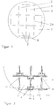
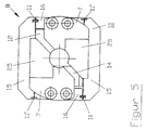
- the structure of the gap adjusting device 8 can be seen from FIG. 4 and FIG. 5.
- the valve is fastened to threaded bores 20 of a fastening plate 12.
- the solid body spring parallelogram 10, consisting of two first legs 15 and two second legs 16, is fastened to this fastening plate 12 by two joints 13. These joints 13 have an offset V which, with the length a, determines the transmission ratio of the piezo actuator length change to a change in the width of the gap w.
- the corner points of the solid-state spring joint parallelogram 10 form spring joints 11 and 11 '.
- the spring joints 11 and 11 ' are shifted from each other by the same offset V.
- the parallelogram is actuated by a piezoelectric actuator 14.
- This piezo actuator 14 is in turn fastened with its end faces to movable mounting plates 17.
- the movable receiving plates 17 are connected via joints 18 to the first legs 15 of the solid-state spring parallelogram 10.
- the piezo actuator 14 If the piezo actuator 14 is actuated with an electrical voltage, it stretches in length and this causes a rotation of the solid-state spring parallelogram 10 about the joints 13 and thus an enlargement of the main diagonals between the spring joints 11 'of the main diagonals and a shortening of the secondary diagonals the spring joints 11 of the secondary diagonals.
- the stroke of the piezo actuator 14 is increased by the multiplication factor ü.
- the cutter carriers 7 are fastened to the legs 16 by screws.
- the webs 6 have held the split edges 4 and 5 together until this time. This measure made simple manipulation and assembly of the splitting blades possible. In the de-energized state, the splitting blades go into their "zero" position.
- the gap adjusting device 8 If the gap adjusting device 8 is rotated in such a way that the underside becomes the upper side, then the assembled cutting edge carriers 7 and thus the gap cutting edges 4 and 5 are moved towards one another. This makes it possible to realize an actively closed gap 24 and an actively open gap 24 with the same gap adjusting device 8.
- the size of the control voltage of the piezo actuator 14 determines the opening width w of the gap.
- the stroke of the gap adjusting device 8 and thus the present gap width is constant over a long period of time, is reproducible or can be set with the dynamics of the change in the gap width over time.
- the piezoelectric actuator 14 has a hysteresis-shaped characteristic curve, but a linear relationship between the control and controlled variable is often desired in automated systems, it is advantageous to install a position measuring system in the gap adjusting device 8 as an actual value transmitter.
- a position measuring system in the gap adjusting device 8 as an actual value transmitter. This can e.g. a capacitive or inductive or an optical measuring system. If this is fastened to the splitting knife carriers 7 and the change in path of the splitting knife carriers 7 with respect to the fastening plate 12 is measured at this point, all drifts, instabilities and non-linearities that occur in the system can be minimized by an electronic control circuit.
- variable pinholes are produced entirely in the same way as the technology described for the variable gap.
- variable pinholes 30 The combination of two fixed pinholes 28 of suitable size and corresponding gap adjusting device 8 produces variable pinholes 30.
- Pinhole pairs consisting of a first chip 26 and a second chip 27, which are connected to one another by webs 6, are produced from the wafer 3.
- Each chip 26, 27 preferably has an octagonal border with the same side lengths and the same included angles.
- the pinhole 28 formed from mutually angled cutting edges 22.
- the angled cutting edges 22 form a polygon, preferably determined by the crystal lattice, a rectangle.
- the edge lengths d, e of the preferably square pinholes 28 are selected to be different in size depending on the application and can also be used with a pair of pinholes be of different sizes.
- the centers of the adjustment openings 29 and the center of the pinhole 28 lie on a line at a distance r from one another, the line running parallel to cutting edges 22.
- the second chip 27 there are the centrally arranged pinhole 28 with the edge length e and four adjustment openings 29, two of which are arranged with the edge lengths c as in the first chip 26 and the two other adjustment openings 29 while maintaining the distance r and the orientation of their Edges with edge lengths f lie parallel to cutting edges 22 on the extension of the pinhole diagonals (FIG. 6).
- the chips 26, 27 are assembled in accordance with FIG. 8 such that the first chip 26 with the smaller pinhole opening, i.e. with the cutting side, is glued upwards onto a splitting cutter support 7, with the adjustment openings being aligned with respect to the direction of movement 19.
- the second chip 27 is glued to the other splitting cutter carrier 7 in such a way that the centers of the pinholes 28 lie one above the other on a line and the adjustment openings 29 of both chips 26, 27 come to coincide.
- the adjustment openings lying on the diagonal are used for triangular variable pinholes 30 or the other adjustment openings 29 for rectangular variable pinholes 30.
- the cutting edge carriers 7 are ground in such a way that the mounting surface 25 lies in two parallel planes with a height offset which corresponds to the wafer thickness.
- the first chip 26 is placed on the lower mounting surface 25.
- a pinhole arrangement can also be realized in that a plurality of similar gap actuating devices 8 with mounted cutting edges 4, 5 (with straight cutting edges 22) are stacked one on top of the other. The respective directions of movement 19 are rotated about the stack axis.
- variable rectangular pinhole A variable polygon or an iris diaphragm is created by means of a plurality of gaps 24 which are rotated one above the other. It is advantageous to image the cutting edges 22 of the various gap adjusting devices 8 on one another.
- the piezo actuator 14 with the offset V is installed obliquely in the solid-state spring joint parallelogram 10
- the same conditions for the transmission ratio and the movement of the cutting edges 4, 5 on the cutting edge carriers 7 result in the case of the oblique solid-body spring parallelogram 10 with spring joint points 11, 11 ′ and joint points 13 offset by the amount V.
Landscapes
- Physics & Mathematics (AREA)
- Spectroscopy & Molecular Physics (AREA)
- General Physics & Mathematics (AREA)
- Engineering & Computer Science (AREA)
- General Engineering & Computer Science (AREA)
- High Energy & Nuclear Physics (AREA)
- Chemical & Material Sciences (AREA)
- Analytical Chemistry (AREA)
- Optics & Photonics (AREA)
- Micromachines (AREA)
Applications Claiming Priority (2)
| Application Number | Priority Date | Filing Date | Title |
|---|---|---|---|
| DE19924212077 DE4212077A1 (de) | 1992-04-10 | 1992-04-10 | Piezoelektrisch verstellbares Ventil und Verfahren zu ihrer Herstellung |
| DE4212077 | 1992-04-10 |
Publications (2)
| Publication Number | Publication Date |
|---|---|
| EP0565069A1 EP0565069A1 (de) | 1993-10-13 |
| EP0565069B1 true EP0565069B1 (de) | 1996-06-26 |
Family
ID=6456545
Family Applications (1)
| Application Number | Title | Priority Date | Filing Date |
|---|---|---|---|
| EP19930105722 Expired - Lifetime EP0565069B1 (de) | 1992-04-10 | 1993-04-07 | Verstellbare Blende und Verfahren zu ihrer Herstellung |
Country Status (2)
| Country | Link |
|---|---|
| EP (1) | EP0565069B1 (https=) |
| DE (2) | DE4212077A1 (https=) |
Families Citing this family (15)
| Publication number | Priority date | Publication date | Assignee | Title |
|---|---|---|---|---|
| ES2091521T3 (es) * | 1993-06-09 | 1996-11-01 | Hewlett Packard Gmbh | Componente optico ajustable. |
| DE19902624A1 (de) * | 1998-01-29 | 1999-09-30 | Leica Microsystems | Optische Anordnung zum spektralen Auffächern eines Lichtstrahls |
| DE19815080C1 (de) * | 1998-04-06 | 1999-09-09 | Inst Physikalische Hochtech Ev | Anordnung zur Erhöhung der spektralen Ortsauflösung eines Spektrometers |
| AU4668901A (en) * | 2000-04-05 | 2001-10-15 | Nortel Networks Limited | Variable optical attenuator |
| GB0110218D0 (en) * | 2001-04-26 | 2001-06-20 | Renishaw Plc | Optical slit |
| DE10244850A1 (de) | 2002-09-24 | 2004-04-01 | Carl Zeiss Jena Gmbh | Einstellbares Pinhole |
| DE10323922A1 (de) | 2003-05-22 | 2004-12-16 | Carl Zeiss Jena Gmbh | Einstellbares Pinhole |
| DE10323923A1 (de) * | 2003-05-22 | 2004-12-16 | Carl Zeiss Jena Gmbh | Einstellbares Pinhole, insbesondere für ein Laser-Scanning-Mikroskop |
| DE10345782A1 (de) * | 2003-10-01 | 2005-04-21 | Zeiss Carl Sms Gmbh | Variabler Abschwächer |
| DE102004005390A1 (de) * | 2004-02-04 | 2005-08-25 | Carl Zeiss Jena Gmbh | Verstellbare optische Spaltblende |
| DE102005028208A1 (de) | 2005-06-17 | 2006-12-28 | Siemens Ag | Strahlenblende für eine Röntgeneinrichtung |
| EP1916694A1 (en) * | 2006-10-25 | 2008-04-30 | ICT, Integrated Circuit Testing Gesellschaft für Halbleiterprüftechnik Mbh | Adjustable aperture element for particle beam device, method of operating and manufacturing thereof |
| FR2959344B1 (fr) * | 2010-04-26 | 2013-03-22 | Commissariat Energie Atomique | Dispositif optique pour analyser un echantillon par diffusion d'un faisceau de rayon x, dispositif de collimation et collimateur associes |
| DE102012208710B3 (de) * | 2012-05-24 | 2013-09-19 | Incoatec Gmbh | Verfahren zur Herstellung einer einkristallinen Röntgenblende und Röntgenanalysegerät mit einkristalliner Röntgenblende |
| CN104964743B (zh) * | 2015-06-08 | 2017-06-23 | 浙江海洋学院 | 小型棱镜摄谱仪的新型入射狭缝装置 |
Family Cites Families (8)
| Publication number | Priority date | Publication date | Assignee | Title |
|---|---|---|---|---|
| US2964998A (en) * | 1958-10-03 | 1960-12-20 | Fred J Middlestadt | Precision light aperture arrangement |
| FR2022123A1 (https=) * | 1968-08-14 | 1970-07-31 | Wollnik Hermann | |
| US4318023A (en) * | 1980-02-21 | 1982-03-02 | Physics International Company | Sagittally amplified piezoelectric actuator |
| EP0276337B1 (de) * | 1987-01-24 | 1989-11-29 | Dr.-Ing. Rudolf Hell GmbH | Blendenanordnung zur optoelektronischen Abtastung von Vorlagen |
| NL8700496A (nl) * | 1987-02-27 | 1988-09-16 | Stichting Tech Wetenschapp | Continu variabel microdiafragma. |
| EP0344515A3 (de) * | 1988-05-31 | 1991-01-30 | Siemens Aktiengesellschaft | Verfahren zur Herstellung einer Strahlformblende für ein Lithographiegerät |
| DE3914031C2 (de) * | 1989-04-28 | 1993-10-28 | Deutsche Aerospace | Mikromechanischer Aktuator |
| DE4110839A1 (de) * | 1991-04-04 | 1992-10-08 | Zeiss Carl Fa | Praezisionsspalt einstellbarer breite |
-
1992
- 1992-04-10 DE DE19924212077 patent/DE4212077A1/de active Granted
-
1993
- 1993-04-07 DE DE59303050T patent/DE59303050D1/de not_active Expired - Lifetime
- 1993-04-07 EP EP19930105722 patent/EP0565069B1/de not_active Expired - Lifetime
Also Published As
| Publication number | Publication date |
|---|---|
| DE4212077A1 (de) | 1993-10-14 |
| DE4212077C2 (https=) | 1994-01-27 |
| EP0565069A1 (de) | 1993-10-13 |
| DE59303050D1 (de) | 1996-08-01 |
Similar Documents
| Publication | Publication Date | Title |
|---|---|---|
| EP0565069B1 (de) | Verstellbare Blende und Verfahren zu ihrer Herstellung | |
| EP0799502B1 (de) | Piezoaktuatorisches antriebs- bzw. verstellelement | |
| DE19940124C2 (de) | Plattform mit einem Verschiebungsverstärkungsmechanismus | |
| DE60317156T2 (de) | Aktuator und dessen Herstellungsverfahren | |
| DE602004008534T2 (de) | Mikropositioniervorrichtung sowie Verfahren zur Kompensation von Position/Orientierung eines Werkzeuges | |
| EP0275338B1 (de) | Biegefedergelenk und Verfahren zu seiner Herstellung | |
| WO2008022797A1 (de) | Projektionsbelichtungsanlage und optisches system | |
| DE3932449A1 (de) | Antriebsmechanismus | |
| EP1035426A2 (de) | Vorrichtung zum Verschieben eines optischen Elementes entlang der optischen Achse | |
| WO2002093257A2 (de) | Projektionsbelichtungsanlage der mikrolithographie, | |
| EP1472562A1 (de) | Facettenspiegel mit mehreren spiegelfacetten | |
| EP0539889A2 (de) | Mikromechanischer Aktor | |
| DE10205425A1 (de) | Facettenspiegel mit mehreren Spiegelfacetten | |
| DE4338433C2 (de) | Mikro-Betätigungsglied und Verfahren zu dessen Herstellung | |
| DE102007030579B4 (de) | Lateral verstellbare Fassung für optische Elemente | |
| EP0134268B1 (de) | Justier- oder Positioniertisch und Verfahren zu dessen Herstellung | |
| EP1050070B1 (de) | Belichtungsanlage mit halteeinrichtung für ein substrat | |
| DE4224599A1 (de) | Elektrostatische Ablenkeinheit | |
| DE10237881B4 (de) | Mikromanipulator | |
| WO2002093228A2 (de) | Positioniereinrichtung | |
| WO2009127275A2 (de) | Elektrodenkamm, mikromechanisches bauteil und herstellungsverfahren für einen elektrodenkamm und für ein mikromechanisches bauteil | |
| DE69126738T2 (de) | Verfahren und Vorrichtung zur Herstellung einer Röntgenmaske | |
| WO2008009276A1 (de) | Lateral verstellbare fassung für optische elemente | |
| DE102018103053B3 (de) | Bauraumoptimierte Linsenfassung mit elastischen Verbindungsstrukturen | |
| DE102019202658B3 (de) | Mikromechanische Struktur und Verfahren zum Bereitstellen derselben |
Legal Events
| Date | Code | Title | Description |
|---|---|---|---|
| PUAI | Public reference made under article 153(3) epc to a published international application that has entered the european phase |
Free format text: ORIGINAL CODE: 0009012 |
|
| 17P | Request for examination filed |
Effective date: 19930407 |
|
| AK | Designated contracting states |
Kind code of ref document: A1 Designated state(s): DE FR GB IT NL |
|
| 17Q | First examination report despatched |
Effective date: 19950619 |
|
| GRAA | (expected) grant |
Free format text: ORIGINAL CODE: 0009210 |
|
| AK | Designated contracting states |
Kind code of ref document: B1 Designated state(s): DE FR GB IT NL |
|
| PG25 | Lapsed in a contracting state [announced via postgrant information from national office to epo] |
Ref country code: NL Free format text: LAPSE BECAUSE OF FAILURE TO SUBMIT A TRANSLATION OF THE DESCRIPTION OR TO PAY THE FEE WITHIN THE PRESCRIBED TIME-LIMIT Effective date: 19960626 Ref country code: IT Free format text: LAPSE BECAUSE OF FAILURE TO SUBMIT A TRANSLATION OF THE DESCRIPTION OR TO PAY THE FEE WITHIN THE PRE;WARNING: LAPSES OF ITALIAN PATENTS WITH EFFECTIVE DATE BEFORE 2007 MAY HAVE OCCURRED AT ANY TIME BEFORE 2007. THE CORRECT EFFECTIVE DATE MAY BE DIFFERENT FROM THE ONE RECORDED.SCRIBED TIME-LIMIT Effective date: 19960626 |
|
| REF | Corresponds to: |
Ref document number: 59303050 Country of ref document: DE Date of ref document: 19960801 |
|
| GBT | Gb: translation of ep patent filed (gb section 77(6)(a)/1977) |
Effective date: 19960903 |
|
| ET | Fr: translation filed | ||
| NLV1 | Nl: lapsed or annulled due to failure to fulfill the requirements of art. 29p and 29m of the patents act | ||
| PLBE | No opposition filed within time limit |
Free format text: ORIGINAL CODE: 0009261 |
|
| 26N | No opposition filed | ||
| REG | Reference to a national code |
Ref country code: GB Ref legal event code: IF02 |
|
| PGFP | Annual fee paid to national office [announced via postgrant information from national office to epo] |
Ref country code: DE Payment date: 20120620 Year of fee payment: 20 |
|
| PGFP | Annual fee paid to national office [announced via postgrant information from national office to epo] |
Ref country code: FR Payment date: 20120511 Year of fee payment: 20 Ref country code: GB Payment date: 20120423 Year of fee payment: 20 |
|
| REG | Reference to a national code |
Ref country code: DE Ref legal event code: R071 Ref document number: 59303050 Country of ref document: DE |
|
| REG | Reference to a national code |
Ref country code: GB Ref legal event code: PE20 Expiry date: 20130406 |
|
| PG25 | Lapsed in a contracting state [announced via postgrant information from national office to epo] |
Ref country code: DE Free format text: LAPSE BECAUSE OF EXPIRATION OF PROTECTION Effective date: 20130409 Ref country code: GB Free format text: LAPSE BECAUSE OF EXPIRATION OF PROTECTION Effective date: 20130406 |