EP0565069B1 - Adjustable diaphragm and manufacturing process - Google Patents
Adjustable diaphragm and manufacturing process Download PDFInfo
- Publication number
- EP0565069B1 EP0565069B1 EP19930105722 EP93105722A EP0565069B1 EP 0565069 B1 EP0565069 B1 EP 0565069B1 EP 19930105722 EP19930105722 EP 19930105722 EP 93105722 A EP93105722 A EP 93105722A EP 0565069 B1 EP0565069 B1 EP 0565069B1
- Authority
- EP
- European Patent Office
- Prior art keywords
- legs
- slit
- jaws
- slit jaws
- adjustable diaphragm
- Prior art date
- Legal status (The legal status is an assumption and is not a legal conclusion. Google has not performed a legal analysis and makes no representation as to the accuracy of the status listed.)
- Expired - Lifetime
Links
- 238000004519 manufacturing process Methods 0.000 title description 7
- 238000000034 method Methods 0.000 claims description 22
- 238000005530 etching Methods 0.000 claims description 11
- 239000007787 solid Substances 0.000 claims description 11
- 239000000463 material Substances 0.000 claims description 10
- 239000013078 crystal Substances 0.000 claims description 9
- 230000003993 interaction Effects 0.000 claims description 5
- 229910021421 monocrystalline silicon Inorganic materials 0.000 claims description 4
- 238000005524 ceramic coating Methods 0.000 claims description 2
- 239000011248 coating agent Substances 0.000 claims description 2
- 238000000576 coating method Methods 0.000 claims description 2
- 239000004020 conductor Substances 0.000 claims description 2
- 238000001312 dry etching Methods 0.000 claims description 2
- 238000000227 grinding Methods 0.000 claims description 2
- 239000002184 metal Substances 0.000 claims description 2
- 229910001220 stainless steel Inorganic materials 0.000 claims description 2
- 239000010935 stainless steel Substances 0.000 claims description 2
- 238000006073 displacement reaction Methods 0.000 claims 1
- 238000011156 evaluation Methods 0.000 claims 1
- 238000003754 machining Methods 0.000 claims 1
- 229920002120 photoresistant polymer Polymers 0.000 claims 1
- 239000011347 resin Substances 0.000 claims 1
- 229920005989 resin Polymers 0.000 claims 1
- 238000001039 wet etching Methods 0.000 claims 1
- 238000005520 cutting process Methods 0.000 description 39
- 239000000969 carrier Substances 0.000 description 10
- 230000005540 biological transmission Effects 0.000 description 4
- 230000001965 increasing effect Effects 0.000 description 4
- 101100269850 Caenorhabditis elegans mask-1 gene Proteins 0.000 description 3
- XUIMIQQOPSSXEZ-UHFFFAOYSA-N Silicon Chemical compound [Si] XUIMIQQOPSSXEZ-UHFFFAOYSA-N 0.000 description 2
- 238000004026 adhesive bonding Methods 0.000 description 2
- 239000003637 basic solution Substances 0.000 description 2
- 229910052710 silicon Inorganic materials 0.000 description 2
- 239000010703 silicon Substances 0.000 description 2
- 239000000243 solution Substances 0.000 description 2
- 239000002178 crystalline material Substances 0.000 description 1
- 238000013016 damping Methods 0.000 description 1
- 238000009760 electrical discharge machining Methods 0.000 description 1
- 230000005670 electromagnetic radiation Effects 0.000 description 1
- 238000005516 engineering process Methods 0.000 description 1
- 230000001939 inductive effect Effects 0.000 description 1
- 150000004767 nitrides Chemical class 0.000 description 1
- 230000003287 optical effect Effects 0.000 description 1
- 238000000206 photolithography Methods 0.000 description 1
- 239000004033 plastic Substances 0.000 description 1
- 230000001105 regulatory effect Effects 0.000 description 1
- 238000004904 shortening Methods 0.000 description 1
- 239000007858 starting material Substances 0.000 description 1
- 238000003860 storage Methods 0.000 description 1
- 239000000126 substance Substances 0.000 description 1
- 238000003466 welding Methods 0.000 description 1
Images


Classifications
-
- H—ELECTRICITY
- H01—ELECTRIC ELEMENTS
- H01J—ELECTRIC DISCHARGE TUBES OR DISCHARGE LAMPS
- H01J37/00—Discharge tubes with provision for introducing objects or material to be exposed to the discharge, e.g. for the purpose of examination or processing thereof
- H01J37/02—Details
- H01J37/04—Arrangements of electrodes and associated parts for generating or controlling the discharge, e.g. electron-optical arrangement, ion-optical arrangement
- H01J37/09—Diaphragms; Shields associated with electron or ion-optical arrangements; Compensation of disturbing fields
-
- G—PHYSICS
- G01—MEASURING; TESTING
- G01J—MEASUREMENT OF INTENSITY, VELOCITY, SPECTRAL CONTENT, POLARISATION, PHASE OR PULSE CHARACTERISTICS OF INFRARED, VISIBLE OR ULTRAVIOLET LIGHT; COLORIMETRY; RADIATION PYROMETRY
- G01J3/00—Spectrometry; Spectrophotometry; Monochromators; Measuring colours
- G01J3/02—Details
- G01J3/04—Slit arrangements slit adjustment
-
- G—PHYSICS
- G02—OPTICS
- G02B—OPTICAL ELEMENTS, SYSTEMS OR APPARATUS
- G02B5/00—Optical elements other than lenses
- G02B5/005—Diaphragms
-
- G—PHYSICS
- G21—NUCLEAR PHYSICS; NUCLEAR ENGINEERING
- G21K—TECHNIQUES FOR HANDLING PARTICLES OR IONISING RADIATION NOT OTHERWISE PROVIDED FOR; IRRADIATION DEVICES; GAMMA RAY OR X-RAY MICROSCOPES
- G21K1/00—Arrangements for handling particles or ionising radiation, e.g. focusing or moderating
- G21K1/02—Arrangements for handling particles or ionising radiation, e.g. focusing or moderating using diaphragms, collimators
- G21K1/04—Arrangements for handling particles or ionising radiation, e.g. focusing or moderating using diaphragms, collimators using variable diaphragms, shutters, choppers
Definitions
- the invention relates to an adjustable diaphragm according to the preamble of claims 1 and 2. It consists of two first legs rotatably mounted about their center and two second legs, which are movably connected to the first legs to form a parallelogram and each have a split edge of a pair of split blades wear, and from an actuator by means of which the shape of the parallelogram against the action of a restoring force and thus the distance between the splitting blades can be changed.
- the invention further relates to a method for producing such an aperture.
- the parallelogram is composed of individual parts to be manufactured, the precision that can be achieved, particularly with regard to the symmetry of the movement of the diaphragm plates or slitting blades, remains limited, because length differences must be expected both during manufacture and when assembling these parts, which is inevitable Leads to management errors.
- the splitting wedge angle is also relatively large with this screen, since the splitting blades are attached individually by welding.
- the invention is therefore based on the object of creating an adjustable diaphragm of the type mentioned which, on the one hand, is as straightforward as possible in terms of its structure, but on the other hand also permits highly precise adjustability, in particular symmetrical movement of the splitting blades.
- the basic solution should be equally suitable for variable gaps as well as for variable pinholes.
- the invention is also based on the object of specifying a method for producing such an aperture.
- the problem is to be solved that, in addition to ensuring precise adjustability, the splitting edges or pinholes can also be produced with the highest reproducible quality with regard to the geometric dimensions and the surface shape, in particular with an extremely low edge roughness of the cutting edges or pinholes.
- the previous complex manual production is to be replaced by a technologically controllable industrial and comparatively inexpensive process.
- a preferred embodiment of the invention consists in that the end faces of the piezo actuator rest on receiving plates, each of which is connected to one of the first legs via a joint. This compensates for the rotary movements associated with the changes in length of the piezo actuator, which are caused by the parallelogram movement.
- each of the split edges is provided with at least two cutting edges which are at an angle to one another.
- a preferred embodiment provides here that the cutting edges of each slitting blade form a rectangular opening.
- variable rectangular or specially square opening geometries of the pinholes can be realized. If one of the two split blades with a rectangular opening is arranged rotated by an angle on the second leg, a variable triangular pinhole can also be formed in the interaction of these split blades.
- split blades consist of a wet or dry etchable, single-crystalline material and have cutting edges running along a selected crystal lattice direction. This results in an extremely low roughness of the cutting edges.
- the split edges are preferably made from single-crystal silicon.
- the active surface of the split edges in particular the cutting edges of the split edges, can be provided with a metal, plastic or ceramic coating in order to optimally adapt the physical and chemical properties of the split edges to the medium to be regulated. For example, it is possible to avoid reflections of electromagnetic radiation or material fluorescence with a damping coating that is adapted to the wavelength used.
- Another preferred embodiment provides that for measuring the gap width Position measuring system is arranged.
- the voltage at the piezo actuator can be set according to a target gap width via a control loop. This enables a linearization of the adjustment movement. Changes in length due to temperature fluctuations in the environment can also be compensated for.
- a special embodiment is also that several pairs of split edges, each provided with a split control device, are stacked one above the other in planes parallel to one another in such a way that a desired opening geometry, e.g. an octagon arises.
- the method for producing a piezoelectrically adjustable diaphragm which consists of a gap actuating device with a piezo actuator and at least one pair of gap cutting edges, is characterized according to the invention in that at least two gap cutting edges which are connected to one another by webs are first produced, the contour of the gap cutting edges using microlitography in a resist mask located on a wafer is written and transferred into the wafer by means of at least one etching process, in addition that a solid-state spring joint parallelogram consisting of two first opposing legs and two second opposing legs is prefabricated, the first leg of which is produced by means of joints by means of four spring joints are rotatably mounted in a mounting plate, and that the piezo actuator is then arranged off-center between the first legs and that the gap cutting edges connected by webs then increase will soon be mounted as a one-piece pair of split blades on the second legs and that after the fixed connection between the pair of split blades and the gap actuating device has been made by first deflecting the piezo
- the position of the structure of a useful structure mask for crystal orientation of the material of the wafer is advantageously determined by first performing a trial etching with the aid of alignment marks, assessing the result according to symmetry features and then aligning the position of the useful structure mask to a selected crystal lattice direction of the wafer. This results in accuracies of less than 0.002 ° deviation reached.
- the useful structure mask is preferably aligned with the wafer in such a way that a crystal lattice direction of the material, which is the trace of a [111] surface cutting the wafer surface, largely corresponds to the direction of a cutting edge of the slitting edge.
- the solid-state spring parallelogram is produced from one piece of a solid, electrically conductive material by means of electrical discharge machining. This ensures high contour precision and thin, easily reproducible material thicknesses, particularly at the spring joints.
- the solid-state spring parallelogram is preferably made of stainless steel.
- prefabricated splitting knife carriers provided with mounting surfaces for the splitting blades are first attached, then plane parallelism of the mounting surfaces is produced by at least one grinding process and only then the splitting blades on the mounting surfaces to be assembled.
- the splitting blades are preferably attached by gluing.
- the solution according to the invention provides a remedy here.
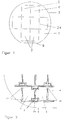
- FIG. 1 shows a wafer 3 with a microlithographically generated useful structure mask 1. On it, four pairs of cutting edges 2 can be seen, which are interconnected by bridges 23. The splitting blades 4 and 5 of a pair of splitting blades 2 are connected to one another by webs 6 (FIG. 2).
- a special alignment mark field with etching structures is generated on the coated wafer surface by photolithography.
- the alignment mark field is pre-oriented after the main wafer phase 9 (primary flat).
- the resist mask is removed using the usual methods and the wafer 3 in basic solution, for example. 30% KOH, etched. Typical undercuts of the etching structures are formed, which are examined for symmetry features with the aid of a measuring microscope. The necessary adjustment of the useful structure mask 1 to the crystal orientation of the wafer 3 is determined.
- the wafer 3 is coated with a resist a second time.
- the useful structure mask 1 is transferred to the coated silicon wafer 3 by exposure.
- the structure is transferred to the wafer 3 in a manner analogous to the etching of the alignment marks.
- the etching process simultaneously produces the cutting edge geometry acting as a gap in an almost ideal manner and the contour of the cutting edge in one work step.
- the pairs of cutting edges 2 are produced which match each other in high quality.
- the etching process is stopped when the bottom of the gap 24 of the pair of cutting edges 2 is about 100 ⁇ m wide.
- the pair of split edges 2 is mounted on the gap adjusting device 8.
- the assembly of the pair of split blades 2 is carried out on specially manufactured split blade carriers 7 which, after being mounted on legs 16 of the gap adjusting device 8, have been ground together together (FIG. 3).
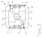
- the structure of the gap adjusting device 8 can be seen from FIG. 4 and FIG. 5.
- the valve is fastened to threaded bores 20 of a fastening plate 12.
- the solid body spring parallelogram 10, consisting of two first legs 15 and two second legs 16, is fastened to this fastening plate 12 by two joints 13. These joints 13 have an offset V which, with the length a, determines the transmission ratio of the piezo actuator length change to a change in the width of the gap w.
- the corner points of the solid-state spring joint parallelogram 10 form spring joints 11 and 11 '.
- the spring joints 11 and 11 ' are shifted from each other by the same offset V.
- the parallelogram is actuated by a piezoelectric actuator 14.
- This piezo actuator 14 is in turn fastened with its end faces to movable mounting plates 17.
- the movable receiving plates 17 are connected via joints 18 to the first legs 15 of the solid-state spring parallelogram 10.
- the piezo actuator 14 If the piezo actuator 14 is actuated with an electrical voltage, it stretches in length and this causes a rotation of the solid-state spring parallelogram 10 about the joints 13 and thus an enlargement of the main diagonals between the spring joints 11 'of the main diagonals and a shortening of the secondary diagonals the spring joints 11 of the secondary diagonals.
- the stroke of the piezo actuator 14 is increased by the multiplication factor ü.
- the cutter carriers 7 are fastened to the legs 16 by screws.
- the webs 6 have held the split edges 4 and 5 together until this time. This measure made simple manipulation and assembly of the splitting blades possible. In the de-energized state, the splitting blades go into their "zero" position.
- the gap adjusting device 8 If the gap adjusting device 8 is rotated in such a way that the underside becomes the upper side, then the assembled cutting edge carriers 7 and thus the gap cutting edges 4 and 5 are moved towards one another. This makes it possible to realize an actively closed gap 24 and an actively open gap 24 with the same gap adjusting device 8.
- the size of the control voltage of the piezo actuator 14 determines the opening width w of the gap.
- the stroke of the gap adjusting device 8 and thus the present gap width is constant over a long period of time, is reproducible or can be set with the dynamics of the change in the gap width over time.
- the piezoelectric actuator 14 has a hysteresis-shaped characteristic curve, but a linear relationship between the control and controlled variable is often desired in automated systems, it is advantageous to install a position measuring system in the gap adjusting device 8 as an actual value transmitter.
- a position measuring system in the gap adjusting device 8 as an actual value transmitter. This can e.g. a capacitive or inductive or an optical measuring system. If this is fastened to the splitting knife carriers 7 and the change in path of the splitting knife carriers 7 with respect to the fastening plate 12 is measured at this point, all drifts, instabilities and non-linearities that occur in the system can be minimized by an electronic control circuit.
- variable pinholes are produced entirely in the same way as the technology described for the variable gap.
- variable pinholes 30 The combination of two fixed pinholes 28 of suitable size and corresponding gap adjusting device 8 produces variable pinholes 30.
- Pinhole pairs consisting of a first chip 26 and a second chip 27, which are connected to one another by webs 6, are produced from the wafer 3.
- Each chip 26, 27 preferably has an octagonal border with the same side lengths and the same included angles.
- the pinhole 28 formed from mutually angled cutting edges 22.
- the angled cutting edges 22 form a polygon, preferably determined by the crystal lattice, a rectangle.
- the edge lengths d, e of the preferably square pinholes 28 are selected to be different in size depending on the application and can also be used with a pair of pinholes be of different sizes.
- the centers of the adjustment openings 29 and the center of the pinhole 28 lie on a line at a distance r from one another, the line running parallel to cutting edges 22.
- the second chip 27 there are the centrally arranged pinhole 28 with the edge length e and four adjustment openings 29, two of which are arranged with the edge lengths c as in the first chip 26 and the two other adjustment openings 29 while maintaining the distance r and the orientation of their Edges with edge lengths f lie parallel to cutting edges 22 on the extension of the pinhole diagonals (FIG. 6).
- the chips 26, 27 are assembled in accordance with FIG. 8 such that the first chip 26 with the smaller pinhole opening, i.e. with the cutting side, is glued upwards onto a splitting cutter support 7, with the adjustment openings being aligned with respect to the direction of movement 19.
- the second chip 27 is glued to the other splitting cutter carrier 7 in such a way that the centers of the pinholes 28 lie one above the other on a line and the adjustment openings 29 of both chips 26, 27 come to coincide.
- the adjustment openings lying on the diagonal are used for triangular variable pinholes 30 or the other adjustment openings 29 for rectangular variable pinholes 30.
- the cutting edge carriers 7 are ground in such a way that the mounting surface 25 lies in two parallel planes with a height offset which corresponds to the wafer thickness.
- the first chip 26 is placed on the lower mounting surface 25.
- a pinhole arrangement can also be realized in that a plurality of similar gap actuating devices 8 with mounted cutting edges 4, 5 (with straight cutting edges 22) are stacked one on top of the other. The respective directions of movement 19 are rotated about the stack axis.
- variable rectangular pinhole A variable polygon or an iris diaphragm is created by means of a plurality of gaps 24 which are rotated one above the other. It is advantageous to image the cutting edges 22 of the various gap adjusting devices 8 on one another.
- the piezo actuator 14 with the offset V is installed obliquely in the solid-state spring joint parallelogram 10
- the same conditions for the transmission ratio and the movement of the cutting edges 4, 5 on the cutting edge carriers 7 result in the case of the oblique solid-body spring parallelogram 10 with spring joint points 11, 11 ′ and joint points 13 offset by the amount V.
Landscapes
- Physics & Mathematics (AREA)
- Spectroscopy & Molecular Physics (AREA)
- General Physics & Mathematics (AREA)
- Engineering & Computer Science (AREA)
- General Engineering & Computer Science (AREA)
- High Energy & Nuclear Physics (AREA)
- Chemical & Material Sciences (AREA)
- Analytical Chemistry (AREA)
- Optics & Photonics (AREA)
- Micromachines (AREA)
Description
Die Erfindung betrifft eine verstellbare Blende nach dem Oberbegriff der Ansprüche 1 und 2. Sie besteht aus zwei um ihre Mitte drehbar gelagerten ersten Schenkeln sowie zwei zweiten Schenkeln, die mit den ersten Schenkeln unter Bildung eines Parallelogramms bewegbar verbunden sind und die jeweils eine Spaltschneide eines Spaltschneidenpaares tragen, sowie aus einer Betätigungseinrichtung mittels der die Form des Parallelogramms gegen die Wirkung einer Rückstellkraft und damit der Abstand der Spaltschneiden veränderbar ist.The invention relates to an adjustable diaphragm according to the preamble of
Die Erfindung bezieht sich ferner auf ein Verfahren zur Herstellung einer solchen Blende.The invention further relates to a method for producing such an aperture.
Eine verstellbare Blende der eingangs genannten Art, bei der zwei Blendenplatten bzw. Spaltschneiden über eine Parallelogrammführung bewegt werden, ist aus der US-PS 2,964,998 bekannt. Bei dieser Blende sind jeweils die benachbarten Schenkel mit Hilfe von Drehzapfen bewegbar verbunden. Auch die mittige Lagerung der ersten beiden Schenkel am mit einem Fenster versehenen Gehäuse erfolgt mittels Drehzapfen. Als Betätigungseinrichtung dient eine von Hand verstellbare, auf das eine Ende einer der die Spaltschneiden tragenden Schenkel wirkende Mikrometerschraube. Die Rückstellkraft wird von einer auf das andere Ende dieses Schenkels wirkenden Feder aufgebracht.An adjustable diaphragm of the type mentioned in the introduction, in which two diaphragm plates or slitting blades are moved via a parallelogram guide, is known from US Pat. No. 2,964,998. In this diaphragm, the adjacent legs are movably connected with the help of pivots. The central mounting of the first two legs on the housing provided with a window also takes place by means of pivot pins. A manually adjustable micrometer screw acting on the one end of one of the legs carrying the split blades serves as the actuating device. The restoring force is applied by a spring acting on the other end of this leg.
Da das Parallelogramm aus einzelnen zu fertigenden Teilen zusammengesetzt ist, bleibt die erreichbare Präzision, insbesondere was die Symmetrie der Bewegung der Blendenplatten bzw. Spaltschneiden anbelangt, begrenzt, denn sowohl bei der Fertigung als auch beim Zusammensetzen dieser Teile muß mit Längendifferenzen gerechnet werden, was zwangsläufig Führungsfehler zur Folge hat. Auch der Spaltkeilwinkel ist bei dieser Blende verhältnismäßig groß, da die Spaltschneiden einzeln durch Schweißen befestigt werden.Since the parallelogram is composed of individual parts to be manufactured, the precision that can be achieved, particularly with regard to the symmetry of the movement of the diaphragm plates or slitting blades, remains limited, because length differences must be expected both during manufacture and when assembling these parts, which is inevitable Leads to management errors. The splitting wedge angle is also relatively large with this screen, since the splitting blades are attached individually by welding.
Der Erfindung liegt daher die Aufgabe zugrunde, eine verstellbare Blende der eingangs genannten Art zu schaffen, die einerseits in ihrem Aufbau möglichst unkompliziert ist, andererseits aber auch eine hochpräzise Verstellbarkeit, insbesondere symmetrische Bewegung der Spaltschneiden zuläßt.The invention is therefore based on the object of creating an adjustable diaphragm of the type mentioned which, on the one hand, is as straightforward as possible in terms of its structure, but on the other hand also permits highly precise adjustability, in particular symmetrical movement of the splitting blades.
Die prinzipielle Lösung soll sowohl für variable Spalte als auch für variable Pinholes gleichermaßen geeignet sein.The basic solution should be equally suitable for variable gaps as well as for variable pinholes.
Der Erfindung liegt ferner die Aufgabe zugrunde, ein Verfahren zur Herstellung einer solchen Blende anzugeben. Für hochpräzise Anwendungen soll dabei das Problem gelöst werden, daß neben der Gewährleistung einer präzisen Verstellbarkeit auch die Spaltschneiden bzw. Pinholes mit höchster reproduzierbarer Güte bezüglich der geometrischen Abmessungen und der Oberflächengestalt, insbesondere mit einer extrem geringen Kantenrauhigkeit der Schneiden bzw. Pinholes hergestellt werden können. Dabei soll die bisherige aufwendige handwerkliche Fertigung durch einen technologisch beherrschbaren industriellen und vergleichsweise kostengünstigen Prozeß abgelöst werden.The invention is also based on the object of specifying a method for producing such an aperture. For high-precision applications, the problem is to be solved that, in addition to ensuring precise adjustability, the splitting edges or pinholes can also be produced with the highest reproducible quality with regard to the geometric dimensions and the surface shape, in particular with an extremely low edge roughness of the cutting edges or pinholes. The previous complex manual production is to be replaced by a technologically controllable industrial and comparatively inexpensive process.
Die Ansprüche 1 und 2 beschreiben erfindungsgemäße Lö sungen:
- Die vorgenannte Aufgabe wird erfindungsgemäß dadurch gelöst, daß die Betätigungseinrichtung aus einem Piezoaktuator besteht, der zwischen den ersten beiden Schenkeln seitlich beabstandet von den Lagerpunkten dieser Schenkel angeordnet ist, und daß benachbarte erste und zweite Schenkel über Festkörperfedergelenke miteinander verbunden sind, wobei sämtliche Gelenkpunkte des einen der ersten Schenkel gegenüber denjenigen des anderen ersten Schenkels quer zur Bewegungsrichtung des Piezoaktuators um einen Betrag V versetzt sind.
- Die Aufgabe wird ebenso erfindungsgemäß dadurch gelöst, daß die Betätigungseinrichtung aus einem Piezoaktuator besteht, der zwischen den ersten beiden Schenkeln schräg angeordnet ist, indem eine der beiden Endflächen des Piezoaktuators gegenüber der anderen Endfläche am jeweiligen Schenkel im Abstand von dessen Lagerpunkt um einen Betrag V versetzt angreift, und daß benachbarte erste und zweite Schenkel über Festkörperfedergelenke miteinander verbunden sind.
- The aforementioned object is achieved in that the actuating device consists of a piezo actuator, which is arranged between the first two legs laterally spaced from the bearing points of these legs, and that adjacent first and second legs are connected to one another via solid spring joints, all articulation points of one the first leg is offset by an amount V from that of the other first leg transversely to the direction of movement of the piezo actuator.
- The object is also achieved according to the invention in that the actuating device consists of a piezo actuator which is arranged obliquely between the first two legs by one of the two end faces of the piezo actuator being offset by an amount V from the respective leg at a distance from its bearing point attacks, and that adjacent first and second legs are connected to each other via solid spring joints.
Eine bevorzugte Ausführungsform der Erfindung besteht darin, daß der Piezoaktuator mit seinen Endflächen auf Aufnahmetellern aufliegt, welche jeweils über ein Gelenk mit einem der ersten Schenkel verbunden sind. Hierdurch werden die mit den Längenänderungen des Piezoaktuators einhergehenden Drehbewegungen ausgeglichen, die durch die Parallelogrammbewegung entstehen.A preferred embodiment of the invention consists in that the end faces of the piezo actuator rest on receiving plates, each of which is connected to one of the first legs via a joint. This compensates for the rotary movements associated with the changes in length of the piezo actuator, which are caused by the parallelogram movement.
Für Pinholeanwendungen ist es günstig, wenn jede der Spaltschneiden mit zumindest zwei im Winkel zueinander stehenden Schneidkanten versehen ist. Eine bevorzugte Ausbildungsform sieht hier vor, daß die Schneidkanten einer jeden Spaltschneide eine rechteckige Öffnung bilden. Im Zusammenwirken beider Spaltschneiden können somit variable rechteckige oder speziell quadratische Öffnungsgeometrien der Pinholes realisiert werden. Wenn eine der beiden eine rechteckige Öffnung aufweisenden Spaltschneiden um einen Winkel verdreht auf dem zweiten Schenke angeordnet ist, kann im Zusammenwirken dieser Spaltschneiden auch ein variables dreieckförmiges Pinhole gebildet werden.For pinhole applications, it is advantageous if each of the split edges is provided with at least two cutting edges which are at an angle to one another. A preferred embodiment provides here that the cutting edges of each slitting blade form a rectangular opening. In the interaction of both splitting edges, variable rectangular or specially square opening geometries of the pinholes can be realized. If one of the two split blades with a rectangular opening is arranged rotated by an angle on the second leg, a variable triangular pinhole can also be formed in the interaction of these split blades.
Eine besonders vorteilhafte Ausführungsform der Erfindung ist auch dadurch gegeben, daß die Spaltschneiden aus einem naß- oder trockenätzbaren, einkristallinen Material bestehen und entlang einer ausgewählten Kristallgitterrichtung verlaufende Schneidkanten aufweisen. Hierdurch wird eine extrem niedrige Rauhigkeit der Schneidkanten erreicht.A particularly advantageous embodiment of the invention is also given in that the split blades consist of a wet or dry etchable, single-crystalline material and have cutting edges running along a selected crystal lattice direction. This results in an extremely low roughness of the cutting edges.
Vorzugsweise sind die Spaltschneiden aus einkristallinem Silizium gefertigt.The split edges are preferably made from single-crystal silicon.
Die Wirkfläche der Spaltschneiden, insbesondere die Schneidkanten der Spaltschneiden, kann mit einem Metall-, Kunststoff- oder Keramiküberzug versehen sein, um die physikalischen und chemischen Eigenschaffen der Spaltschneiden optimal dem zu regulierenden Medium anzupassen. So ist es beispielsweise möglich, mit einer dämpfenden, der verwendeten Wellenlänge angepaßten Beschichtung Reflexionen elektromagnetischer Strahlung oder Materialfluoreszenz zu vermeiden.The active surface of the split edges, in particular the cutting edges of the split edges, can be provided with a metal, plastic or ceramic coating in order to optimally adapt the physical and chemical properties of the split edges to the medium to be regulated. For example, it is possible to avoid reflections of electromagnetic radiation or material fluorescence with a damping coating that is adapted to the wavelength used.
Eine andere vorzugsweise Ausführungsform sieht vor, daß zur Messung der Spaltweite ein Wegmeßsystem angeordnet ist. Mit Hilfe der gemessenen IST-Spaltweite kann über einen Regelkreis die Spannung am Piezoaktuator entsprechend einer Soll-Spaltweite eingestellt werden. Hierdurch wird eine Linearisierung der Verstellbewegung möglich. Auch Längenänderungen aufgrund von Temperaturschwankungen der Umgebung können so ausgeglichen werden.Another preferred embodiment provides that for measuring the gap width Position measuring system is arranged. With the help of the measured actual gap width, the voltage at the piezo actuator can be set according to a target gap width via a control loop. This enables a linearization of the adjustment movement. Changes in length due to temperature fluctuations in the environment can also be compensated for.
Eine besondere Ausbildungsform besteht auch darin, daß mehrere, jeweils mit einer Spaltstelleinrichtung versehene Spaltschneidenpaare in Ebenen parallel zueinander derart übereinander gestapelt sind, daß im Zusammenwirken der Spaltstelleinrichtungen eine gewünschte Öffnungsgeometrie, z.B. ein 8-Eck, entsteht.A special embodiment is also that several pairs of split edges, each provided with a split control device, are stacked one above the other in planes parallel to one another in such a way that a desired opening geometry, e.g. an octagon arises.
Das Verfahren zur Herstellung einer piezoelektrisch verstellbaren Blende, die aus einer Spalt-Stelleinrichtung mit einem Piezoaktuator und mindestens einem Spaltschneidenpaar besteht, zeichnet sich erfindungsgemäß dadurch aus, daß zunächst zumindest zwei durch Stege miteinander verbundene Spaltschneiden hergestellt werden, wobei die Kontur der Spaltschneiden mittels Mikrolitographie in eine sich auf einem Wafer befindende Resistmaske geschrieben und mittels mindestens eines Ätzprozesses in den Wafer übertragen wird, daß ferner ein aus zwei ersten gegenüberliegenden Schenkeln und zwei zweiten gegenüberliegenden Schenkeln bestehendes, durch vier Federgelenke miteinander verbundenes Festkörperfedergelenk-Parallelogramm vorgefertigt wird, dessen erste Schenkel mittels Gelenken in einer Befestigungsplatte drehbar gelagert sind, und daß sodann der Piezoaktuator außermittig zwischen den ersten Schenkeln angeordnet wird und daß danach die durch Stege verbundenen Spaltschneiden zunächst als einteiliges Spaltschneidenpaar auf den zweiten Schenkeln montiert werden und daß nach Herstellung der festen Verbindung zwischen Spaltschneidenpaar und Spalt-Stelleinrichtung durch erstmaliges Auslenken des Piezoaktuators das Spaltschneidenpaar durch Brechen der Stege in die Spaltschneiden vereinzelt wird. Vorzugsweise wird als Material für den Wafer einkristallines Silizium verwendet.The method for producing a piezoelectrically adjustable diaphragm, which consists of a gap actuating device with a piezo actuator and at least one pair of gap cutting edges, is characterized according to the invention in that at least two gap cutting edges which are connected to one another by webs are first produced, the contour of the gap cutting edges using microlitography in a resist mask located on a wafer is written and transferred into the wafer by means of at least one etching process, in addition that a solid-state spring joint parallelogram consisting of two first opposing legs and two second opposing legs is prefabricated, the first leg of which is produced by means of joints by means of four spring joints are rotatably mounted in a mounting plate, and that the piezo actuator is then arranged off-center between the first legs and that the gap cutting edges connected by webs then increase will soon be mounted as a one-piece pair of split blades on the second legs and that after the fixed connection between the pair of split blades and the gap actuating device has been made by first deflecting the piezo actuator, the pair of split blades will be separated into the split blades by breaking the webs. Monocrystalline silicon is preferably used as the material for the wafer.
Die Lage der Struktur einer Nutzstrukturmaske zur Kristallorientierung des Materials des Wafers wird in vorteilhafter Weise dadurch bestimmt, daß zunächst mit Hilfe von Justiermarken eine Probeätzung durchgeführt, das Ergebnis nach Symmetriemerkmalen beurteilt und danach die Lage der Nutzstrukturmaske zu einer ausgewählten Kristallgitterrichtung des Wafers ausgerichtet wird. Hierdurch werden Genauigkeiten von kleiner 0,002° Abweichung erreicht. Vorzugsweise wird die Nutzstrukturmaske zum Wafer dabei so ausgerichtet, daß eine Kristallgitterrichtung des Materials, welche die Spur einer die Waferoberfläche schneidende [111]-Fläche ist, mit der Richtung einer Schneidkante der Spaltschneide weitestgehend übereinstimmt.The position of the structure of a useful structure mask for crystal orientation of the material of the wafer is advantageously determined by first performing a trial etching with the aid of alignment marks, assessing the result according to symmetry features and then aligning the position of the useful structure mask to a selected crystal lattice direction of the wafer. This results in accuracies of less than 0.002 ° deviation reached. The useful structure mask is preferably aligned with the wafer in such a way that a crystal lattice direction of the material, which is the trace of a [111] surface cutting the wafer surface, largely corresponds to the direction of a cutting edge of the slitting edge.
Eine vorteilhafte Weiterbildung des ertindungsgemäßen Verfahrens besteht auch darin, daß das Festkörperfedergelenk-Parallelogramm aus einem Stück eines massiven, elektrisch leiffähigen Materials durch Elektroerosion gefertigt wird. Hierdurch werden eine hohe Präzision der Kontur und dünne gut reproduzierbare Materialstärken, insbesondere an den Federgelenken, gewährleistet. Vorzugsweise wird das Festkörperfedergelenk-Parallelogramm aus Edelstahl gefertigt.An advantageous further development of the method according to the invention also consists in the fact that the solid-state spring parallelogram is produced from one piece of a solid, electrically conductive material by means of electrical discharge machining. This ensures high contour precision and thin, easily reproducible material thicknesses, particularly at the spring joints. The solid-state spring parallelogram is preferably made of stainless steel.
Günstig zur Gewährleistung einer hohen Präzision ist es auch, wenn auf den zweiten Schenkeln des Festkörperfedergelenk-Parallelogramms zunächst vorgefertigte, mit Montageflächen für die Spaltschneiden versehene Spaltschneidenträger befestigt werden, anschließend Planparallelität der Montageflächen durch wenigstens einen Schleifvorgang hergestellt wird und erst danach die Spaltschneiden auf den Montageflächen montiert werden.To ensure high precision, it is also advantageous if, on the second legs of the solid-state spring joint parallelogram, prefabricated splitting knife carriers provided with mounting surfaces for the splitting blades are first attached, then plane parallelism of the mounting surfaces is produced by at least one grinding process and only then the splitting blades on the mounting surfaces to be assembled.
Vorzugsweise werden die Spaltschneiden durch Aufkleben befestigt.The splitting blades are preferably attached by gluing.
Mit dem erfindungsgemäßen Verfahren gelingt es, eine extrem genau verstellbare Blende mit einem sehr homogenen (Licht-) Spalt herzustellen. Technisch sicher beherrschbar sind Rauhigkeiten von 50 nm bei den Schneidenkanten und auf 10 mm Spaltlänge 200 nm Abweichung von der Parallelen.With the method according to the invention, it is possible to produce an extremely precisely adjustable diaphragm with a very homogeneous (light) gap. Roughness of 50 nm at the cutting edges and a deviation of 200 nm over 10 mm gap length are technically manageable.
Es ist zwar eine kontinuierlich einstellbare Mikroblende bekannt, deren Antrieb piezoelektrisch erfolgt (US-PS 4,880,294), zur Übertragung der Bewegung auf die Blendenplattenpaare bzw. Spaltschneiden dient hierbei jedoch ein im Vergleich zum Erfindungsgegenstand wesentlich komplizierteres, weil eine Vielzahl von Hebelarmen bzw. Schenkeln aufweisendes Hebelsystem. Anders als beim Erfindungsgegenstand hängt die Symmetrie der Bewegung hierbei im wesentlichen von der Position zweier Stellschrauben ab. Montage und insbesondere der Justieraufwand sind erheblich. Auch die Herstellung einer solchen Blende ist kompliziert. Zur Bildung eines Pinholes sind vier präzise gefertigte Teile erforderlich, die bei Befestigung auf den Schenkeln zueinander genau justiert werden müssen. Die Kantenrauhigkeiten liegen selbst bei geläppten Kanten bei ca. 1µm. Geringere Rauhigkeiten erfordern einen sehr großen technologischen Aufwand.Although a continuously adjustable micro-diaphragm is known, the drive of which is piezoelectric (US Pat. No. 4,880,294), the transmission of the movement to the pairs of diaphragm plates or slit cutting is, however, much more complicated than that of the subject of the invention because it has a large number of lever arms or legs Lever system. In contrast to the subject of the invention, the symmetry of the movement essentially depends on the position of two adjusting screws. Assembly and in particular the adjustment effort are considerable. The manufacture of such an aperture is also complicated. Four precisely manufactured parts are required to form a pinhole Attachment on the legs must be precisely adjusted to each other. The edge roughness is approx. 1 µm even with lapped edges. Lower roughness requires a great deal of technological effort.
Hier schafft die erfindungsgemäße Lösung Abhilfe.The solution according to the invention provides a remedy here.
Die Erfindung soll an Hand von Figuren erläutert werden. Es zeigen:
- Figur 1:
- Wafer mit Nutzstrukturmaske
- Figur 2:
- Verbundenes Spaltschneidenpaar
- Figur 3:
- Spalt-Stelleinrichtung
- Figur 4:
- Festkörperfedergelenk-Parallelogramm mit Piezoaktuator
- Figur 5:
- Festkörperfedergelenk-Parallelogramm mit montierten Spaltschneidenträgern (Spalt-Stelleinrichtung)
- Figur 6:
- Chippaar mit Pinholes und Justieröffnungen
- Figur 7:
- Zusammenwirken des Chippaares zur Erzeugung des variablen Pinholes
- Figur 8:
- Querschnitt durch ein montiertes variables Pinhole.
- Figure 1:
- Wafer with useful structure mask
- Figure 2:
- Connected pair of split blades
- Figure 3:
- Gap actuator
- Figure 4:
- Solid-state spring joint parallelogram with piezo actuator
- Figure 5:
- Solid-state spring joint parallelogram with fitted cutting edge carriers (gap adjusting device)
- Figure 6:
- Chip pair with pinholes and adjustment openings
- Figure 7:
- Interaction of the chip pair to create the variable pinhole
- Figure 8:
- Cross section through a mounted variable pinhole.
Figur 1 stellt einen Wafer 3 mit einer mikrolithographisch erzeugten Nutzstrukturmaske 1 dar. Auf ihm sind vier Spaltschneidenpaare 2 zu sehen, die untereinander durch Brücken 23 miteinander verbunden sind. Die Spaltschneiden 4 und 5 eines Spaltschneidenpaares 2 sind durch Stege 6 miteinander verbunden (Figur 2).FIG. 1 shows a
Als Ausgangsmaterial wird ein beidseitig polierter (110)-Silizium-Wafer 3 mit einer dünnen thermischen Oxidschicht (100 nm bis 300 nm), die mit einer CVD-Si3N4-Schicht (150 nm bis 200 nm) abgedeckt ist, eingesetzt. Darauf wird eine Resistschicht ausreichender Stärke aufgebracht.A (110)
Zuerst wird ein spezielles Justiermarkenfeld mit Ätzstrukturen fotolithographisch auf der beschichteten Waferoberfläche erzeugt. Die Vororientierung des Justiermarkenfeldes erfolgt nach der Wafer-Hauptphase 9 (primary flat). Nach dem Übertragen des Justierfeldes mittels Trockenätzen in die Nitrid- bzw. Oxidschicht wird die Resistmaske mit den üblichen Verfahren entfernt und der Wafer 3 in basischer Lösung, z.B . 30% KOH, geätzt. Es bilden sich typische Unterätzungen der Ätzstrukturen heraus, die mit Hilfe eines Meßmikroskopes auf Symmetriemerkmale untersucht werden. Die notwendige Justierung der Nutzstrukturmaske 1 zu der Kristallorientierung des Wafers 3 wird ermittelt.First, a special alignment mark field with etching structures is generated on the coated wafer surface by photolithography. The alignment mark field is pre-oriented after the main wafer phase 9 (primary flat). After the adjustment field has been transferred into the nitride or oxide layer by means of dry etching, the resist mask is removed using the usual methods and the
Der Wafer 3 wird ein zweites Mal mit einem Resist beschichtet. Die Nutzstrukturmaske 1 wird in der ermittelten Lage auf den beschichteten Silizium-Wafer 3 durch Belichten übertragen. Analog zu dem Ätzen der Justiermarken erfolgt die Strukturübertragung in den Wafer 3.The
Der Ätzprozeß erzeugt in einem Arbeitsgang gleichzeitig die als Spalt wirkende Schneidengeometrie in nahezu idealer Art und Weise und die Kontur der Schneide.The etching process simultaneously produces the cutting edge geometry acting as a gap in an almost ideal manner and the contour of the cutting edge in one work step.
In einem im wesentlichen standardisierten mikrolithographischen Prozeß werden die Spaltschneidenpaare 2 erzeugt, die in hoher Güte zueinander passen.In an essentially standardized microlithographic process, the pairs of cutting
Der Ätzprozeß wird gestoppt, wenn der Grund des Spaltes 24 des Spaltschneidenpaares 2 etwa 100 µm breit ist.The etching process is stopped when the bottom of the
Nach dem vorsichtigen Abspülen des geätzten Wafers 3 wird dieser getrocknet und in die Spaltschneidenpaare 2 vereinzelt, indem die Brücken 23 durchbrochen werden. Die zusammengehörigen Schneiden 4 und 5 bilden ein auch nach dem Ätzprozeß noch verbundenes Spaltschneidenpaar 2. Damit ist eine vorteilhafte Handhabung beim Ätzen, zur Lagerung und zur Montage gewährleistet.After carefully rinsing the etched
In der mit Stegen 6 gebundenen Form wird das Spaltschneidenpaar 2 auf die Spalt-Stelleinrichtung 8 montiert. Vorteilhatterweise erfolgt die Montage des Spaltschneidenpaares 2 auf speziell angefertigten Spaltschneidenträgern 7, die nach der Montage auf Schenkeln 16 der Spalt-Stelleinrichtung 8 gemeinsam plangeschliffen worden sind (Figur 3).In the form bound with
Der Aufbau der Spalt-Stelleinrichtung 8 ist aus Figur 4 und Figur 5 zu ersehen.The structure of the
Die Befestigung des Ventils erfolgt an Gewindebohrungen 20 einer Befestigungsplatte 12. An dieser Befestigungsplatte 12 ist das Festkörperfedergelenk-Parallelogramm 10, bestehend aus zwei ersten Schenkeln 15 und zwei zweiten Schenkeln 16, durch zwei Gelenke 13 befestigt. Diese Gelenke 13 besitzen einen Versatz V, der mit der Länge a das Übersetzungsverhältnis der Piezoakuator-Längenänderung in eine Änderung der Weite des Spaltes w bestimmt.The valve is fastened to threaded
Die Eckpunkte des Festkörperfedergelenk-Parallelogramms 10 bilden Federgelenke 11 und 11'. Die Federgelenke 11 und 11' sind um den gleichen Versatz V gegeneinander verschoben. Damit liegt ein Parallelogramm vor, welches um die Gelenke 13 drehbar ist. Das Parallelogramm wird durch einen piezoelektrischen Aktuator 14 betätigt. Dieser Piezoaktuator 14 wiederum ist mit seinen Endflächen an beweglichen Aufnahmetellern 17 befestigt. Die beweglichen Aufnahmeteller 17 sind über Gelenke 18 mit den ersten Schenkeln 15 des Festkörperfedergelenk-Parallelogramms 10 verbunden. Durch diese Maßnahme werden die bei Ansteuerung des Piezoaktuators 14 entstehenden Drehmomente aufgenommen. Wird der Piezoaktuator 14 mit einer elektrischen Spannung angesteuert, so dehnt er sich in seiner Länge und dies bewirkt eine Drehung des Festkörperfedergelenk-Parallelogrammes 10 um die Gelenke 13 und damit eine Vergrößerung der Hauptdiagonalen zwischen den Federgelenken 11' der Hauptdiagonalen und eine Verkürzung der Nebendiagonalen mit den Federgelenken 11 der Nebendiagonalen.The corner points of the solid-state spring
Durch das Übersetzungsverhältnis ü wird der Hub des Piezoaktuators 14 um den Multiplikationsfaktor ü vergrößert. An den Schenkeln 16 werden die Schneidenträger 7 durch Schrauben befestigt.Due to the transmission ratio ü, the stroke of the
Die so entstandene Anordnung ist in Figur 5 dargestellt. Auf Montageflächen 25 werden das Spaltschneidenpaar 2 (die durch Stege verbundenen Spaltschneiden 4 und 5) vorzugsweise durch Aufkleben befestigt.The resulting arrangement is shown in Figure 5. On assembly surfaces 25, the pair of split blades 2 (split
Werden die noch durch die Stege 6 verbundenen Schneiden 4 und 5 auf den Spaltschneidenträgern 7 bei einer bestimmten, konstanten Steuerspannung des Piezoaktuators (Vorspannung) befestigt und dann die Steuerspannung weiter erhöht, brechen die Stege 6 durch die steigende Zugspannung.If the
Die Stege 6 haben die Spaltschneiden 4 und 5 bis zu diesem Zeitpunkt zusammengehalten. Durch diese Maßnahme war eine einfache Manipulation und Montage der Spaltschneiden möglich. Im spannungslosen Zustand gehen die Spaltschneiden in ihre "Null"-Stellung.The
In der Darstellung nach Figur 5 werden bei Ansteuerung des Aktuators 14 die Spaltschneiden 4 und 5 voneinander weg bewegt, die Öffnungsweite w des Spaltes wird vergrößert.In the illustration according to FIG. 5, when the
Wird die Spalt-Stelleinrichtung 8 in der Art gedreht, daß die Unterseite zur Oberseite wird, so werden die montierten Spaltschneidenträger 7 und damit die Spalt-Schneiden 4 und 5 aufeinander zu bewegt. Dadurch besteht die Möglichkeit, mit der gleichen Spalt-Stelleinrichtung 8 einen aktiv geschlossenen Spalt 24 und einen aktiv geöffneten Spalt 24 zu realisieren.If the
Die Größe der Steuerspannung des Piezoaktuators 14 bestimmt die Öffnungsweite w des Spaltes. Der Hub der Spalt-Stelleinrichtung 8 und damit die vorliegende Spaltweite ist langzeitig konstant, reproduzierbar oder mit zeitlicher Dynamik der Spaltweitenänderung einstellbar.The size of the control voltage of the
Da der piezoelektrische Aktuator 14 eine hystereseförmige Kennlinie besitzt, in automatisierten Systemen jedoch häufig ein linearer Zusammenhang zwischen Steuer- und gesteuerter Größe erwünscht ist, ist es vorteilhaft, in die Spalt-Stelleinrichtung 8 ein Wegmeßsystem als IST-Wertgeber einzubauen. Dieses kann z.B. ein kapazitives- oder induktives- oder auch ein optisches Wegmeßsystem sein. Wird dieses an den Spaltschneidenträgern 7 befestigt und an dieser Stelle die Wegänderung der Spaltschneidenträger 7 bezüglich der Befestigungsplatte 12 gemessen, so können alle Driften, Instabilitäten und Nichtlinearitäten, die in dem System auftreten, durch einen elektronischen Regelkreis minimiert werden.Since the
Die Herstellung der variablen Pinholes erfolgt vollkommen analog zu der Technologie, die für den variablen Spalt beschrieben wurde.The variable pinholes are produced entirely in the same way as the technology described for the variable gap.
Durch die Kombination zweier fester Pinholes 28 geeigneter Größe und entsprechender Spalt-Stelleinrichtung 8 werden variable Pinholes 30 erzeugt.The combination of two fixed
Aus dem Wafer 3 werden Pinholepaare, bestehend aus einem ersten Chip 26 und einem zweiten Chip 27, die durch Stege 6 miteinander verbunden sind, hergestellt.Pinhole pairs consisting of a
Jedes Chip 26, 27 hat vorzugsweise eine achteckige Umrandung mit gleichen Seitenlängen und gleichen eingeschlossenen Winkeln. Im Zentrum eines jeden Chips 26, 27 befindet sich das aus im Winkel zueinander stehenden Schneidkanten 22 gebildete Pinhole 28. Die im Winkel zueinander stehenden Schneidkanten 22 bilden ein Vieleck, vorzugsweise durch das Kristallgitter bestimmt, ein Rechteck.Each
Die Kantenlängen d, e der vorzugsweise quadratischen Pinholes 28 sind je nach Anwendung verschieden groß gewählt und können bei einem Pinholepaar auch unterschiedlich groß sein. Zusätzlich zu dem Pinhole 28 mit der Kantenlänge d befinden sich auf dem ersten Chip 26 noch zwei quadratische Justieröffnungen 29 mit den Kantenlängen b. Ihre Kanten liegen parallel zu Schneidenkanten 22 des Pinholes 28. Die Zentren der Justieröffnungen 29 und das Zentrum des Pinholes 28 liegen auf einer Linie im Abstand r voneinander entfernt, wobei die Linie parallel zu Schneidkanten 22 verläuft. Auf dem zweiten Chip 27 befinden sich das zentrisch angeordnete Pinhole 28 mit der Kantenlänge e und vier Justieröffnungen 29, von denen zwei mit den Kantenlängen c wie beim ersten Chip 26 angeordnet sind und die zwei anderen Justieröffnungen 29 unter Beibehaltung des Abstandes r und der Ausrichtung ihrer Kanten mit Kantenlängen f parallel zu Schneidkanten 22 auf der Verlängerung der Pinholediagonalen liegen (Figur 6).The edge lengths d, e of the preferably
Die Montage der Chips 26, 27 erfolgt gemäß Figur 8 so, daß das erste Chip 26 mit der kleineren Pinholeöffnung, d.h. mit der Schneidenseite, nach oben auf einen Spaltschneidenträger 7 aufgeklebt wird, wobei mit den Justieröffnungen eine Ausrichtung bezüglich der Bewegungsrichtung 19 erfolgt. Das zweite Chip 27 wird so auf den anderen Spaltschneidenträger 7 geklebt, daß sich die Zentren der Pinholes 28 übereinander auf einer Linie befinden und die Justieröffnungewn 29 beider Chips 26, 27 zur Deckung kommen.The
Je nach gewünschter Pinhole-Form kommen die auf der Diagonalen liegenden Justieröffnungen für dreieckförmige variable Pinholes 30 oder die anderen Justieröffnungen 29 für rechteckförmige variable Pinholes 30 zum Einsatz. Bei der Montage ist das Anlegen einer Vorspannung zur Öffnung der Spalt-Stelleinrichtung 8 auf die halbe Öffnungsweite w/2 des Spaltes 24 sinnvoll. Die Spaltschneidenträger 7 werden vor der Montage der Chips 26, 27 so geschliffen, daß die Montagefläche 25 in zwei parallele Ebenen mit einem Höhenversatz, der der Waferdicke entspricht, liegen. Das erste Chip 26 wird auf die tieferliegende Montagefläche 25 gebracht.Depending on the desired pinhole shape, the adjustment openings lying on the diagonal are used for triangular
Eine Pinhole-Anordnung kann weiterhin dadurch realisiert werden, daß mehrere gleichartige Spalt-Stelleinrichtungen 8 mit aufmontierten Spaltschneiden 4,5 (mit geraden Schneidkanten 22) übereinandergestapelt werden. Die jeweiligen Bewegungsrichtungen 19 sind um die Stapelachse verdreht.A pinhole arrangement can also be realized in that a plurality of similar
Es entsteht bei z.B. zwei Spaltantrieben, die um 90 Grad verdreht sind, ein variables rechteckförmiges Pinhole. Durch mehrere Spalte 24, die verdreht übereinander angeordnet sind, entsteht ein variables Vieleck oder eine lrisblende. Eine Abbildung der Schneidkanten 22 der verschiedenen Spalt-Stelleinrichtungen 8 aufeinander ist vorteilhaft.It arises with e.g. two slot drives, which are rotated by 90 degrees, a variable rectangular pinhole. A variable polygon or an iris diaphragm is created by means of a plurality of
Wird in dem Festkörperfedergelenk-Parallelogramm 10 der Spalt-Stelleinrichtung 8 der Piezoaktuator 14 mit dem Versatz V schräg in das Festkörperfedergelenk-Parallelogramm 10 eingebaut, ergeben sich die gleichen Verhältnisse für das Übersetzungsverhältnis und die Bewegung der Spaltschneiden 4,5 auf den Spaltschneidenträgern 7, wie beim schiefen Festkörperfedergelenk-Parallelogramm 10 mit um den Betrag V versetzten Federgelenkpunkten 11, 11' und Gelenkpunkten 13.If in the solid-state spring
Claims (19)
- Adjustable diaphragm consisting of two opposite first legs supported for pivoting about their centre, and of two opposite second legs, which are articulated to said first legs so as to form a parallelogram and whereof each carries a slit jaw of a pair of slit jaws, and of an actuating means permitting the control of the shape of the parallelogram in opposition to the effect of a resetting force and hence the spacing between said slit jaws,
characterized in
that said actuating means consists of a piezo actuator (14) which is disposed between said first two legs (15) at a lateral spacing from the support points (13) of these legs, (15), so as to act upon these first legs, and
in that adjacent first and second legs (15, 16) are interconnected by means of solid resilient joints (11, 11'), with all points of articulation (11, 11', 13) of one of said first legs (15) being opposite to the points of the other first leg (15) with an offset by an amount (V) transversely to the direction of movement (19) of said piezo actuator (14). - Adjustable diaphragm consisting of two opposite first legs supported for pivoting about their centre, and of two opposite second legs, which are articulated to said first legs so as to form a parallelogram and whereof each carries a slit jaw of a pair of slit jaws, and of an actuating means permitting the control of the shape of the parallelogram in opposition to the effect of a resetting force and hence the spacing between said slit jaws,
characterized in
that adjacent first and second legs (15, 16) are articulated to each other by means of solid resilient joints (11, 11'), and
that said actuating means consists of a piezo actuator (14) which is disposed askew between said first two legs (15) for acting on these first legs such that the point of application of one of the end faces of said piezo actuator (14), opposite to the point of application of the other end surface at the respective leg (15), is offset by an amount (V) relative to the respective points of articulation (13). - Adjustable diaphragm according to Claim 1 or 2,
characterized in
that said piezo actuator (14) is supported by its end faces on receiving disks (17) which are each articulated by means of a respective articulation (18) to one of said first legs (15). - Adjustable diaphragm according to Claim 1 or 2,
characterized in
that for pinhole applications each of said slit jaws (4, 5) is provided with at least two jaw edges (22) disposed in a mutual angular relationship. - Adjustable diaphragm according to Claim 4,
characterized in
that said jaw edges (22) of each of said slit jaws (26, 27) form a rectangular aperture. - Adjustable diaphragm according to Claim 5,
characterized in
that one of said two slit jaws (26, 27) is disposed on said second leg (16) in a position rotated through an angle relative to the other one of said slit jaws (26 or 27, respectively) so as to allow for a triangular pinhole (30) by the interaction between said slit jaws (26, 27). - Adjustable diaphragm according to at least any of Claims 1 to 6,
characterized in
that said slit jaws (4, 5; 26, 27) are made of a monocrystalline material suitable for wet or dry etching, and present jaw edges (22) extending along a selected direction of the crystal lattice. - Adjustable diaphragm according to Claim 7,
characterized in
that said slit jaws (4, 5; 26, 27) are made of monocrystalline silicon. - Adjustable diaphragm according to at least any of Claims 1 to 8,
characterized in
that said slit jaws (4, 5; 26, 27) are provided, at least in the area of their jaw edges (22), with a metal, resin, ceramic coating or a coating of any other suitable material. - Adjustable diaphragm according to at least any of Claims 1 to 9,
characterized in
that a displacement measuring system is arranged for measuring the slit width. - Adjustable diaphragm according to at least any of the preceding Claims,
characterized in
that several pairs of slit jaws (4, 5; 26, 27) are stacked on each other in parallel planes, with each pair being provided with a slit control means (8), so as to form a desired aperture geometry, e.g. an octogon, by the interaction of said slit control means (8). - Method of producing an adjustable diaphragm by a piezoelectric process, which is constituted by a slit control means with at least one piezo actuator, and by at least one pair of slit jaws, comprising the following steps of operation:
that initially at least two slit jaws (4, 5) are produced, which are interconnected by means of lands (6), with the contour of said slit jaws (4, 5) being traced by micro-lithographic means in a photoresist mask applied on a wafer (3), and transferred by at least one etching process into said wafer (3),
that moreover a solid spring joint parallelogram (10) is prefabricated, which is formed by two first opposite legs (15) and two second opposite legs (16) which are interconnected by means of four resilient joints (11, 11'), whereof said first legs (15) are pivotable in a mounting plate (12) by means of articulations (13), and
that then said piezo actuator (14) is eccentrically arranged between said first legs (15), and
then said slit jaws (4, 5) interconnected by lands (6), are initially mounted as integral pair of slit jaws (2) on said second legs (16), and
that following the establishment of the fixed connection between said pair of slit jaws (2) and said slit control means (8), said piezo actuator (14) is deflected for the first time so as to separate said pair of slit jaws (2) into said slit jaws (4, 5) by breaking said lands (6). - Method according to Claim 12,
wherein
monocrystalline silicon is used as wafer (3) material. - Method according to Claim 12 or 13,
wherein
the position of the structure of an effective pattern mask (1) for the crystalline orientation of the wafer (3) material is determined by an initial trial etching process by means of alignment targets, by the evaluation of the result by symmetry characteristics, whereupon the position of said effective pattern mask (1) is aligned relative to a selected direction of the crystal lattice of said wafer (3). - Method according to Claim 14,
wherein
said effective pattern mask (1) is aligned relative to said wafer (3) such that a direction of the crystal lattice of the material, which constitutes the trace of a [1 1 1] surface intersecting with the wafer surface, is congruent with the direction of a jaw edge (22) of said slit jaw (4, 5) as largely as possible. - Method according to Claim 12,
wherein
said solid spring joint parallelogram (10) is made by electroerosive machining from one piece of a solid electrically conductive material. - Method according to Claim 16,
wherein
said solid spring joint parallelogram (10) is made of stainless steel. - Method according to at least any of Claims 12 to 17,
wherein
initially prefabricated jaw mounts (7) provided with mounting surfaces (25) for said slit jaws (4, 5) are fastened on said second legs (16) of said solid spring joint parallelogram (10), and subsequently plane parallelism of said mounting surfaces (25) is established by at least one grinding process, whereupon only then said slit jaws (4, 5) are mounted on said mounting surfaces (25). - Method according to at least any of Claims 12 to 18,
wherein
said slit jaws (4, 5) are adhesively fastened.
Applications Claiming Priority (2)
| Application Number | Priority Date | Filing Date | Title |
|---|---|---|---|
| DE4212077 | 1992-04-10 | ||
| DE19924212077 DE4212077A1 (en) | 1992-04-10 | 1992-04-10 | Piezoelectric valve and process for its manufacture |
Publications (2)
| Publication Number | Publication Date |
|---|---|
| EP0565069A1 EP0565069A1 (en) | 1993-10-13 |
| EP0565069B1 true EP0565069B1 (en) | 1996-06-26 |
Family
ID=6456545
Family Applications (1)
| Application Number | Title | Priority Date | Filing Date |
|---|---|---|---|
| EP19930105722 Expired - Lifetime EP0565069B1 (en) | 1992-04-10 | 1993-04-07 | Adjustable diaphragm and manufacturing process |
Country Status (2)
| Country | Link |
|---|---|
| EP (1) | EP0565069B1 (en) |
| DE (2) | DE4212077A1 (en) |
Families Citing this family (15)
| Publication number | Priority date | Publication date | Assignee | Title |
|---|---|---|---|---|
| DE69304315T2 (en) * | 1993-06-09 | 1997-01-16 | Hewlett Packard Gmbh | Adjustable optical component |
| DE19902624A1 (en) * | 1998-01-29 | 1999-09-30 | Leica Microsystems | Optical arrangement for producing a spectral fanning out of a light beam |
| DE19815080C1 (en) * | 1998-04-06 | 1999-09-09 | Inst Physikalische Hochtech Ev | Spectrometer spectral resolution enhancement device for emission or absorption spectral,analysis |
| AU4668901A (en) * | 2000-04-05 | 2001-10-15 | Nortel Networks Limited | Variable optical attenuator |
| GB0110218D0 (en) * | 2001-04-26 | 2001-06-20 | Renishaw Plc | Optical slit |
| DE10244850A1 (en) | 2002-09-24 | 2004-04-01 | Carl Zeiss Jena Gmbh | Adjustable pinhole |
| DE10323923A1 (en) * | 2003-05-22 | 2004-12-16 | Carl Zeiss Jena Gmbh | Adjustable pinhole, especially for a laser scanning microscope |
| DE10323922A1 (en) | 2003-05-22 | 2004-12-16 | Carl Zeiss Jena Gmbh | Adjustable pinhole |
| DE10345782A1 (en) * | 2003-10-01 | 2005-04-21 | Zeiss Carl Sms Gmbh | Variable attenuator |
| DE102004005390A1 (en) * | 2004-02-04 | 2005-08-25 | Carl Zeiss Jena Gmbh | Adjustable optical slit diaphragm for beam shaping and limiting, has aperture width made variable by drive element joined to connection element |
| DE102005028208A1 (en) * | 2005-06-17 | 2006-12-28 | Siemens Ag | Radiation diaphragm for an X-ray device |
| EP1916694A1 (en) * | 2006-10-25 | 2008-04-30 | ICT, Integrated Circuit Testing Gesellschaft für Halbleiterprüftechnik Mbh | Adjustable aperture element for particle beam device, method of operating and manufacturing thereof |
| FR2959344B1 (en) * | 2010-04-26 | 2013-03-22 | Commissariat Energie Atomique | OPTICAL DEVICE FOR ANALYZING A SAMPLE BY DIFFUSION OF AN X-RAY BEAM, COLLIMATING DEVICE AND COLLIMATOR THEREFOR |
| DE102012208710B3 (en) * | 2012-05-24 | 2013-09-19 | Incoatec Gmbh | Method for producing a monocrystalline X-ray aperture and X-ray analysis device with a single-crystal X-ray aperture |
| CN104964743B (en) * | 2015-06-08 | 2017-06-23 | 浙江海洋学院 | The new incidence slit device of small prism spectrograph |
Family Cites Families (8)
| Publication number | Priority date | Publication date | Assignee | Title |
|---|---|---|---|---|
| US2964998A (en) * | 1958-10-03 | 1960-12-20 | Fred J Middlestadt | Precision light aperture arrangement |
| FR2022123A1 (en) * | 1968-08-14 | 1970-07-31 | Wollnik Hermann | |
| US4318023A (en) * | 1980-02-21 | 1982-03-02 | Physics International Company | Sagittally amplified piezoelectric actuator |
| DE3761072D1 (en) * | 1987-01-24 | 1990-01-04 | Hell Rudolf Dr Ing Gmbh | DIRECTIONAL ARRANGEMENT FOR OPTOELECTRONIC SCANNING OF DOCUMENTS. |
| NL8700496A (en) * | 1987-02-27 | 1988-09-16 | Stichting Tech Wetenschapp | CONTINUOUSLY VARIABLE MICRO Diaphragm. |
| EP0344515A3 (en) * | 1988-05-31 | 1991-01-30 | Siemens Aktiengesellschaft | Process for producing a beam-forming aperture for a lithography apparatus |
| DE3914031C2 (en) * | 1989-04-28 | 1993-10-28 | Deutsche Aerospace | Micromechanical actuator |
| DE4110839A1 (en) * | 1991-04-04 | 1992-10-08 | Zeiss Carl Fa | PRECISION SLIT ADJUSTABLE WIDTH |
-
1992
- 1992-04-10 DE DE19924212077 patent/DE4212077A1/en active Granted
-
1993
- 1993-04-07 DE DE59303050T patent/DE59303050D1/en not_active Expired - Lifetime
- 1993-04-07 EP EP19930105722 patent/EP0565069B1/en not_active Expired - Lifetime
Also Published As
| Publication number | Publication date |
|---|---|
| DE59303050D1 (en) | 1996-08-01 |
| EP0565069A1 (en) | 1993-10-13 |
| DE4212077C2 (en) | 1994-01-27 |
| DE4212077A1 (en) | 1993-10-14 |
Similar Documents
| Publication | Publication Date | Title |
|---|---|---|
| EP0565069B1 (en) | Adjustable diaphragm and manufacturing process | |
| EP0799502B1 (en) | Piezoelectrically actuated driving or adjusting element | |
| DE3932449C2 (en) | Drive mechanism | |
| DE19940124C2 (en) | Platform with a displacement enhancement mechanism | |
| EP1472562B1 (en) | Multi-faceted mirror | |
| DE602005000143T2 (en) | Actuator with comb-shaped electrode | |
| DE60317156T2 (en) | Actuator and its manufacturing process | |
| DE602004008534T2 (en) | Micro positioning device and method for compensation of position / orientation of a tool | |
| WO2008022797A1 (en) | Projection exposure apparatus and optical system | |
| EP0275338B1 (en) | Pivotal-spring connection, and manufacturing method | |
| WO2002093257A2 (en) | Microlithographic projection illumination system | |
| EP1035426A2 (en) | Device for moving an optical element along the optical axis | |
| DE10205425A1 (en) | Facet mirror with several mirror facets has facets with spherical bodies with mirror surfaces in body openings, sides of spherical bodies remote from mirror surfaces mounted in bearer | |
| DE4338433C2 (en) | Micro-actuator and method for its manufacture | |
| DE102007030579B4 (en) | Lateral adjustable socket for optical elements | |
| EP0134268B1 (en) | Positioning and adjusting table and method of manufacture | |
| DE4224599C2 (en) | Electrostatic deflection unit | |
| EP1050070A2 (en) | Holding device for a substrate | |
| WO2002093228A2 (en) | Positioning device | |
| DE10237881B4 (en) | micromanipulator | |
| DE69828953T2 (en) | N x 2N fiber optic switch | |
| WO2019219511A1 (en) | Mems having a movable structural element and mems array | |
| DE102018103053B3 (en) | Space-optimized lens frame with elastic connection structures | |
| WO2009127275A2 (en) | Electrode comb, micromechanical component, and methods for the production of an electrode comb and a micromechanical component | |
| WO2008009276A1 (en) | Laterally adjustable socket for optical elements |
Legal Events
| Date | Code | Title | Description |
|---|---|---|---|
| PUAI | Public reference made under article 153(3) epc to a published international application that has entered the european phase |
Free format text: ORIGINAL CODE: 0009012 |
|
| 17P | Request for examination filed |
Effective date: 19930407 |
|
| AK | Designated contracting states |
Kind code of ref document: A1 Designated state(s): DE FR GB IT NL |
|
| 17Q | First examination report despatched |
Effective date: 19950619 |
|
| GRAA | (expected) grant |
Free format text: ORIGINAL CODE: 0009210 |
|
| AK | Designated contracting states |
Kind code of ref document: B1 Designated state(s): DE FR GB IT NL |
|
| PG25 | Lapsed in a contracting state [announced via postgrant information from national office to epo] |
Ref country code: NL Free format text: LAPSE BECAUSE OF FAILURE TO SUBMIT A TRANSLATION OF THE DESCRIPTION OR TO PAY THE FEE WITHIN THE PRESCRIBED TIME-LIMIT Effective date: 19960626 Ref country code: IT Free format text: LAPSE BECAUSE OF FAILURE TO SUBMIT A TRANSLATION OF THE DESCRIPTION OR TO PAY THE FEE WITHIN THE PRE;WARNING: LAPSES OF ITALIAN PATENTS WITH EFFECTIVE DATE BEFORE 2007 MAY HAVE OCCURRED AT ANY TIME BEFORE 2007. THE CORRECT EFFECTIVE DATE MAY BE DIFFERENT FROM THE ONE RECORDED.SCRIBED TIME-LIMIT Effective date: 19960626 |
|
| REF | Corresponds to: |
Ref document number: 59303050 Country of ref document: DE Date of ref document: 19960801 |
|
| GBT | Gb: translation of ep patent filed (gb section 77(6)(a)/1977) |
Effective date: 19960903 |
|
| ET | Fr: translation filed | ||
| NLV1 | Nl: lapsed or annulled due to failure to fulfill the requirements of art. 29p and 29m of the patents act | ||
| PLBE | No opposition filed within time limit |
Free format text: ORIGINAL CODE: 0009261 |
|
| STAA | Information on the status of an ep patent application or granted ep patent |
Free format text: STATUS: NO OPPOSITION FILED WITHIN TIME LIMIT |
|
| 26N | No opposition filed | ||
| REG | Reference to a national code |
Ref country code: GB Ref legal event code: IF02 |
|
| PGFP | Annual fee paid to national office [announced via postgrant information from national office to epo] |
Ref country code: DE Payment date: 20120620 Year of fee payment: 20 |
|
| PGFP | Annual fee paid to national office [announced via postgrant information from national office to epo] |
Ref country code: FR Payment date: 20120511 Year of fee payment: 20 Ref country code: GB Payment date: 20120423 Year of fee payment: 20 |
|
| REG | Reference to a national code |
Ref country code: DE Ref legal event code: R071 Ref document number: 59303050 Country of ref document: DE |
|
| REG | Reference to a national code |
Ref country code: GB Ref legal event code: PE20 Expiry date: 20130406 |
|
| PG25 | Lapsed in a contracting state [announced via postgrant information from national office to epo] |
Ref country code: DE Free format text: LAPSE BECAUSE OF EXPIRATION OF PROTECTION Effective date: 20130409 Ref country code: GB Free format text: LAPSE BECAUSE OF EXPIRATION OF PROTECTION Effective date: 20130406 |