EP0564292A2 - Scanner CT avec tube anulaire - Google Patents
Scanner CT avec tube anulaire Download PDFInfo
- Publication number
- EP0564292A2 EP0564292A2 EP93302599A EP93302599A EP0564292A2 EP 0564292 A2 EP0564292 A2 EP 0564292A2 EP 93302599 A EP93302599 A EP 93302599A EP 93302599 A EP93302599 A EP 93302599A EP 0564292 A2 EP0564292 A2 EP 0564292A2
- Authority
- EP
- European Patent Office
- Prior art keywords
- ray
- scanner
- toroidal
- set forth
- ray tube
- Prior art date
- Legal status (The legal status is an assumption and is not a legal conclusion. Google has not performed a legal analysis and makes no representation as to the accuracy of the status listed.)
- Granted
Links
Images


Classifications
-
- A—HUMAN NECESSITIES
- A61—MEDICAL OR VETERINARY SCIENCE; HYGIENE
- A61B—DIAGNOSIS; SURGERY; IDENTIFICATION
- A61B6/00—Apparatus for radiation diagnosis, e.g. combined with radiation therapy equipment
- A61B6/02—Devices for diagnosis sequentially in different planes; Stereoscopic radiation diagnosis
- A61B6/03—Computerised tomographs
- A61B6/032—Transmission computed tomography [CT]
- A61B6/035—Mechanical aspects of CT
-
- A—HUMAN NECESSITIES
- A61—MEDICAL OR VETERINARY SCIENCE; HYGIENE
- A61B—DIAGNOSIS; SURGERY; IDENTIFICATION
- A61B6/00—Apparatus for radiation diagnosis, e.g. combined with radiation therapy equipment
- A61B6/02—Devices for diagnosis sequentially in different planes; Stereoscopic radiation diagnosis
- A61B6/03—Computerised tomographs
- A61B6/032—Transmission computed tomography [CT]
-
- A—HUMAN NECESSITIES
- A61—MEDICAL OR VETERINARY SCIENCE; HYGIENE
- A61B—DIAGNOSIS; SURGERY; IDENTIFICATION
- A61B6/00—Apparatus for radiation diagnosis, e.g. combined with radiation therapy equipment
- A61B6/40—Apparatus for radiation diagnosis, e.g. combined with radiation therapy equipment with arrangements for generating radiation specially adapted for radiation diagnosis
- A61B6/4021—Apparatus for radiation diagnosis, e.g. combined with radiation therapy equipment with arrangements for generating radiation specially adapted for radiation diagnosis involving movement of the focal spot
- A61B6/4028—Apparatus for radiation diagnosis, e.g. combined with radiation therapy equipment with arrangements for generating radiation specially adapted for radiation diagnosis involving movement of the focal spot resulting in acquisition of views from substantially different positions, e.g. EBCT
-
- A—HUMAN NECESSITIES
- A61—MEDICAL OR VETERINARY SCIENCE; HYGIENE
- A61B—DIAGNOSIS; SURGERY; IDENTIFICATION
- A61B6/00—Apparatus for radiation diagnosis, e.g. combined with radiation therapy equipment
- A61B6/40—Apparatus for radiation diagnosis, e.g. combined with radiation therapy equipment with arrangements for generating radiation specially adapted for radiation diagnosis
- A61B6/405—Source units specially adapted to modify characteristics of the beam during the data acquisition process
-
- A—HUMAN NECESSITIES
- A61—MEDICAL OR VETERINARY SCIENCE; HYGIENE
- A61B—DIAGNOSIS; SURGERY; IDENTIFICATION
- A61B6/00—Apparatus for radiation diagnosis, e.g. combined with radiation therapy equipment
- A61B6/42—Apparatus for radiation diagnosis, e.g. combined with radiation therapy equipment with arrangements for detecting radiation specially adapted for radiation diagnosis
- A61B6/4275—Apparatus for radiation diagnosis, e.g. combined with radiation therapy equipment with arrangements for detecting radiation specially adapted for radiation diagnosis using a detector unit almost surrounding the patient, e.g. more than 180°
-
- A—HUMAN NECESSITIES
- A61—MEDICAL OR VETERINARY SCIENCE; HYGIENE
- A61B—DIAGNOSIS; SURGERY; IDENTIFICATION
- A61B6/00—Apparatus for radiation diagnosis, e.g. combined with radiation therapy equipment
- A61B6/44—Constructional features of apparatus for radiation diagnosis
- A61B6/4488—Means for cooling
-
- A—HUMAN NECESSITIES
- A61—MEDICAL OR VETERINARY SCIENCE; HYGIENE
- A61B—DIAGNOSIS; SURGERY; IDENTIFICATION
- A61B6/00—Apparatus for radiation diagnosis, e.g. combined with radiation therapy equipment
- A61B6/48—Diagnostic techniques
- A61B6/482—Diagnostic techniques involving multiple energy imaging
-
- A—HUMAN NECESSITIES
- A61—MEDICAL OR VETERINARY SCIENCE; HYGIENE
- A61B—DIAGNOSIS; SURGERY; IDENTIFICATION
- A61B6/00—Apparatus for radiation diagnosis, e.g. combined with radiation therapy equipment
- A61B6/56—Details of data transmission or power supply, e.g. use of slip rings
-
- H—ELECTRICITY
- H01—ELECTRIC ELEMENTS
- H01J—ELECTRIC DISCHARGE TUBES OR DISCHARGE LAMPS
- H01J35/00—X-ray tubes
- H01J35/02—Details
-
- H—ELECTRICITY
- H01—ELECTRIC ELEMENTS
- H01J—ELECTRIC DISCHARGE TUBES OR DISCHARGE LAMPS
- H01J35/00—X-ray tubes
- H01J35/02—Details
- H01J35/04—Electrodes ; Mutual position thereof; Constructional adaptations therefor
- H01J35/06—Cathodes
- H01J35/066—Details of electron optical components, e.g. cathode cups
-
- H—ELECTRICITY
- H01—ELECTRIC ELEMENTS
- H01J—ELECTRIC DISCHARGE TUBES OR DISCHARGE LAMPS
- H01J35/00—X-ray tubes
- H01J35/02—Details
- H01J35/04—Electrodes ; Mutual position thereof; Constructional adaptations therefor
- H01J35/08—Anodes; Anti cathodes
- H01J35/10—Rotary anodes; Arrangements for rotating anodes; Cooling rotary anodes
-
- H—ELECTRICITY
- H01—ELECTRIC ELEMENTS
- H01J—ELECTRIC DISCHARGE TUBES OR DISCHARGE LAMPS
- H01J35/00—X-ray tubes
- H01J35/02—Details
- H01J35/16—Vessels; Containers; Shields associated therewith
- H01J35/165—Vessels; Containers; Shields associated therewith joining connectors to the tube
-
- H—ELECTRICITY
- H01—ELECTRIC ELEMENTS
- H01J—ELECTRIC DISCHARGE TUBES OR DISCHARGE LAMPS
- H01J35/00—X-ray tubes
- H01J35/24—Tubes wherein the point of impact of the cathode ray on the anode or anticathode is movable relative to the surface thereof
-
- H—ELECTRICITY
- H05—ELECTRIC TECHNIQUES NOT OTHERWISE PROVIDED FOR
- H05G—X-RAY TECHNIQUE
- H05G1/00—X-ray apparatus involving X-ray tubes; Circuits therefor
- H05G1/02—Constructional details
- H05G1/04—Mounting the X-ray tube within a closed housing
- H05G1/06—X-ray tube and at least part of the power supply apparatus being mounted within the same housing
-
- H—ELECTRICITY
- H05—ELECTRIC TECHNIQUES NOT OTHERWISE PROVIDED FOR
- H05G—X-RAY TECHNIQUE
- H05G1/00—X-ray apparatus involving X-ray tubes; Circuits therefor
- H05G1/08—Electrical details
-
- H—ELECTRICITY
- H05—ELECTRIC TECHNIQUES NOT OTHERWISE PROVIDED FOR
- H05G—X-RAY TECHNIQUE
- H05G1/00—X-ray apparatus involving X-ray tubes; Circuits therefor
- H05G1/08—Electrical details
- H05G1/10—Power supply arrangements for feeding the X-ray tube
- H05G1/20—Power supply arrangements for feeding the X-ray tube with high-frequency ac; with pulse trains
-
- H—ELECTRICITY
- H05—ELECTRIC TECHNIQUES NOT OTHERWISE PROVIDED FOR
- H05G—X-RAY TECHNIQUE
- H05G1/00—X-ray apparatus involving X-ray tubes; Circuits therefor
- H05G1/08—Electrical details
- H05G1/26—Measuring, controlling or protecting
-
- H—ELECTRICITY
- H05—ELECTRIC TECHNIQUES NOT OTHERWISE PROVIDED FOR
- H05G—X-RAY TECHNIQUE
- H05G1/00—X-ray apparatus involving X-ray tubes; Circuits therefor
- H05G1/08—Electrical details
- H05G1/26—Measuring, controlling or protecting
- H05G1/30—Controlling
- H05G1/34—Anode current, heater current or heater voltage of X-ray tube
-
- H—ELECTRICITY
- H05—ELECTRIC TECHNIQUES NOT OTHERWISE PROVIDED FOR
- H05G—X-RAY TECHNIQUE
- H05G1/00—X-ray apparatus involving X-ray tubes; Circuits therefor
- H05G1/08—Electrical details
- H05G1/26—Measuring, controlling or protecting
- H05G1/30—Controlling
- H05G1/52—Target size or shape; Direction of electron beam, e.g. in tubes with one anode and more than one cathode
-
- H—ELECTRICITY
- H05—ELECTRIC TECHNIQUES NOT OTHERWISE PROVIDED FOR
- H05G—X-RAY TECHNIQUE
- H05G1/00—X-ray apparatus involving X-ray tubes; Circuits therefor
- H05G1/08—Electrical details
- H05G1/60—Circuit arrangements for obtaining a series of X-ray photographs or for X-ray cinematography
-
- H—ELECTRICITY
- H05—ELECTRIC TECHNIQUES NOT OTHERWISE PROVIDED FOR
- H05G—X-RAY TECHNIQUE
- H05G1/00—X-ray apparatus involving X-ray tubes; Circuits therefor
- H05G1/08—Electrical details
- H05G1/66—Circuit arrangements for X-ray tubes with target movable relatively to the anode
-
- H—ELECTRICITY
- H01—ELECTRIC ELEMENTS
- H01J—ELECTRIC DISCHARGE TUBES OR DISCHARGE LAMPS
- H01J2235/00—X-ray tubes
- H01J2235/16—Vessels
- H01J2235/161—Non-stationary vessels
- H01J2235/162—Rotation
-
- H—ELECTRICITY
- H05—ELECTRIC TECHNIQUES NOT OTHERWISE PROVIDED FOR
- H05G—X-RAY TECHNIQUE
- H05G1/00—X-ray apparatus involving X-ray tubes; Circuits therefor
- H05G1/02—Constructional details
- H05G1/025—Means for cooling the X-ray tube or the generator
Definitions
- the present invention pertains to the art of diagnostic imaging. It finds particular application in conjunction with CT scanners for generating images of interior regions of human patients and will be described with particular reference thereto. However, it is to be appreciated, that the present invention will also find application in conjunction with industrial CT, quality assurance, and other types of x-ray diagnostic imaging, x-ray generation applications, and the like.
- a patient is positioned in a prone position on a horizontal couch through a central bore of a CT scanner.
- An x-ray tube mounted on a rotatable gantry portion is rotated around the patient at a high rate of speed. For faster scans, the x-ray tube is rotated more quickly. However, rotating the x-ray tube more quickly decreases the net radiation per image unless the x-ray output of the x-ray tube is increased.
- CT scanners have become faster, larger x-ray tubes which generate more radiation per unit time have been required.
- the high gantry rotational speeds cause high inertial forces during rotation.
- High performance x-ray tubes for CT scanners and the like commonly include a stationary cathode and a rotating anode disk, both enclosed within an evacuated housing. When higher intensity x-ray beams are generated, there is more heating of the anode disk. In order to provide sufficient time for the anode disk to cool by radiating heat through the vacuum to surrounding fluids, x-ray tubes with progressively larger anode disks have been built.
- the larger anode disks require larger x-ray tubes which do not readily fit in the small confined spaces of existing CT scanner gantries.
- a fourth generation scanner the incorporation of a larger x-ray tube and heavier duty support structure requires moving the radiation detectors to a larger diameter. If the distance from the x-ray focal spot to the collimator is too short, the x-ray penumbra and beam divergence cause a degradation in image quality.
- larger heat exchange structures are required to remove the larger amount of heat which is generated.
- the CT scanners have become faster, they have become more massive, hence more difficult to move and install.
- Still others have proposed constructing an essentially bell-shaped, evacuated x-ray tube envelope with a mouth that is sufficiently large that the patient can be received in the well of the tube.
- An x-ray beam source is disposed at the apex of the bell to generate an electron beam which impinges on an anode ring at the mouth to the bell.
- Electronics are provided for scanning the x-ray beam around the evacuated bell-shaped envelope.
- One problem with this design is that it is only capable of scanning about 210°.
- Another problem is that the very large evacuated space required for containing the scanning electron beam is difficult to maintain in an evacuated state. Troublesome and complex vacuum pumping systems are required.
- Another problem is that no provision can be made for off-focus radiation. Another problem resides in its large physical size.
- the present invention contemplates a new and improved CT scanner which overcomes the above-referenced problems and others.
- a CT scanner is provided.
- a generally toroidal x-ray tube defines an internal bore of sufficient diameter for passing an imaged region of a subject therethrough.
- the toroidal x-ray tube generates a generally fan shaped x-ray beam from at least a multiplicity of locations therearound. The beam is directed across the central bore from an apex location in the x-ray tube.
- a mounting means mounts the toroidal x-ray tube.
- the radiation detection means spans at least an arc for detecting the x-ray beam after it has passed through the imaged subject region in the bore.
- An x-ray beam apex location determining means determines an angular position of the x-ray beam apex location.
- An image reconstruction means which is connected with the radiation detection means of the x-ray beam apex location determining means reconstructs an image representation of the imaged region of the subject.
- the toroidal x-ray tube includes a generally toroidal housing having an evacuated interior.
- An annular anode surface is mounted within the toroidal housing interior in thermal communication with a cooling fluid passage through which cooling fluid is circulated to remove excess heat from the anode surface.
- the anode surface may be a single, continuous annulus or can be assembled from a plurality of segments.
- a cathode assembly which is disposed within the toroidal housing includes a means for emitting electrons to form an electron beam that strikes the anode surface.
- a means is provided for moving the electron beam to at least a multiplicity of points around the anode.
- the cathode assembly of the x-ray tube is rotatably mounted within the toroidal housing.
- the means for moving the electron beam includes a means for rotating the cathode assembly.
- a compensator and a collimator are mounted for rotation with the cathode assembly and the x-ray source.
- the cathode assembly includes a multiplicity of electron emitting means arranged in an angular ring within the housing.
- the electron beam moving means includes means for selectively causing each of the electron emitting means to emit a beam of electrons which impact the anode surface to generate the x-ray beam.
- the housing defines an annular window facing toward a central axis of the bore.
- An annular shutter member is disposable across the window for blocking the emission of x-rays therefrom.
- a shutter moving means selectively moves the shutter member into and out of the x-ray blocking relationship with the window.
- the radiation detection means includes a ring of x-ray detectors disposed adjacent but offset from a plane defined by the annular window.
- the radiation detecting means includes a ring of radiation detectors and a nutating means for selectively nutating a portion of the detector ring opposite the detected x-ray beam apex location into a plane defined by the window.
- the radiation detection means includes an arc of radiation detectors that are mounted for rotation around the bore of the x-ray tube.
- the detector rotation control means controls rotation of the detector arc such that the detector arc is maintained opposite to the determined radiation beam apex location.
- the x-ray beam apex location determining means includes a laser gyro for monitoring an angular position of the rotatable cathode assembly.
- the radiation detection means includes a plurality of scintillation crystals which are rotatably mounted to the toroidal x-ray tube for rotation around the central bore.
- a ring of opto-electrical transducers are stationarily mounted adjacent the toroidal housing in optical communication with the scintillation crystals. In this manner, a corresponding fraction of the opto-electrical transducers are coupled in an optical communication with the scintillation crystal arc.
- a means for controlling the electron emitting means such that the generated beam of x-rays has one of at least two selectable different energies.
- a plurality of voltage sources are connected in parallel with relatively high potential between the electron emitting means and the anode surface. There is a sufficiently low plurality of voltage sources that even if one voltage source should fail, the remaining voltage sources provide the high potential between the electron emitting means and the anode surface such that a useful x-ray beam current continues to be generated.
- the x-ray tube mounting means includes a means selectively rotating the toroidal x-ray tube relative to a horizontal axis and a means for selectively translating the toroidal x-ray tube vertically.
- the CT scanner is adapted to reconstructing an image representation of an imaged region of a standing subject.
- One advantage of the present invention resides in its high x-ray power density.
- Another advantage of the present invention resides in its lighter weight and manufacturing simplicity.
- Another advantage of the present invention resides in its high scanning speeds.
- Another advantage of the present invention resides in long tube life, augmented by ready field repairability.
- the invention may take form in various components and arrangements of components, and in various steps and arrangements of steps.
- the drawings are only for purposes of illustrating a preferred embodiment and are not to be construed as limiting the invention.
- a CT scanner includes a toroidal ring x-ray tube I which is mounted on a mounting means or assembly II .
- An electronic section III provides operating power and control signals to the ring tube and the mounting assembly II and receives data therefrom to reconstruct into an electronic image representation.
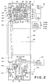
- the ring tube I includes a toroidal housing A which defines a large, generally donut-shaped interior volume.
- An anode B is mounted within the toroidal housing interior volume and extends circumferentially therearound.
- a cathode means C is disposed within the toroidal housing interior space for generating at least one beam of electrons.
- a means D selectively rotates the electron beam around the anode B .
- the anode B is a tungsten toroid having a tungsten face 10 upon which the electron beam impinges.
- the housing and the anode define an annular cooling fluid path or channel 12 in intimate thermal communication with the anode face, specifically along an opposite surface of the anode.
- the anode can be a large continuous member or assembled form multiple sections.
- the anode can have internal passages, fins, and the like to promote thermal communication with the cooling fluid.
- a fluid circulating means 14 circulates the fluid through the stationary anode and housing to a heat exchanger 16 to keep the target anode cool.
- a window 20 is defined in the housing closely adjacent to the target anode B .
- the window is positioned such that an x-ray beam 22 generated by interaction of the electron beam and the tungsten target anode is directed transverse to a central axis 24 of the toroidal tube through a central bore 26 .
- the window is constructed of a sheet of stainless steel which is TIG welded in a vacuum sealed relationship to preferably steel surrounding portions of the toroidal housing A .
- the housing at least adjacent to the anode is constructed of beryllium to reduce the intensity of off-focal radiation.
- a vacuum means, preferably one or more ion pumps 28 is interconnected with the housing to maintain the vacuum within the housing.
- the cathode assembly includes an annular ring 30 which extends around the interior of the toroidal housing.
- One or more cathode cups 32 are mounted on the cathode ring.
- the cathode cups 32 each includes a cathode filament 34 .
- each of the cathode cups 32 has a preselected focus characteristic. In this manner, different dimensions of the x-ray beam focal spot are chosen by selecting among the cathode cups.
- the cathode ring 30 is rotatably supported within the housing by a bearing means 40 .
- the bearing means is a magnetic levitation bearing.
- Thin rings 42 of silicon iron or other material are longitudinally stacked to form cylinders for the radial portion of the bearing.
- Thin hoops of silicon iron or other material are assembled to form tightly nested cylinders for the axial portion of the bearing. Passive and active elements, i.e.
- a brushless, large diameter induction motor 50 includes a stator 52 stationarily mounted to the housing and a rotor 54 connected with the cathode ring. The motor causes the cathode assembly C to rotate at a selected speed through the toroidal vacuum of the housing.
- Mechanical roller bearings 56 are provided for supporting the cathode ring in the event the magnetic levitation system should fail. The mechanical roller bearings prevent the cathode ring from interacting with stationary housing and other structures.
- a laser gyro or other angular position monitoring means 58 monitors the angular position of the cathode assembly, hence the location of the apex of the x-ray beam on the anode surface.
- each cathode cup assembly 32 Adjacent each cathode cup assembly 32 , there is a support 60 which rotates with the cathode cup.
- the support 60 carries a filter or compensator 62 which is mounted to the support adjacent to the window for filtering the generated x-ray beams to provide beam hardness correction or the like.
- the filter is a shaped block of beryllium oxide (BeO).
- BeO beryllium oxide
- structures for defining fan beam angle or width may also be mounted for rotation with the cathode cup.
- a current source 70 provides an AC current for actuating the selected cathode cup.
- the AC current is passed to a stationary, annular capacitor plate 72 mounted inside the housing.
- a matching, rotating capacitor plate 74 supported by the cathode ring is mounted closely adjacent to the stationary cathode plate.
- the rotating cathode plate is electrically connected with a series of magnetically controlled switches 76 .
- Each of the switches 76 is connected by an isolation transformer 77 with one of the cathode cups or circuitry for controlling a bias to any grids on the cathode cups.
- a plurality of annular electromagnets 78 are stationarily mounted along the housing.
- An electrical control means 80 on an operator control 82 permits actuation of one or more of the electromagnets for opening and closing the magnetically controlled switches to select among the cathode cups and any biasing potentials.
- the isolation transformer 77 includes a primary winding 83 connected with the switch 76 and the annular ring 30 .
- a secondary 84 is connected with one end of the cathode filament 34 and a high voltage supply line 85 which biases the cathode cup to -100 to -200 kV.
- a ceramic insulator 86 insulates the annular ring 30 from the cathode cup and the high voltage supply line 85 .
- a filament 87 that is connected between the annular ring 30 and the current source 70 boils off electrons that are transferred to the housing. This transfers any charge accumulated on the annular ring and holds the housing and annular ring at the same potential.
- external switches provide power to one of a plurality of stationary capacitor rings.
- Each of a matching plurality of rotating rings is connected with a different cathode cup.
- the capacitive coupling may be replaced by an inductive coupling, such as a stationary annular primary winding which is mounted closely and adjacent and across an air gap from the rotating annular secondary winding.
- the anode and the cathode are maintained at a high relative voltage differential, typically on the order of 130 kV.
- the stationary housing and the anode are held at ground, for user safety.
- the rotating cathode assembly is biased on the order of -130 kV relative to the housing.
- a high voltage section 90 generates a high voltage which is applied to a hot cathode 92 of a vacuum diode assembly.
- the hot cathode filament 92 is preferably of a low work function type.
- the high voltage section 90 is a multiplicity of compact, three phase, high-frequency voltage generators 901, 902, ... 90 n connected with parallel current sharing outputs.
- Each generator has a minimal output capacitance to minimize energy storage and reduce damage if arcing should occur.
- the low capacitance also enables higher speed kV switching for dual energy applications.
- the voltage generators 90 are connected with an energy storage device 93 , such as storage batteries or capacitors. The energy storage device draws current to recharge at a relatively low rate and supplies current at a relatively high rate during an exposure.
- a circular channel of a toroidal or donut-shaped plate 94 partially surrounds the hot cathode filament.
- the toroidal plate is mounted to the cathode assembly for rotation therewith.
- a ceramic or other thermally isolating plate or means 96 isolates the toroidal plate from the rotating annular ring 30 .
- the current is conducted by the high voltage supply line 85 from the toroidal plate to the cathode cup.
- the supply line 85 is preferably a thin wire or film to limit heat transfer.
- a grid 99 is mounted around the hot cathode for filtering and tube current control.
- the housing A is again toroidal.
- the anode B is again annular and defines a cooling path 12 with a portion of the housing.
- the tungsten anode face 10 is disposed toward the cathode assembly C to generate the x-ray beam when excited by an electron beam from the cathode.
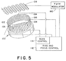
- the cathode assembly includes a multiplicity of cathode cups 100 arranged closely adjacent to each other in a ring around the housing. Each cathode cup includes a cathode filament 102 which is heated by an excitation current to undergo thermionic emission.
- a grid assembly includes a pair of grids 104 for focusing the generated electron beam in a circumferential direction relative to the anode and a pair of grids 106 for focusing the electron beam in a radial direction.
- a gate electrode 108 selectively permits and prevents the electron beam from reaching the anode.
- a switching means 110 sequentially switches each of the gate grids 108 to permit the passage of electrons. In this manner, the electron beam is stepped, or moved in other selected patterns, around the anode.
- a biasing and focusing control circuit 112 applies appropriate bias voltages to the grid pairs 104 , 106 to focus the electron beam at a selected point on the anode relative to the cathode cup with a selected beam dimension.
- the biasing and focusing control circuit 112 may include a scanning means 114 for gradually or incrementally shifting the bias voltage between the grids 104 , 106 to sweep or scan the electron beam continuously or in a plurality of steps to a plurality of positions along an arc segment of the anode commensurate with a circumferential length of the cathode cup.
- the switching means 110 switches to the next cathode cup, it causes the beam scanning means 114 to sweep the electron beam along each of its preselected circumferential beam positions.
- a high voltage means 120 biases the cathode assembly C to a high voltage relative to the housing.
- a ceramic insulation layer 122 insulates the cathode cups from the housing such that the cathode cups can be maintained at a potential, on the order of -130 kV, relative to the housing.
- the housing is preferably held to ground and the cathode cups are biased on the order of -130 kV relative to the housing and the anode.
- the anode may be electrically insulated from the housing and biased to a positive voltage relative to the housing. In such an embodiment, care must be taken that the cooling fluid is dielectric such that the cooling fluid does not short the anode to the housing.
- the filaments of all the cathode cups are preferably driven concurrently.
- the switching means 110 further switches the high voltage supply 120 sequentially to each of the cathode cups 100 . In this manner, only one or a small group of cathode cups at time is maintained at a sufficiently high voltage relative to the anode to cause an x-ray beam and the generation of x-rays.
- either the grid 108 or the individual cathode cup biasing may be used individually to control the electron and x-ray beams.
- An x-ray beam apex location means 124 determines the location of the electron beam on the anode, hence the origin of the x-ray beam, from the output of switching means 110 .
- Each individual cathode segment or cup preferably is constructed with radial slots with series or parallel connected filaments in each slot.
- Such slot and filament portions naturally provide line focus electron beams desirable for target loading when the grid voltage is removed from the desired segment.
- This radially slotted section may be divided in half and appropriately insulated to facilitate sweeping the focal spot across the anode track. These halves can also be used to alter the size of the focal spot.
- An additional refinement may be obtained by heating the filament or, more generally, the electron emitter by a second cathode structure behind the emitter and accelerated by a more modest potential and a locally controlled grid in a similar manner to the main cathode structure.
- One of the benefits achieved by this construction is that low temperature, low work function filaments may be employed. This lowers the heating current requirement substantially.
- the electron emitters can be heated very uniformly to achieve a very uniform focal spot.
- These emitters furthermore may be constructed of tungsten ribbon or other suitable shaped material of low effective thermal mass so that an emitter may be boosted to operating temperature very quickly, requiring only grid control of the second filament to achieve markedly lower heating energy to the electron emitter and a large increase in reliability.
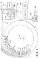
- a ring of detectors 130 are supported with a housing such that they remain stationary as the cathode assembly C rotates.
- a collimator or other off-focal radiation limiting means 132 is positioned relative to the point at which the electron beam impacts the anode such that the resultant collimated radiation beam 22 is incident on the detectors.
- the detectors are positioned as close as possible to the collimator such that the fan beam of radiation is, as close as possible, orthogonal to the central axis 24 of the ring tube.
- the x-ray beam can be defined by collimation to within a half a degree or less of orthogonal to the central axis.
- the patient and the x-ray source move relative to each other along the central axis 24 such that the detected radiation data represents generally a spiral pattern through the patient.
- a conventional volume imaging means 134 reconstructs the spiral data from the detectors using the beam apex location information into a three-dimensional image representation which is stored in a volume image memory 136 .
- spiral imaging it will be appreciated that the continuous axial movement causes each sampling of the detectors to be in a different axial position, i.e.
- the adjustments made by the conventional volume imaging means 134 to interpolate the spiral data into parallel plane data for reconstruction can also make an appropriate adjustment for the angular offset between the axis and the x-ray beam.
- a cone beam algorithm is used along with the interpolation of data.
- an analogous correction can be made.
- the image can be reconstructed using conventional planar image reconstruction algorithms without compensating for the effective increase in the width of the slice.
- the operator console 82 contains appropriate controls for withdrawing selected portions of the volume image representation from the volume image memory 136 for display on a video monitor 138 or other appropriate displays.
- the operator control means 84 may select planes along orthogonal axes through the volume image data, planes skewed to the orthogonal axes, 3D type images with appropriate surface shading to provide the two-dimensional display with the appearance of three dimensions, and the like.
- a shutter 140 is mounted for selective movement between a closed position covering the window and an open position which permits the transmission of x-rays through the window to the detector ring.
- the shutter ring is constructed of a radiation blocking material such that no radiation is permitted to pass therethrough when the shutter is closed.
- a shutter control means 142 such as a plurality of linear motors selectively slides the shutter ring between open and closed positions.
- the collimator or off-focal radiation limiting means 132 defines the x-ray beam 22 perpendicular to the central axis 24 .
- the ring of radiation detectors 130 is fixed against rotation.
- a nutating means 144 moves the portion of the radiation detectors generally parallel to the central axis 24 such that the detectors are positioned in front of the window 20 opposite the apex location of the radiation beam. That portion of the detector ring which is positioned adjacent the point at which x-rays are being generated is offset from the plane of the x-ray beam such that the x-ray beam does not pass through those detectors.
- the nutating means 144 includes a wobble-plate type construction. More specifically, an annular motor 146 rotates an annular cam surface 148 which is mounted at an angle to the central axis 24 . As the angled plate or cam surface rotates, it rotates the portion of the detector ring which is cammed into alignment with the x-ray beam.
- the detector ring can be made in segments which are moved parallel to the central axis 24 into and out of the plane of the x-ray beam.
- magnetic cams are used to produce the nutating movement.
- the x-ray beam is directed and collimated at a slight angle to the central axis 24 to impact a detector ring located near the exterior diameter of the ring tube.
- a plurality of cathode cups 32a and 32b are provided. Grids 36 filter, gate, and control the emitted electron beam.
- the cathode assembly is illustrated as being suspended by repulsive interaction with permanent magnets 42 ' rather than attractive interaction with fields induced in the silicon iron hoops.
- a large diameter annular motor 150 rotates a partial ring of x-ray detectors 130' .
- a collimator, filter, or compensating means 152 may be mounted to rotate opposite the detector arc.
- a first angular position detecting means 58 preferably a laser gyro, detects the angular position of the cathode assembly B .
- a second angular position detecting means 154 detects the angular position of the detector arc.
- a rotation controller 156 controls the operation of the motor 150 in accordance with the input from the two position detectors such that the detector arc rotates at precisely the same speed as the x-ray beam.
- the x-ray detector means 130 includes an arc of scintillation crystals 160 and a ring of opto-electrical transducers, such as photodiodes 162 .
- At least the scintillation crystal or other x-ray to light transducer means is mounted along an arc segment to the cathode assembly C opposite one or more cathode filaments.
- the arc of scintillation crystals rotates therewith.
- the photodiodes are mounted stationarily on the exterior of the housing.
- An optical coupling 164 transfers light from the rotating scintillation crystals to the stationary photodiodes as the cathode assembly rotates.
- a light amplifier is advantageously positioned between the scintillation crystals and the photodiodes.
- the scintillation crystals extend along only an arc segment such that the radiation does need to pass through the scintillation crystals before striking the patient.
- a shielding means or ring 166 is provided for shielding the optical transfer means 164 for receiving light or other incident radiation.
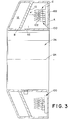
- the mounting means II includes a rotating means 170 for selectively rotating the ring tube I about a horizontal axis.
- a vertical translating means 172 selectively translates the ring tube along a vertical axis. It is to be appreciated, that the rotating means can position the ring tube horizontally such that the vertical translating means 172 translates the ring tube along a standing patient. This enables patients to be imaged in a standing orientation to reflect the natural effects of gravity on the patient's body.
- a horizontal translating means 174 selectively translates the ring tube along a horizontal direction.
- the horizontal translating means can translate the ring tube along a stationary patient in a prone position, e.g. supported on a patient couch 176 .
- the couch 176 includes a horizontal translating means 178 for moving a top surface of the couch, hence the patient, along a horizontal axis.
- the electronic section III further includes means for causing the ring tube to generate a dual or multiple energy x-ray beam.
- the dual or multiple energy means includes a grid potential modulating means 180 , such as an oscillating voltage source, for oscillating the potential applied to the gating grid of the active electron source. By modulating the gate potential voltage, the flow of electrons, hence the energy of the electron beam is selectively modulated.
- the dual energy means can include high and low energy electron sources disposed alternately around the cathode ring.
- each cathode cup 100 can include a second, lower energy filament.
- a grid is disposed around the hot cathode 92 to control the flow of energy to the cathode.
- a pilot scan means 184 selectively gates each of the electron sources to emit an electron beam as it passes a preselected point on the anode, typically top dead center. This causes a fixed orientation x-ray beam to be generated for use in pilot scans.
- the patient couch translating means 178 has a variable horizontal translation speed such that each gating of an electrode beam from the preselected point on the anode occurs in preselected steps along the patient.
- a plurality of lasers 186 are mounted on the shutter.
- the lasers emit beams of optically visible light in the plane of the window 20 for providing a visual indication of where the slice will be taken to the operator.
Applications Claiming Priority (2)
| Application Number | Priority Date | Filing Date | Title |
|---|---|---|---|
| US863182 | 1992-04-03 | ||
| US07/863,182 US5305363A (en) | 1992-01-06 | 1992-04-03 | Computerized tomographic scanner having a toroidal x-ray tube with a stationary annular anode and a rotating cathode assembly |
Publications (3)
| Publication Number | Publication Date |
|---|---|
| EP0564292A2 true EP0564292A2 (fr) | 1993-10-06 |
| EP0564292A3 EP0564292A3 (en) | 1995-03-15 |
| EP0564292B1 EP0564292B1 (fr) | 1998-12-02 |
Family
ID=25340473
Family Applications (1)
| Application Number | Title | Priority Date | Filing Date |
|---|---|---|---|
| EP93302599A Expired - Lifetime EP0564292B1 (fr) | 1992-04-03 | 1993-04-01 | Scanner CT avec tube annulaire |
Country Status (4)
| Country | Link |
|---|---|
| US (1) | US5305363A (fr) |
| EP (1) | EP0564292B1 (fr) |
| JP (1) | JP3622057B2 (fr) |
| DE (1) | DE69322303T2 (fr) |
Cited By (19)
| Publication number | Priority date | Publication date | Assignee | Title |
|---|---|---|---|---|
| EP0676911A1 (fr) * | 1994-04-08 | 1995-10-11 | Picker International, Inc. | Tube à rayons X dans un appareil de balayage pour tomographie assistée par ordinateur |
| EP0701391A1 (fr) * | 1994-09-06 | 1996-03-13 | Picker International, Inc. | Dispositifs comportant un tube à rayons X |
| EP1371330A1 (fr) * | 2001-02-23 | 2003-12-17 | Mitsubishi Heavy Industries, Ltd. | Appareil ct de rayons x et procede d'imagerie de cet appareil ct de rayons x |
| WO2003103496A1 (fr) * | 2002-06-11 | 2003-12-18 | Breakaway Imaging, Llc | Appareil de support mobile en porte-a-faux pour imagerie a rayons x |
| US6940941B2 (en) | 2002-02-15 | 2005-09-06 | Breakaway Imaging, Llc | Breakable gantry apparatus for multidimensional x-ray based imaging |
| WO2006076971A1 (fr) * | 2004-10-20 | 2006-07-27 | Siemens Aktiengesellschaft | Tomodensitometre a transmission electrique sans contact simultanee d'une tension d'alimentation et de donnees de mesure et de commande |
| US7106825B2 (en) | 2002-08-21 | 2006-09-12 | Breakaway Imaging, Llc | Apparatus and method for reconstruction of volumetric images in a divergent scanning computed tomography system |
| US7108421B2 (en) | 2002-03-19 | 2006-09-19 | Breakaway Imaging, Llc | Systems and methods for imaging large field-of-view objects |
| US7188998B2 (en) | 2002-03-13 | 2007-03-13 | Breakaway Imaging, Llc | Systems and methods for quasi-simultaneous multi-planar x-ray imaging |
| US7338207B2 (en) | 2002-08-21 | 2008-03-04 | Medtronic Navigation, Inc. | Gantry positioning apparatus for X-ray imaging |
| DE102007041107A1 (de) * | 2007-08-30 | 2009-03-05 | Siemens Ag | Röntgengerät |
| EP2079083A2 (fr) * | 2008-01-08 | 2009-07-15 | Poskom Co., ltd. | Dispositif à rayons X compact et léger |
| GB2479701B (en) * | 2009-03-12 | 2015-12-09 | Cxr Ltd | X-ray scanners and X-ray sources therefor |
| US9618648B2 (en) | 2003-04-25 | 2017-04-11 | Rapiscan Systems, Inc. | X-ray scanners |
| US9638646B2 (en) | 2005-12-16 | 2017-05-02 | Rapiscan Systems, Inc. | X-ray scanners and X-ray sources therefor |
| US9899142B2 (en) | 2014-06-23 | 2018-02-20 | Shanghai United Imaging Healthcare Co., Ltd | Method and device for insulation of high-voltage generator tank |
| US10295483B2 (en) | 2005-12-16 | 2019-05-21 | Rapiscan Systems, Inc. | Data collection, processing and storage systems for X-ray tomographic images |
| US10591424B2 (en) | 2003-04-25 | 2020-03-17 | Rapiscan Systems, Inc. | X-ray tomographic inspection systems for the identification of specific target items |
| CN113433579A (zh) * | 2021-05-18 | 2021-09-24 | 中国工程物理研究院激光聚变研究中心 | 一种大灵敏面x射线光谱平响应二极管探测器 |
Families Citing this family (77)
| Publication number | Priority date | Publication date | Assignee | Title |
|---|---|---|---|---|
| JP3256579B2 (ja) * | 1992-09-18 | 2002-02-12 | 株式会社島津製作所 | 回転陰極x線管装置 |
| US5602897A (en) * | 1995-06-29 | 1997-02-11 | Picker International, Inc. | High-voltage power supply for x-ray tubes |
| US6089311A (en) * | 1995-07-05 | 2000-07-18 | Borealis Technical Limited | Method and apparatus for vacuum diode heat pump |
| US5722242A (en) * | 1995-12-15 | 1998-03-03 | Borealis Technical Limited | Method and apparatus for improved vacuum diode heat pump |
| US5675972A (en) * | 1996-09-25 | 1997-10-14 | Borealis Technical Limited | Method and apparatus for vacuum diode-based devices with electride-coated electrodes |
| US6256364B1 (en) | 1998-11-24 | 2001-07-03 | General Electric Company | Methods and apparatus for correcting for x-ray beam movement |
| US6125167A (en) * | 1998-11-25 | 2000-09-26 | Picker International, Inc. | Rotating anode x-ray tube with multiple simultaneously emitting focal spots |
| US6229870B1 (en) | 1998-11-25 | 2001-05-08 | Picker International, Inc. | Multiple fan beam computed tomography system |
| US6735274B1 (en) | 2000-02-15 | 2004-05-11 | Koninklijke Philips Electronics N.V. | Clinical screening CT systems |
| US7227924B2 (en) * | 2000-10-06 | 2007-06-05 | The University Of North Carolina At Chapel Hill | Computed tomography scanning system and method using a field emission x-ray source |
| US7082182B2 (en) * | 2000-10-06 | 2006-07-25 | The University Of North Carolina At Chapel Hill | Computed tomography system for imaging of human and small animal |
| US7085351B2 (en) * | 2000-10-06 | 2006-08-01 | University Of North Carolina At Chapel Hill | Method and apparatus for controlling electron beam current |
| US6876724B2 (en) * | 2000-10-06 | 2005-04-05 | The University Of North Carolina - Chapel Hill | Large-area individually addressable multi-beam x-ray system and method of forming same |
| US6483890B1 (en) * | 2000-12-01 | 2002-11-19 | Koninklijke Philips Electronics, N.V. | Digital x-ray imaging apparatus with a multiple position irradiation source and improved spatial resolution |
| DE10143749A1 (de) * | 2001-09-06 | 2003-06-18 | Siemens Ag | Bildgebendes medizinisches Untersuchungsgerät |
| US7813473B2 (en) * | 2002-07-23 | 2010-10-12 | General Electric Company | Method and apparatus for generating temporally interpolated projections |
| US6904118B2 (en) * | 2002-07-23 | 2005-06-07 | General Electric Company | Method and apparatus for generating a density map using dual-energy CT |
| DE10240628B4 (de) * | 2002-09-03 | 2012-06-21 | Siemens Ag | Röntgenröhre mit Ringanode und Röntgen-System mit einer solchen Röntgenröhre |
| DE10312048B4 (de) * | 2002-11-18 | 2005-01-20 | Benjamin Holch | Computertomograph |
| US7031425B2 (en) * | 2002-11-27 | 2006-04-18 | Ge Medical Systems Global Technology Company, Llc | Methods and apparatus for generating CT scout images |
| US9208988B2 (en) | 2005-10-25 | 2015-12-08 | Rapiscan Systems, Inc. | Graphite backscattered electron shield for use in an X-ray tube |
| US9113839B2 (en) | 2003-04-25 | 2015-08-25 | Rapiscon Systems, Inc. | X-ray inspection system and method |
| GB0812864D0 (en) | 2008-07-15 | 2008-08-20 | Cxr Ltd | Coolign anode |
| US8094784B2 (en) | 2003-04-25 | 2012-01-10 | Rapiscan Systems, Inc. | X-ray sources |
| US10483077B2 (en) | 2003-04-25 | 2019-11-19 | Rapiscan Systems, Inc. | X-ray sources having reduced electron scattering |
| US7492855B2 (en) * | 2003-08-07 | 2009-02-17 | General Electric Company | System and method for detecting an object |
| US7889835B2 (en) * | 2003-08-07 | 2011-02-15 | Morpho Detection, Inc. | System and method for detecting an object by dynamically adjusting computational load |
| US7280631B2 (en) * | 2003-11-26 | 2007-10-09 | General Electric Company | Stationary computed tomography system and method |
| US20050226364A1 (en) * | 2003-11-26 | 2005-10-13 | General Electric Company | Rotational computed tomography system and method |
| US20050117706A1 (en) * | 2003-12-01 | 2005-06-02 | Powell David L. | Cooling and power system for a medical imaging system |
| US7639774B2 (en) * | 2003-12-23 | 2009-12-29 | General Electric Company | Method and apparatus for employing multiple axial-sources |
| US7333587B2 (en) | 2004-02-27 | 2008-02-19 | General Electric Company | Method and system for imaging using multiple offset X-ray emission points |
| JP2005288152A (ja) * | 2004-03-31 | 2005-10-20 | General Electric Co <Ge> | 回転コンピュータ断層撮影のシステム及び方法 |
| FR2870428A1 (fr) * | 2004-05-11 | 2005-11-18 | Gen Electric | Machine a rayons x mobile |
| US7227923B2 (en) * | 2005-04-18 | 2007-06-05 | General Electric Company | Method and system for CT imaging using a distributed X-ray source and interpolation based reconstruction |
| US8155262B2 (en) * | 2005-04-25 | 2012-04-10 | The University Of North Carolina At Chapel Hill | Methods, systems, and computer program products for multiplexing computed tomography |
| US7295651B2 (en) * | 2005-06-30 | 2007-11-13 | General Electric Company | Stationary computed tomography system and method |
| US20070076842A1 (en) * | 2005-09-30 | 2007-04-05 | Tkaczyk John E | Adaptable energy discriminating computed tomography system |
| US9046465B2 (en) | 2011-02-24 | 2015-06-02 | Rapiscan Systems, Inc. | Optimization of the source firing pattern for X-ray scanning systems |
| US8189893B2 (en) * | 2006-05-19 | 2012-05-29 | The University Of North Carolina At Chapel Hill | Methods, systems, and computer program products for binary multiplexing x-ray radiography |
| US7706499B2 (en) * | 2006-08-30 | 2010-04-27 | General Electric Company | Acquisition and reconstruction of projection data using a stationary CT geometry |
| US20080056432A1 (en) * | 2006-08-30 | 2008-03-06 | General Electric Company | Reconstruction of CT projection data |
| US7616731B2 (en) * | 2006-08-30 | 2009-11-10 | General Electric Company | Acquisition and reconstruction of projection data using a stationary CT geometry |
| US7835486B2 (en) * | 2006-08-30 | 2010-11-16 | General Electric Company | Acquisition and reconstruction of projection data using a stationary CT geometry |
| DE102007008349B4 (de) * | 2007-02-20 | 2009-10-15 | Forschungszentrum Dresden - Rossendorf E.V. | Anordnung zur Röntgen-Computertomographie |
| CN101842052B (zh) * | 2007-07-19 | 2013-11-20 | 北卡罗来纳大学查珀尔希尔分校 | 固定x射线数字化乳房断层合成系统和相关方法 |
| DE102007035177A1 (de) * | 2007-07-27 | 2009-02-05 | Siemens Ag | Computertomographie-System mit feststehendem Anodenring |
| DE102007036038A1 (de) * | 2007-08-01 | 2009-02-05 | Siemens Ag | Röntgen-Computertomograph der 5ten Generation |
| US8076943B2 (en) * | 2008-02-21 | 2011-12-13 | Genesis Medical Imaging, Inc. | Impedance-based arc detector for computed tomography scanner and method of use thereof |
| DE102008034584A1 (de) * | 2008-07-24 | 2010-02-04 | Siemens Aktiengesellschaft | Röntgen-Computertomograph |
| GB0816823D0 (en) | 2008-09-13 | 2008-10-22 | Cxr Ltd | X-ray tubes |
| US8600003B2 (en) * | 2009-01-16 | 2013-12-03 | The University Of North Carolina At Chapel Hill | Compact microbeam radiation therapy systems and methods for cancer treatment and research |
| FR2941587B1 (fr) * | 2009-01-28 | 2011-03-04 | Gen Electric | Alimentation electrique d'un tube a rayons x, procede d'alimentation et systeme d'imagerie associes |
| GB0901338D0 (en) | 2009-01-28 | 2009-03-11 | Cxr Ltd | X-Ray tube electron sources |
| US8259905B2 (en) * | 2009-05-18 | 2012-09-04 | King Fahd University Of Petroleum And Minerals | X-ray tube having a rotating and linearly translating anode |
| US7852987B2 (en) | 2009-05-18 | 2010-12-14 | King Fahd University Of Petroleum And Minerals | X-ray tube having a rotating and linearly translating anode |
| CN102802532A (zh) * | 2009-06-18 | 2012-11-28 | 皇家飞利浦电子股份有限公司 | 具有环境安全壳的移动成像单元 |
| US8270563B2 (en) * | 2010-02-09 | 2012-09-18 | Aktiebolaget Skf | Diagnostic scanning apparatus |
| US8358739B2 (en) | 2010-09-03 | 2013-01-22 | The University Of North Carolina At Chapel Hill | Systems and methods for temporal multiplexing X-ray imaging |
| USD669184S1 (en) * | 2011-08-29 | 2012-10-16 | General Electric Company | Pink ribbon arm |
| DE102012201529B4 (de) * | 2011-10-28 | 2014-06-26 | Siemens Aktiengesellschaft | Vorrichtung, aufweisend eine linear verstellbare Gantry eines Computertomographiegerätes |
| DE102012213875B4 (de) * | 2012-08-06 | 2019-12-24 | Siemens Healthcare Gmbh | Versorgungseinheit für eine verfahrbare Gantry |
| US9208986B2 (en) | 2012-11-08 | 2015-12-08 | General Electric Company | Systems and methods for monitoring and controlling an electron beam |
| US9237872B2 (en) | 2013-01-18 | 2016-01-19 | General Electric Company | X-ray source with moving anode or cathode |
| US9538963B2 (en) | 2013-03-15 | 2017-01-10 | Aktiebolaget Skf | Diagnostic scanning apparatus |
| US10328513B2 (en) | 2013-05-31 | 2019-06-25 | General Electric Company | Welding process, welding system, and welded article |
| WO2015019232A2 (fr) * | 2013-08-08 | 2015-02-12 | Controlrad Systems Inc. | Système de réduction des rayons x |
| US9782136B2 (en) | 2014-06-17 | 2017-10-10 | The University Of North Carolina At Chapel Hill | Intraoral tomosynthesis systems, methods, and computer readable media for dental imaging |
| US10980494B2 (en) | 2014-10-20 | 2021-04-20 | The University Of North Carolina At Chapel Hill | Systems and related methods for stationary digital chest tomosynthesis (s-DCT) imaging |
| US10405813B2 (en) * | 2015-02-04 | 2019-09-10 | Dental Imaging Technologies Corporation | Panoramic imaging using multi-spectral X-ray source |
| US10113981B2 (en) | 2015-07-21 | 2018-10-30 | Lockheed Martin Corporation | Real-time analysis and control of electron beam manufacturing process through x-ray computed tomography |
| WO2017194727A1 (fr) * | 2016-05-13 | 2017-11-16 | Koninklijke Philips N.V. | Système et procédé d'exposition à des rayons x multi-faisceaux pour une imagerie 4d |
| EP3696845A1 (fr) * | 2019-02-12 | 2020-08-19 | Malvern Panalytical B.V. | Tube à rayons x et système d'analyse à rayons x |
| DE202019001877U1 (de) * | 2019-04-27 | 2020-07-28 | Bec Gmbh | Patientenbestrahlungseinrichtung |
| EP3933881A1 (fr) | 2020-06-30 | 2022-01-05 | VEC Imaging GmbH & Co. KG | Source de rayons x à plusieurs réseaux |
| JP2022143666A (ja) * | 2021-03-18 | 2022-10-03 | コニカミノルタ株式会社 | 放射線撮影装置 |
| DE102022210342A1 (de) * | 2022-09-29 | 2024-04-04 | Siemens Healthineers Ag | Untersuchungsraum mit CT-Anlage mit verbesserter Kabelführung |
Citations (9)
| Publication number | Priority date | Publication date | Assignee | Title |
|---|---|---|---|---|
| DE2650237A1 (de) * | 1976-11-02 | 1978-05-11 | Siemens Ag | Roentgendiagnostikgeraet zur herstellung von transversalschichtbildern |
| EP0005666A1 (fr) * | 1978-05-16 | 1979-11-28 | Thomson-Csf | Appareil tomographique à gaine unique |
| US4227088A (en) * | 1978-10-10 | 1980-10-07 | Bell Telephone Laboratories, Incorporated | High speed computer assisted tomography |
| US4274005A (en) * | 1978-09-29 | 1981-06-16 | Tokyo Shibaura Denki Kabushiki Kaisha | X-ray apparatus for computed tomography scanner |
| US4288695A (en) * | 1979-04-13 | 1981-09-08 | Technicare Corporation | Computerized tomographic scanner with shaped radiation filter |
| US4300051A (en) * | 1978-06-29 | 1981-11-10 | Spire Corporation | Traveling cathode X-ray source |
| DE4015180A1 (de) * | 1990-05-11 | 1991-11-28 | Bruker Analytische Messtechnik | Roentgen-computer-tomographie-system mit geteiltem detektorring |
| EP0466956A1 (fr) * | 1990-07-18 | 1992-01-22 | Siemens Aktiengesellschaft | Appareil de tomographie |
| EP0456114B1 (fr) * | 1990-04-30 | 1994-12-07 | Shimadzu Corporation | Tube à rayons X pour dispositif de tomographie |
Family Cites Families (13)
| Publication number | Priority date | Publication date | Assignee | Title |
|---|---|---|---|---|
| GB1568782A (en) * | 1976-02-28 | 1980-06-04 | Jeol Ltd | Apparatus for obtaining an x-ray image of a slice plane of an object |
| US4122346A (en) * | 1977-03-23 | 1978-10-24 | High Voltage Engineering Corporation | Optical devices for computed transaxial tomography |
| DE2750551C2 (de) * | 1977-11-11 | 1985-11-21 | Siemens AG, 1000 Berlin und 8000 München | Computertomograph |
| DE3043046A1 (de) * | 1980-11-14 | 1982-07-15 | Siemens AG, 1000 Berlin und 8000 München | Drehanoden-roentgenroehre |
| NL8502533A (nl) * | 1985-09-17 | 1987-04-16 | Philips Nv | Roentgenscanner met een lineaire electrische aandrijfmotor. |
| US4821305A (en) * | 1986-03-25 | 1989-04-11 | Varian Associates, Inc. | Photoelectric X-ray tube |
| JPS6321040A (ja) * | 1986-07-16 | 1988-01-28 | 工業技術院長 | 超高速x線ctスキヤナ |
| IL88904A0 (en) * | 1989-01-06 | 1989-08-15 | Yehuda Elyada | X-ray tube apparatus |
| SU1635090A1 (ru) * | 1989-04-25 | 1991-03-15 | Научно-исследовательский институт интроскопии при Томском политехническом институте им.С.М.Кирова | Вычислительный томограф |
| JPH03226950A (ja) * | 1990-01-30 | 1991-10-07 | Eruyada Ehuda | X線管装置 |
| EP0455177A3 (en) * | 1990-04-30 | 1992-05-20 | Shimadzu Corporation | High-speed scan type x-ray generator |
| US5200985A (en) * | 1992-01-06 | 1993-04-06 | Picker International, Inc. | X-ray tube with capacitively coupled filament drive |
| US5241577A (en) * | 1992-01-06 | 1993-08-31 | Picker International, Inc. | X-ray tube with bearing slip ring |
-
1992
- 1992-04-03 US US07/863,182 patent/US5305363A/en not_active Expired - Lifetime
-
1993
- 1993-03-30 JP JP09545693A patent/JP3622057B2/ja not_active Expired - Fee Related
- 1993-04-01 DE DE69322303T patent/DE69322303T2/de not_active Expired - Fee Related
- 1993-04-01 EP EP93302599A patent/EP0564292B1/fr not_active Expired - Lifetime
Patent Citations (9)
| Publication number | Priority date | Publication date | Assignee | Title |
|---|---|---|---|---|
| DE2650237A1 (de) * | 1976-11-02 | 1978-05-11 | Siemens Ag | Roentgendiagnostikgeraet zur herstellung von transversalschichtbildern |
| EP0005666A1 (fr) * | 1978-05-16 | 1979-11-28 | Thomson-Csf | Appareil tomographique à gaine unique |
| US4300051A (en) * | 1978-06-29 | 1981-11-10 | Spire Corporation | Traveling cathode X-ray source |
| US4274005A (en) * | 1978-09-29 | 1981-06-16 | Tokyo Shibaura Denki Kabushiki Kaisha | X-ray apparatus for computed tomography scanner |
| US4227088A (en) * | 1978-10-10 | 1980-10-07 | Bell Telephone Laboratories, Incorporated | High speed computer assisted tomography |
| US4288695A (en) * | 1979-04-13 | 1981-09-08 | Technicare Corporation | Computerized tomographic scanner with shaped radiation filter |
| EP0456114B1 (fr) * | 1990-04-30 | 1994-12-07 | Shimadzu Corporation | Tube à rayons X pour dispositif de tomographie |
| DE4015180A1 (de) * | 1990-05-11 | 1991-11-28 | Bruker Analytische Messtechnik | Roentgen-computer-tomographie-system mit geteiltem detektorring |
| EP0466956A1 (fr) * | 1990-07-18 | 1992-01-22 | Siemens Aktiengesellschaft | Appareil de tomographie |
Non-Patent Citations (1)
| Title |
|---|
| IEEE Transactions on Nuclear Science, vol. NS-26, April 1979 MAYDAN et al. "A New Design for High Speed Computerized Tomography" pages 2870-2871 * |
Cited By (45)
| Publication number | Priority date | Publication date | Assignee | Title |
|---|---|---|---|---|
| US5475729A (en) * | 1994-04-08 | 1995-12-12 | Picker International, Inc. | X-ray reference channel and x-ray control circuit for ring tube CT scanners |
| EP0676911A1 (fr) * | 1994-04-08 | 1995-10-11 | Picker International, Inc. | Tube à rayons X dans un appareil de balayage pour tomographie assistée par ordinateur |
| EP0701391A1 (fr) * | 1994-09-06 | 1996-03-13 | Picker International, Inc. | Dispositifs comportant un tube à rayons X |
| EP1371330A4 (fr) * | 2001-02-23 | 2006-12-20 | Mitsubishi Heavy Ind Ltd | Appareil ct de rayons x et procede d'imagerie de cet appareil ct de rayons x |
| EP1371330A1 (fr) * | 2001-02-23 | 2003-12-17 | Mitsubishi Heavy Industries, Ltd. | Appareil ct de rayons x et procede d'imagerie de cet appareil ct de rayons x |
| US6940941B2 (en) | 2002-02-15 | 2005-09-06 | Breakaway Imaging, Llc | Breakable gantry apparatus for multidimensional x-ray based imaging |
| US8746973B2 (en) | 2002-03-13 | 2014-06-10 | Medtronic Navigation, Inc. | Systems and methods for quasi-simultaneous multi-planar x-ray imaging |
| US7188998B2 (en) | 2002-03-13 | 2007-03-13 | Breakaway Imaging, Llc | Systems and methods for quasi-simultaneous multi-planar x-ray imaging |
| US9398886B2 (en) | 2002-03-19 | 2016-07-26 | Medtronic Navigation, Inc. | Systems and methods for imaging large field-of-view objects |
| US7108421B2 (en) | 2002-03-19 | 2006-09-19 | Breakaway Imaging, Llc | Systems and methods for imaging large field-of-view objects |
| US9724058B2 (en) | 2002-03-19 | 2017-08-08 | Medtronic Navigation, Inc. | Systems and methods for imaging large field-of-view objects |
| USRE49349E1 (en) | 2002-03-19 | 2022-12-27 | Medtronic Navigation, Inc. | Systems and methods for imaging large field-of-view objects |
| US8678647B2 (en) | 2002-03-19 | 2014-03-25 | Medtronic Navigation, Inc. | Systems and methods for imaging large field-of-view objects |
| US7661881B2 (en) | 2002-03-19 | 2010-02-16 | Medtronic Navigation, Inc. | Systems and methods for imaging large field-of-view objects |
| US7905659B2 (en) | 2002-06-11 | 2011-03-15 | Medtronic Navigation, Inc. | Cantilevered gantry apparatus for x-ray imaging |
| US7001045B2 (en) | 2002-06-11 | 2006-02-21 | Breakaway Imaging, Llc | Cantilevered gantry apparatus for x-ray imaging |
| US8308361B2 (en) | 2002-06-11 | 2012-11-13 | Medtronic Navigation, Inc. | Cantilevered gantry apparatus for X-ray imaging |
| WO2003103496A1 (fr) * | 2002-06-11 | 2003-12-18 | Breakaway Imaging, Llc | Appareil de support mobile en porte-a-faux pour imagerie a rayons x |
| US7965811B1 (en) | 2002-08-21 | 2011-06-21 | Medtronic Navigation, Inc. | Apparatus and method for reconstruction of volumetric images in a divergent scanning computed tomography system |
| US7338207B2 (en) | 2002-08-21 | 2008-03-04 | Medtronic Navigation, Inc. | Gantry positioning apparatus for X-ray imaging |
| US7903779B2 (en) | 2002-08-21 | 2011-03-08 | Medtronic Navigation, Inc. | Apparatus and method for reconstruction of volumetric images in a divergent scanning computed tomography system |
| US7106825B2 (en) | 2002-08-21 | 2006-09-12 | Breakaway Imaging, Llc | Apparatus and method for reconstruction of volumetric images in a divergent scanning computed tomography system |
| US7490982B2 (en) | 2002-08-21 | 2009-02-17 | Medtronic Navigation, Inc. | Gantry positioning apparatus for x-ray imaging |
| US11796711B2 (en) | 2003-04-25 | 2023-10-24 | Rapiscan Systems, Inc. | Modular CT scanning system |
| US10175381B2 (en) | 2003-04-25 | 2019-01-08 | Rapiscan Systems, Inc. | X-ray scanners having source points with less than a predefined variation in brightness |
| US10901112B2 (en) | 2003-04-25 | 2021-01-26 | Rapiscan Systems, Inc. | X-ray scanning system with stationary x-ray sources |
| US9618648B2 (en) | 2003-04-25 | 2017-04-11 | Rapiscan Systems, Inc. | X-ray scanners |
| US10591424B2 (en) | 2003-04-25 | 2020-03-17 | Rapiscan Systems, Inc. | X-ray tomographic inspection systems for the identification of specific target items |
| WO2006076971A1 (fr) * | 2004-10-20 | 2006-07-27 | Siemens Aktiengesellschaft | Tomodensitometre a transmission electrique sans contact simultanee d'une tension d'alimentation et de donnees de mesure et de commande |
| US7899150B2 (en) | 2004-10-20 | 2011-03-01 | Siemens Aktiengesellschaft | Computed tomography device including transmitters for contactless transmission of data and electrical power |
| US9638646B2 (en) | 2005-12-16 | 2017-05-02 | Rapiscan Systems, Inc. | X-ray scanners and X-ray sources therefor |
| US10976271B2 (en) | 2005-12-16 | 2021-04-13 | Rapiscan Systems, Inc. | Stationary tomographic X-ray imaging systems for automatically sorting objects based on generated tomographic images |
| US10295483B2 (en) | 2005-12-16 | 2019-05-21 | Rapiscan Systems, Inc. | Data collection, processing and storage systems for X-ray tomographic images |
| DE102007041107A1 (de) * | 2007-08-30 | 2009-03-05 | Siemens Ag | Röntgengerät |
| DE102007041107B4 (de) * | 2007-08-30 | 2009-10-29 | Siemens Ag | Röntgengerät |
| EP2079083A2 (fr) * | 2008-01-08 | 2009-07-15 | Poskom Co., ltd. | Dispositif à rayons X compact et léger |
| US8011829B2 (en) | 2008-01-08 | 2011-09-06 | Poskom Co., Ltd. | Compact and lightweight X-ray device |
| EP2079083A3 (fr) * | 2008-01-08 | 2010-08-18 | Poskom Co., ltd. | Dispositif à rayons X compact et léger |
| GB2479701B (en) * | 2009-03-12 | 2015-12-09 | Cxr Ltd | X-ray scanners and X-ray sources therefor |
| US9899142B2 (en) | 2014-06-23 | 2018-02-20 | Shanghai United Imaging Healthcare Co., Ltd | Method and device for insulation of high-voltage generator tank |
| US10340075B2 (en) | 2014-06-23 | 2019-07-02 | Shanghai United Imaging Healthcare Co., Ltd. | Method and device for insulation of high-voltage generator tank |
| US10825603B2 (en) | 2014-06-23 | 2020-11-03 | Shanghai United Imaging Healthcare Co., Ltd. | Method and device for insulation of high-voltage generator tank |
| US11923127B2 (en) | 2014-06-23 | 2024-03-05 | Shanghai United Imaging Healthcare Co., Ltd. | Method and device for insulation of high-voltage generator tank |
| CN113433579A (zh) * | 2021-05-18 | 2021-09-24 | 中国工程物理研究院激光聚变研究中心 | 一种大灵敏面x射线光谱平响应二极管探测器 |
| CN113433579B (zh) * | 2021-05-18 | 2023-01-20 | 中国工程物理研究院激光聚变研究中心 | 一种大灵敏面x射线光谱平响应二极管探测器 |
Also Published As
| Publication number | Publication date |
|---|---|
| JP3622057B2 (ja) | 2005-02-23 |
| JPH0622947A (ja) | 1994-02-01 |
| EP0564292B1 (fr) | 1998-12-02 |
| DE69322303D1 (de) | 1999-01-14 |
| US5305363A (en) | 1994-04-19 |
| EP0564292A3 (en) | 1995-03-15 |
| DE69322303T2 (de) | 1999-05-20 |
Similar Documents
| Publication | Publication Date | Title |
|---|---|---|
| US5305363A (en) | Computerized tomographic scanner having a toroidal x-ray tube with a stationary annular anode and a rotating cathode assembly | |
| US5268955A (en) | Ring tube x-ray source | |
| US5438605A (en) | Ring tube x-ray source with active vacuum pumping | |
| EP0701391B1 (fr) | Dispositifs comportant un tube à rayons X | |
| US7012989B2 (en) | Multiple grooved x-ray generator | |
| JP5647607B2 (ja) | マルチセグメント陽極ターゲットを備えた回転陽極を有するx線管、及びそれを有するx線スキャナシステム | |
| CN102088909B (zh) | 具有有效阳极散热的x射线系统 | |
| US6385292B1 (en) | Solid-state CT system and method | |
| US20020126798A1 (en) | Dual filament, electrostatically controlled focal spot for x-ray tubes | |
| EP0676911B1 (fr) | Tube à rayons X dans un appareil de balayage pour tomographie assistée par ordinateur | |
| EP0473852A1 (fr) | Tube à rayons X tournant avec des paliers externes | |
| JP2002352755A (ja) | フラットパネルx線源を備えるx線撮影装置 | |
| EP0917176B1 (fr) | Assemblage de palier pour tube à rayons X à anode tournante | |
| JP4267180B2 (ja) | X線ct装置 | |
| JPS631698B2 (fr) | ||
| JP3030069B2 (ja) | X線管 | |
| Maydan et al. | A new design for high speed computerized tomography | |
| JPH04212335A (ja) | 回転陰極x線管装置 | |
| JPH04227237A (ja) | Ct装置用x線管 | |
| JP2001292988A (ja) | カソードスキャン型x線発生器及びx線ctスキャナ |
Legal Events
| Date | Code | Title | Description |
|---|---|---|---|
| PUAI | Public reference made under article 153(3) epc to a published international application that has entered the european phase |
Free format text: ORIGINAL CODE: 0009012 |
|
| AK | Designated contracting states |
Kind code of ref document: A2 Designated state(s): DE FR GB NL |
|
| PUAL | Search report despatched |
Free format text: ORIGINAL CODE: 0009013 |
|
| AK | Designated contracting states |
Kind code of ref document: A3 Designated state(s): DE FR GB NL |
|
| 17P | Request for examination filed |
Effective date: 19950502 |
|
| 17Q | First examination report despatched |
Effective date: 19970110 |
|
| GRAG | Despatch of communication of intention to grant |
Free format text: ORIGINAL CODE: EPIDOS AGRA |
|
| GRAG | Despatch of communication of intention to grant |
Free format text: ORIGINAL CODE: EPIDOS AGRA |
|
| GRAH | Despatch of communication of intention to grant a patent |
Free format text: ORIGINAL CODE: EPIDOS IGRA |
|
| RBV | Designated contracting states (corrected) |
Designated state(s): DE FR NL |
|
| GRAH | Despatch of communication of intention to grant a patent |
Free format text: ORIGINAL CODE: EPIDOS IGRA |
|
| GRAA | (expected) grant |
Free format text: ORIGINAL CODE: 0009210 |
|
| AK | Designated contracting states |
Kind code of ref document: B1 Designated state(s): DE FR NL |
|
| ET | Fr: translation filed | ||
| REF | Corresponds to: |
Ref document number: 69322303 Country of ref document: DE Date of ref document: 19990114 |
|
| PLBE | No opposition filed within time limit |
Free format text: ORIGINAL CODE: 0009261 |
|
| STAA | Information on the status of an ep patent application or granted ep patent |
Free format text: STATUS: NO OPPOSITION FILED WITHIN TIME LIMIT |
|
| 26N | No opposition filed | ||
| PGFP | Annual fee paid to national office [announced via postgrant information from national office to epo] |
Ref country code: NL Payment date: 20030318 Year of fee payment: 11 |
|
| REG | Reference to a national code |
Ref country code: FR Ref legal event code: CD |
|
| REG | Reference to a national code |
Ref country code: FR Ref legal event code: TP |
|
| PG25 | Lapsed in a contracting state [announced via postgrant information from national office to epo] |
Ref country code: NL Free format text: LAPSE BECAUSE OF NON-PAYMENT OF DUE FEES Effective date: 20041101 |
|
| NLV4 | Nl: lapsed or anulled due to non-payment of the annual fee |
Effective date: 20041101 |
|
| PGFP | Annual fee paid to national office [announced via postgrant information from national office to epo] |
Ref country code: DE Payment date: 20070612 Year of fee payment: 15 |
|
| PGFP | Annual fee paid to national office [announced via postgrant information from national office to epo] |
Ref country code: FR Payment date: 20070425 Year of fee payment: 15 |
|
| PG25 | Lapsed in a contracting state [announced via postgrant information from national office to epo] |
Ref country code: DE Free format text: LAPSE BECAUSE OF NON-PAYMENT OF DUE FEES Effective date: 20081101 |
|
| REG | Reference to a national code |
Ref country code: FR Ref legal event code: ST Effective date: 20081231 |
|
| PG25 | Lapsed in a contracting state [announced via postgrant information from national office to epo] |
Ref country code: FR Free format text: LAPSE BECAUSE OF NON-PAYMENT OF DUE FEES Effective date: 20080430 |