EP0563575A2 - Procédé et dispositif de production en continu d'un tube composite avec manchon - Google Patents
Procédé et dispositif de production en continu d'un tube composite avec manchon Download PDFInfo
- Publication number
- EP0563575A2 EP0563575A2 EP93103013A EP93103013A EP0563575A2 EP 0563575 A2 EP0563575 A2 EP 0563575A2 EP 93103013 A EP93103013 A EP 93103013A EP 93103013 A EP93103013 A EP 93103013A EP 0563575 A2 EP0563575 A2 EP 0563575A2
- Authority
- EP
- European Patent Office
- Prior art keywords
- nozzle
- pipe
- hose
- tube
- production
- Prior art date
- Legal status (The legal status is an assumption and is not a legal conclusion. Google has not performed a legal analysis and makes no representation as to the accuracy of the status listed.)
- Granted
Links
Images


Classifications
-
- B—PERFORMING OPERATIONS; TRANSPORTING
- B29—WORKING OF PLASTICS; WORKING OF SUBSTANCES IN A PLASTIC STATE IN GENERAL
- B29C—SHAPING OR JOINING OF PLASTICS; SHAPING OF MATERIAL IN A PLASTIC STATE, NOT OTHERWISE PROVIDED FOR; AFTER-TREATMENT OF THE SHAPED PRODUCTS, e.g. REPAIRING
- B29C49/00—Blow-moulding, i.e. blowing a preform or parison to a desired shape within a mould; Apparatus therefor
- B29C49/0031—Making articles having hollow walls
-
- B—PERFORMING OPERATIONS; TRANSPORTING
- B29—WORKING OF PLASTICS; WORKING OF SUBSTANCES IN A PLASTIC STATE IN GENERAL
- B29C—SHAPING OR JOINING OF PLASTICS; SHAPING OF MATERIAL IN A PLASTIC STATE, NOT OTHERWISE PROVIDED FOR; AFTER-TREATMENT OF THE SHAPED PRODUCTS, e.g. REPAIRING
- B29C48/00—Extrusion moulding, i.e. expressing the moulding material through a die or nozzle which imparts the desired form; Apparatus therefor
- B29C48/03—Extrusion moulding, i.e. expressing the moulding material through a die or nozzle which imparts the desired form; Apparatus therefor characterised by the shape of the extruded material at extrusion
- B29C48/09—Articles with cross-sections having partially or fully enclosed cavities, e.g. pipes or channels
- B29C48/11—Articles with cross-sections having partially or fully enclosed cavities, e.g. pipes or channels comprising two or more partially or fully enclosed cavities, e.g. honeycomb-shaped
-
- B—PERFORMING OPERATIONS; TRANSPORTING
- B29—WORKING OF PLASTICS; WORKING OF SUBSTANCES IN A PLASTIC STATE IN GENERAL
- B29C—SHAPING OR JOINING OF PLASTICS; SHAPING OF MATERIAL IN A PLASTIC STATE, NOT OTHERWISE PROVIDED FOR; AFTER-TREATMENT OF THE SHAPED PRODUCTS, e.g. REPAIRING
- B29C48/00—Extrusion moulding, i.e. expressing the moulding material through a die or nozzle which imparts the desired form; Apparatus therefor
- B29C48/03—Extrusion moulding, i.e. expressing the moulding material through a die or nozzle which imparts the desired form; Apparatus therefor characterised by the shape of the extruded material at extrusion
- B29C48/13—Articles with a cross-section varying in the longitudinal direction, e.g. corrugated pipes
-
- B—PERFORMING OPERATIONS; TRANSPORTING
- B29—WORKING OF PLASTICS; WORKING OF SUBSTANCES IN A PLASTIC STATE IN GENERAL
- B29C—SHAPING OR JOINING OF PLASTICS; SHAPING OF MATERIAL IN A PLASTIC STATE, NOT OTHERWISE PROVIDED FOR; AFTER-TREATMENT OF THE SHAPED PRODUCTS, e.g. REPAIRING
- B29C48/00—Extrusion moulding, i.e. expressing the moulding material through a die or nozzle which imparts the desired form; Apparatus therefor
- B29C48/16—Articles comprising two or more components, e.g. co-extruded layers
- B29C48/18—Articles comprising two or more components, e.g. co-extruded layers the components being layers
- B29C48/21—Articles comprising two or more components, e.g. co-extruded layers the components being layers the layers being joined at their surfaces
-
- B—PERFORMING OPERATIONS; TRANSPORTING
- B29—WORKING OF PLASTICS; WORKING OF SUBSTANCES IN A PLASTIC STATE IN GENERAL
- B29C—SHAPING OR JOINING OF PLASTICS; SHAPING OF MATERIAL IN A PLASTIC STATE, NOT OTHERWISE PROVIDED FOR; AFTER-TREATMENT OF THE SHAPED PRODUCTS, e.g. REPAIRING
- B29C48/00—Extrusion moulding, i.e. expressing the moulding material through a die or nozzle which imparts the desired form; Apparatus therefor
- B29C48/25—Component parts, details or accessories; Auxiliary operations
- B29C48/30—Extrusion nozzles or dies
- B29C48/303—Extrusion nozzles or dies using dies or die parts movable in a closed circuit, e.g. mounted on movable endless support
-
- B—PERFORMING OPERATIONS; TRANSPORTING
- B29—WORKING OF PLASTICS; WORKING OF SUBSTANCES IN A PLASTIC STATE IN GENERAL
- B29C—SHAPING OR JOINING OF PLASTICS; SHAPING OF MATERIAL IN A PLASTIC STATE, NOT OTHERWISE PROVIDED FOR; AFTER-TREATMENT OF THE SHAPED PRODUCTS, e.g. REPAIRING
- B29C48/00—Extrusion moulding, i.e. expressing the moulding material through a die or nozzle which imparts the desired form; Apparatus therefor
- B29C48/25—Component parts, details or accessories; Auxiliary operations
- B29C48/30—Extrusion nozzles or dies
- B29C48/32—Extrusion nozzles or dies with annular openings, e.g. for forming tubular articles
- B29C48/335—Multiple annular extrusion nozzles in coaxial arrangement, e.g. for making multi-layered tubular articles
-
- B—PERFORMING OPERATIONS; TRANSPORTING
- B29—WORKING OF PLASTICS; WORKING OF SUBSTANCES IN A PLASTIC STATE IN GENERAL
- B29C—SHAPING OR JOINING OF PLASTICS; SHAPING OF MATERIAL IN A PLASTIC STATE, NOT OTHERWISE PROVIDED FOR; AFTER-TREATMENT OF THE SHAPED PRODUCTS, e.g. REPAIRING
- B29C49/00—Blow-moulding, i.e. blowing a preform or parison to a desired shape within a mould; Apparatus therefor
- B29C49/0015—Making articles of indefinite length, e.g. corrugated tubes
- B29C49/0021—Making articles of indefinite length, e.g. corrugated tubes using moulds or mould parts movable in a closed path, e.g. mounted on movable endless supports
-
- B—PERFORMING OPERATIONS; TRANSPORTING
- B29—WORKING OF PLASTICS; WORKING OF SUBSTANCES IN A PLASTIC STATE IN GENERAL
- B29C—SHAPING OR JOINING OF PLASTICS; SHAPING OF MATERIAL IN A PLASTIC STATE, NOT OTHERWISE PROVIDED FOR; AFTER-TREATMENT OF THE SHAPED PRODUCTS, e.g. REPAIRING
- B29C2791/00—Shaping characteristics in general
- B29C2791/004—Shaping under special conditions
- B29C2791/006—Using vacuum
-
- B—PERFORMING OPERATIONS; TRANSPORTING
- B29—WORKING OF PLASTICS; WORKING OF SUBSTANCES IN A PLASTIC STATE IN GENERAL
- B29C—SHAPING OR JOINING OF PLASTICS; SHAPING OF MATERIAL IN A PLASTIC STATE, NOT OTHERWISE PROVIDED FOR; AFTER-TREATMENT OF THE SHAPED PRODUCTS, e.g. REPAIRING
- B29C48/00—Extrusion moulding, i.e. expressing the moulding material through a die or nozzle which imparts the desired form; Apparatus therefor
- B29C48/03—Extrusion moulding, i.e. expressing the moulding material through a die or nozzle which imparts the desired form; Apparatus therefor characterised by the shape of the extruded material at extrusion
- B29C48/09—Articles with cross-sections having partially or fully enclosed cavities, e.g. pipes or channels
- B29C48/10—Articles with cross-sections having partially or fully enclosed cavities, e.g. pipes or channels flexible, e.g. blown foils
-
- B—PERFORMING OPERATIONS; TRANSPORTING
- B29—WORKING OF PLASTICS; WORKING OF SUBSTANCES IN A PLASTIC STATE IN GENERAL
- B29C—SHAPING OR JOINING OF PLASTICS; SHAPING OF MATERIAL IN A PLASTIC STATE, NOT OTHERWISE PROVIDED FOR; AFTER-TREATMENT OF THE SHAPED PRODUCTS, e.g. REPAIRING
- B29C49/00—Blow-moulding, i.e. blowing a preform or parison to a desired shape within a mould; Apparatus therefor
- B29C49/0015—Making articles of indefinite length, e.g. corrugated tubes
- B29C49/0025—Making articles of indefinite length, e.g. corrugated tubes subsequent mould cavities being different, e.g. for making bells
-
- B—PERFORMING OPERATIONS; TRANSPORTING
- B29—WORKING OF PLASTICS; WORKING OF SUBSTANCES IN A PLASTIC STATE IN GENERAL
- B29L—INDEXING SCHEME ASSOCIATED WITH SUBCLASS B29C, RELATING TO PARTICULAR ARTICLES
- B29L2016/00—Articles with corrugations or pleats
-
- B—PERFORMING OPERATIONS; TRANSPORTING
- B29—WORKING OF PLASTICS; WORKING OF SUBSTANCES IN A PLASTIC STATE IN GENERAL
- B29L—INDEXING SCHEME ASSOCIATED WITH SUBCLASS B29C, RELATING TO PARTICULAR ARTICLES
- B29L2023/00—Tubular articles
- B29L2023/18—Pleated or corrugated hoses
-
- B—PERFORMING OPERATIONS; TRANSPORTING
- B29—WORKING OF PLASTICS; WORKING OF SUBSTANCES IN A PLASTIC STATE IN GENERAL
- B29L—INDEXING SCHEME ASSOCIATED WITH SUBCLASS B29C, RELATING TO PARTICULAR ARTICLES
- B29L2023/00—Tubular articles
- B29L2023/18—Pleated or corrugated hoses
- B29L2023/183—Pleated or corrugated hoses partially
-
- B—PERFORMING OPERATIONS; TRANSPORTING
- B29—WORKING OF PLASTICS; WORKING OF SUBSTANCES IN A PLASTIC STATE IN GENERAL
- B29L—INDEXING SCHEME ASSOCIATED WITH SUBCLASS B29C, RELATING TO PARTICULAR ARTICLES
- B29L2023/00—Tubular articles
- B29L2023/18—Pleated or corrugated hoses
- B29L2023/186—Pleated or corrugated hoses having a smooth internal wall
-
- B—PERFORMING OPERATIONS; TRANSPORTING
- B29—WORKING OF PLASTICS; WORKING OF SUBSTANCES IN A PLASTIC STATE IN GENERAL
- B29L—INDEXING SCHEME ASSOCIATED WITH SUBCLASS B29C, RELATING TO PARTICULAR ARTICLES
- B29L2024/00—Articles with hollow walls
- B29L2024/003—Articles with hollow walls comprising corrugated cores
-
- B—PERFORMING OPERATIONS; TRANSPORTING
- B29—WORKING OF PLASTICS; WORKING OF SUBSTANCES IN A PLASTIC STATE IN GENERAL
- B29L—INDEXING SCHEME ASSOCIATED WITH SUBCLASS B29C, RELATING TO PARTICULAR ARTICLES
- B29L2031/00—Other particular articles
- B29L2031/60—Multitubular or multicompartmented articles, e.g. honeycomb
- B29L2031/601—Multi-tubular articles, i.e. composed of a plurality of tubes
Definitions
- the invention relates to a method according to the preamble of the preamble of claim 3.
- EP 0 108 598 B1 discloses a method and a device for producing a composite tube of the generic type, in which compressed gas is applied to the outer tube from the inside and is thereby pressed into annular shape recesses in the half molds.
- the inner tube is pressed against the corrugation of the outer tube via the wall of a temperature control bell and welded to it.
- the outer hose is pressed into a cylindrical, smooth-surface socket recess in the half molds.
- the inner tube is formed in parallel with the appropriate distance.
- EP 0 385 465 A2 discloses a method for producing composite pipes with a molded-on sleeve, a normal corrugated composite pipe being expanded to a sleeve at one end and the corrugation being reduced to a spigot end at the other end.
- a temperature control bell is provided at a considerable distance behind an inner nozzle extruding the inner tube with an annular gas channel. This is pressurized with compressed gas when the entire pipe sleeve already formed from the outer hose and the section of the inner hose to be deformed for this purpose are on the temperature control bell. This configuration does not ensure that the welding of the inner hose and outer hose in the area of the pipe sleeve is carried out reliably.
- the invention has for its object to provide a method and an apparatus for the continuous production of composite pipes with pipe sleeves, whereby a high strength of the pipe sleeve is guaranteed with little effort.
- the total wall thickness in the area of the pipe sleeve can be increased compared to the normal corrugated composite pipe, this measure being known per se from PCT WO 88/05377.
- the measures according to the invention according to claim 3 ensure that the method according to the invention is carried out reliably with simple measures.
- the further subclaims represent advantageous and partly inventive embodiments of the device according to the invention.
- the independent adjustability of the nozzle widths according to claim 7 makes it possible to drive different wall thicknesses of the outer tube and the inner tube and to change these wall thicknesses depending on the area of application of the tube to be produced. If, for example, a pipe is required that has to withstand high external pressures, the wall thickness of the outer pipe must be chosen higher; If the tube is exposed to high abrasion loads from the inside, the inner tube must be made thicker.
- the configuration according to claim 8 and in particular that of claim 9 ensures that no frictional forces occur when adjusting the nozzle width between the assigned part of the spray head and the nozzle ring, since the nozzle ring does not have to be rotated relative to the spray head. Only the downstream nozzle ring nut is turned. In this case, a high-temperature-resistant lubricant should be arranged at the connection point of the rotary connection, that is, in the inner groove.
- the measures according to claims 7 to 10 and in particular the measures according to claims 8 to 10 are also independent of those used according to claims 1 to 6 in devices for the production of composite pipes without sleeves.
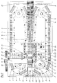
- a device for the production of plastic composite pipes with transverse grooves has a machine table 1 on which half molds 2 and 2 'are arranged, which are each connected to form so-called chains 3 and 3'.
- a tab 5 is articulated on each half mold 2 or 2 'in its outer area 4, which is at the front in the direction of production 4, by means of a pivot pin 6, which is also attached to the corresponding point of the subsequent half mold 2 or 2' by means of such a pivot bolt 6.
- the chains 3, 3 'formed in this way are guided at their rear end, seen in the direction of production 4, via deflection wheels serving as so-called infeed rollers 7.
- the individual half molds 2, 2 ' are pivoted into a mold section 9 in accordance with the direction of rotation arrows 8 and 8' during the rotation of the chains 3, 3 ', in which two half molds 2, 2' are combined to form a pair of molds, again in the production direction 4 successive pairs of molds lie close together.
- so-called closing rollers 10 are provided which accelerate the rear ends of the half molds 2, 2' in the production direction 4.
- a toothing 16 is formed, the two toothings 16 of the paired half molds 2, 2' being aligned with one another, so that a common drive pinion 17 can engage in this toothing 16 from above, which the half molds 2, 2 'in the mold section 9 as a closed mold pushes through the mold section 9.
- This drive pinion 17 is driven in the usual manner by a motor (not shown) via a drive gear 18 which is fixed in a rotationally fixed manner on a shaft 19 which in turn carries the drive pinion 17.
- the shaft 19 is mounted in a bearing block 20, which is supported via distance prisms 21 with respect to the machine table and is fixedly connected to the latter by means of screws 22.
- Plastic pipes 23 namely so-called composite pipes, with, among other things, a transverse profile, i.e. with circumferential grooves 24 produced.
- the tubes 23 are described in more detail below.
- an extruder is provided, of which only the spray head 25 to be described in more detail below is indicated.
- the device described so far is known, for example from EP-A o o65 729 (corresponding to US 4,492,551) and from DE 4o 21 564 A1.
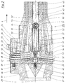
- the spray head 25 is fastened by means of screws 26 to a connecting part 27 of the extruder, not shown. It has an essentially annular nozzle body 28, to which all the essential parts of the spray head are attached. This nozzle body, concentric to a common central longitudinal axis 29 of the spray head 25, has an annular collar 3o projecting in the production direction 4. An inner nozzle mandrel 32 is fastened in this annular collar 3o by means of an internally threaded connection 31. An outer nozzle mandrel 34 is fastened on the outer circumference of the annular collar 3o by means of an external thread connection 33. Finally is again concentric to the axis 29, an outer nozzle jacket 35 is fastened to the nozzle body 28 by means of an adjusting ring 36 and by means of the screws 26.
- the inner nozzle mandrel 32 and the outer nozzle mandrel 34 delimit an inner channel 37 between them, while the outer nozzle mandrel 34 and the outer nozzle jacket 35 delimit an outer channel 38 between them.
- the inner channel 37 and the outer channel 38 are - as can be seen in FIG. 2 - connected to a spray channel 39 coming from the extruder.
- a guide cone 4o directed into the injection channel 39 against the production direction 4 is attached to the nozzle body 28.
- the inner channel 37 is penetrated by radially extending inner webs 41 and the outer channel 38 by outer webs 42, which also extend radially to the axis 29, so that the nozzle body 28 is actually a part.
- the inner channel 37 extends in the nozzle body 28 through the annular collar 30.
- the inner nozzle mandrel 32 is provided with a conduit channel 43 which runs concentrically to the axis 29 and opens into a chamber 44 in the nozzle body 28.
- a protective tube 45 is arranged concentrically to the axis 29, which is insulated from the inner nozzle mandrel 32 by an air gap 46.
- the protective tube 45 itself is made of steel.
- Supply hoses 47, 48, 49, 50, 51, 52, 53 are guided through the protective tube 45 in the line duct 43. These are guided radially from the outside through the nozzle body 28 into its chamber 44, for which purpose approximately radial bores 54 are formed in the nozzle body 28 and lead into the chamber 44, which of course penetrate the outer webs 42 and the inner webs 41 so that the hoses 47 to 53 do not come into contact with the melt transported in the channels 37 or 38.
- the hoses 47 to 53 are made of highly heat-resistant plastic, for example polytetrafluoroethylene.
- the outer nozzle jacket 35 is aligned and fixed by means of adjusting screws 55 which are mounted in the adjusting ring 36 and extend radially to the axis 29.
- Gas channels 56 are also formed in the outer nozzle mandrel 34, which extend in the production direction 4 and which are connected to a feed channel 57 in the nozzle body 28, which extends approximately radially to the axis 29 and passes through the webs 42.
- the spray head 2 is surrounded over a greater part of its length with heaters 58, 59 in order to avoid cooling of the melt coming from the spray channel 39 and guided through the channels 38.
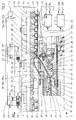
- the configuration of the spray head 25 in the region of its nozzles shown on the right in FIG. 2 is explained below with simultaneous reference to FIGS. 3 and 4.
- Arranged on the inner nozzle mandrel 32 is an inner mandrel plate 6o which widens in the shape of a truncated cone in the direction of production 4 and carries an inner mandrel designed as a tempering bell 62.
- This inner mandrel plate 6o delimits an inner nozzle 63 terminating the inner channel 37 on the side lying radially to the axis 29.
- An extension part 64 is attached to the outer nozzle mandrel 34 by means of a threaded connection 65, which connects the inner mandrel plate 6o in the direction of production 4 seen partially surrounds and thus surrounds an enlarged area of the inner channel 37 on the outside, namely in front of the inner nozzle 63. This is delimited on the radially outer side by means of an inner nozzle ring 66 which is arranged on the extension part 64 .
- the structure and the adjustment is described in more detail below.
- the inner mandrel plate 6o is arranged on a support tube 68 which runs concentrically to the axis 29 and is connected to the inner nozzle mandrel 32 by means of a threaded connection 61.
- the inner mandrel plate 6o is supported by means of a conical surface 69 on a corresponding conical seat surface 7o at the free end of the inner nozzle mandrel 32.
- the inner mandrel plate 6o can be adjusted slightly radially relative to the axis 29 on this conical seat surface 7o, as a result of which an adjustment shoulder 71 can be formed which is in any case smaller than 1 mm, generally not larger than 0.5 mm.
- an adjusting cone ring 72 is provided which, with a conical surface 73, bears against a conical seat surface 74 on the inside of the inner mandrel plate 6o. While the Tapered surface 69 and the tapered seat surface 7o taper when viewed in the direction of production 4, the tapered surface 73 and the associated tapered seat surface 74 expand in the direction of production 4.
- the adjusting cone ring 72 is guided with its cylindrical inner surface 75 on a spherical ring-shaped guide surface 76, the center 77 of which lies in the axis 29.
- Pressure adjusting screws 79 bear against a pressure surface 78 of the adjusting cone ring 72 facing away from the conical surface 73 and are adjustably guided in abutments 80, which in turn are firmly connected to the support tube 68.
- the adjusting cone ring 72 can be pivoted slightly on the spherical guide surface 76, so that the angle of inclination a of its conical surface 73 is not identical over the entire circumference of the adjusting cone ring 72.
- the inner mandrel plate 6o is adjusted eccentrically to the axis 29 on its support by means of the conical surface 69 on the conical seat surface 7o.
- the average inclination of the conical surface 73 to the axis 29 is 45 °; likewise, the inclination b of the conical seat surface 7o with respect to the axis 29 is approximately 45 °.
- the conical surface 69 and the conical seat surface 74 are thus inclined at 90 ° to one another.
- the width c of the inner nozzle 63 is set to a greater extent over its circumference. It can thus be set that the width c of the inner nozzle 63 is exactly the same over its circumference. On the other hand, it can also be used to set it to be unequal.
- the inner nozzle ring 66 is adjusted by means of an inner nozzle ring nut 81 in the direction of production 4 to adjust the width c of the inner nozzle 63.
- the inner nozzle ring nut 81 has an internal thread 82, which is supported on an external thread 83 of the extension part 64.
- the threads 82, 83 are concentric with the axis 29.
- the inner nozzle ring nut 81 has openings 84 which extend radially to the axis 29 and into which a tool can be used to rotate the nozzle ring nut 81.
- the inner nozzle ring nut 81 is connected to the inner nozzle ring 66 by means of a rotary connection 85 which cannot be displaced in the direction of the axis 29.
- the nozzle ring nut 81 has an undercut inner groove 86 on its side facing the inner nozzle ring 66.
- the inner nozzle ring 66 has an eccentric ring web 87, the central axis 88 of which is offset from the axis 29 by an eccentricity e.
- the inner nozzle ring 66 is shifted relative to the inner nozzle ring nut 81 by the eccentricity e and pushed into it, so that the eccentric annular web 87 comes into contact with the inner groove 86.
- This unit comprising the inner nozzle ring 66 and the inner nozzle ring nut 81 is then screwed onto the external thread 83.
- the inner nozzle ring 66 is guided with its cylindrical inner guide surface 89 on a likewise cylindrical outer guide surface 90 of the extension part 64.
- a high-temperature-resistant lubricant is located in the inner groove 86 for the greatest possible reduction of the frictional forces in the rotary connection 85. 5, 6 can be seen, the nozzle rings 66 and 91 can be made very short in the direction of production 4, and in fact significantly shorter than shown in FIGS. 3 and 4.
- an outer nozzle ring 91 is arranged so as to be adjustable in the direction of the axis 29 by means of an outer nozzle ring nut 92.
- the design is identical to that of the inner nozzle ring 66 with the inner nozzle ring nut 81, so that reference may be made to the previous description of the inner nozzle 63.
- the outer nozzle ring 91 delimits an outer nozzle 93 on the radially outer side, the width f of which can be changed in the direction of the axis 29 by the adjustment already described.
- the gas channels 56 open out of the spray head 25 between the outer nozzle 93 and the inner nozzle 63 arranged downstream in the production direction 4.
- the temperature control bell 62 has a generally cylindrical, essentially cylindrical calibration cylinder 94. This is arranged on a temperature control cylinder 95, which is provided on its outer circumference with a temperature control channel 96. This is supplied with temperature control medium via a temperature control flow channel 97, which is supplied via the supply hose 47 and is discharged via the supply hose 51.
- the temperature control duct 96 is usually designed as a heating duct, a cooling duct, which is not shown, then being arranged downstream of this in the production direction 4.
- Thermal insulation 98 is arranged between the temperature control bell 62 and the inner mandrel plate 60.
- the temperature control cylinder 95 is hollow and has in its interior a gas space 99 surrounding the support tube 68, which is connected to the supply hose 50.
- the gas space 99 is connected to the mold space 101 via a gas gap channel 100 which is formed in the separating surface between the inner mandrel plate 60 and the temperature control bell 62 and which is formed between the half molds 2 and 2 'and the spray head 25 with temperature control bell 62 .
- the gas gap channel 100 - seen in the direction of production 4 - opens directly into the mold space 101 behind the inner nozzle 63.
- annular shaped recesses 102 are formed which are connected to partial vacuum channels 103 in a known manner.
- the plastic melt supplied by the extruder through the injection channel 39 flows in part through the outer channel 38 to the outer nozzle 93 from which an outer hose 104 is extruded, which forms a tube provided with the transverse grooves 24 due to the partial vacuum into the mold recesses 102 sets. After appropriate cooling and solidification, it forms the corrugated outer tube 105 of the tube 23.
- the half molds 2, 2 ' are designed such that 23 pipe sleeves 108 are formed at predetermined intervals within the endlessly produced composite pipe.
- a substantially cylindrical sleeve recess 109 is formed in a pair of half molds 2, 2 ', which therefore has a smooth cylindrical wall 110.
- the partial vacuum channels 103 are not only connected to the shape recesses 102 by means of vacuum slots 111, as in the case of the shape recesses 102, but also by means of vacuum ring slots 112 the sleeve recess 109 connected so that partial vacuum is exerted on the outside of the outer hose 104 over the entire wall circumference.
- the details are shown in FIG. 7.
- a transition section 113 is formed between the socket recess 109 and the mold recess 102 'which leads in the production direction 4.
- the sleeve recess 109 can also extend over a plurality of half molds 2, 2 'arranged one behind the other.
- Form grooves 114 are formed at the rear end of the sleeve recess 109, as seen in production direction 4, in which inner grooves 115 for receiving a sealing ring 116 (FIG. 13) are formed in the pipe sleeve 108.
- a frustoconical shaped section 117 adjoins, in which an outwardly opening insert 118 of the sleeve is formed. This is in turn followed by a transition section 119, which leads to the next mold recess 102 - lagging in the production direction 4.
- a switching element 120 is formed by a rod-shaped extension of a pivot pin 6, which controls - in a manner still to be described - various valves to in the space between the outer hose 104 and inner hose 106 and / or 106 different pressure ratios within the inner tube to accomplish.
- a mounting bridge 121 is attached to the bearing block 20, which has a mounting arm 122 which extends in the production direction 4 above the half molds 2 '.
- Switches 123, 124 which can be actuated by the switching element 120 and by means of which solenoid valves 125, 125a can be actuated, are mounted on this mounting arm 122.
- switches 126, 127 mounted on the mounting arm 122 are actuated by means of the switching element 120, by means of which the drive motor (not shown) can be switched to different speeds.
- the switches 123, 124, 126, 127 are - as can be seen from FIGS. 3, 4, 8 - switched contactless, the contactless actuation of the switches 126, 127 being carried out by means of a switching cam 128.
- the switches 123, 124, 126, 127 are adjustably mounted on the mounting arm 122 in the direction of production 4, which is indicated by arrows 129.
- the switches 123, 124, 126, 127 are connected via lines 123a, 124a, 126a, 127a to a control device 125b which processes the signals coming from the switches 123, 124, 126, 127 and sends corresponding control signals to the solenoid valves 125, 125a .
- the solenoid valves 125, 125a are supplied with compressed air from a pressure source, not shown, with a pressure p which is higher than the outlet pressures of the solenoid valves 125, 125a to be explained below.
- the pressure in the gas gap channel 100 and thus within the inner hose 106 is controlled via the solenoid valve 125, while the pressure in the gas channels 56 and thus in the space between the outer hose 104 and the inner hose 106 is controlled by the solenoid valve 125a becomes.
- the solenoid valve 125 causes a pressure p1 of approximately 1.05 to 1.15 bar, that is to say a slight excess pressure of 0.05 to 0.15 bar , placed on the gas gap channel 100.
- a pressure p2 of approximately 1.2 to 1.3 bar that is also a lower but higher excess pressure of 0.2 to 0.3 bar, is applied to the gas channels 56.
- the slight overpressure inside the inner tube 106 prevents the inner tube 106 from sticking to the calibration cylinder 94 before it is welded to the outer tube 104.
- the switching element 120 arrives at the first switch 126, viewed in the direction of production 4, which switches the feed rate of the through the half molds 2, 2 'formed form reduced so that - with the same performance of the extruder - the inner nozzle 63 and the outer nozzle 93 more melt per unit length of the composite pipe 23 to be produced is supplied.
- the solenoid valve 125a is connected to the atmosphere, so that atmospheric pressure p3 prevails in the space between the outer hose 104 and the inner hose 106 and in particular the air can escape to the outside.
- the solenoid valve 125 is switched from p1 to a higher pressure p4 of approximately 1.2 to 1.45 bar, that is, to an overpressure of approximately 0.2 to 0.45 bar.
- the inner tube 106 is pressed outward against the outer tube 104. This is drawn anyway by the partial vacuum of approximately 0.7 to 0.3 bar in the vacuum ring slots 112 against the wall 110 of the sleeve recess 109.
- the overpressure pressed in by the gap 100 presses from the inside, so that the outer tube 104 and the inner tube 106 are welded to one another over the entire surface, so that they abut the wall 110 of the sleeve recess 109.
- the total wall thickness in the area of the pipe sleeve 108 is greater than in the corrugated area, so that the rigidity and compressive strength of the pipe sleeve 108 are the same as in the corrugated area.
- FIG. 10 shows a variant in which a spigot end is produced instead of a pipe socket, which therefore has a smaller outside diameter and is designed for insertion into a socket or another pipe connecting element.
- a tip end recess 131 is provided in the respective half mold 2 or 2 ', the diameter of which is only twice the wall thickness of the tip end 132 to be produced in comparison with the diameter of the calibration cylinder 94.
- the solenoid valve 125 is to be switched by the switch 123 in such a way that it is connected to the atmosphere.
- the solenoid valve 125a is simultaneously - as in the manufacture of the sleeve - switched so that it is open to the atmosphere, so that here too the air can be pressed outwards from the space between the outer hose 104 and the inner hose 106.
- the outer tube 104 and inner tube 106 are welded here only by pressing the two tubes together between the calibration cylinder 94 and the wall 133 of the tip-end recess 131.
- the speed of the shape is determined by correspondingly controlling the drive motor via the switch 126 has been withdrawn so that more melt per unit length of the pipe to be produced reaches the tip end 132, so that its wall thickness is greater than the sum of the wall thicknesses of outer pipe 105 and inner pipe 107.
- FIG. 11 shows how a composite pipe 23 is continuously produced in a pipe string, which has a spigot end 132 and - immediately following this - a pipe sleeve 108.
- the pipe piece 134 at the transition from the tip end 132 to the pipe sleeve 108 is cut out as waste by two saw cuts 135, 136.
- the tip end 132 has a slightly tapered insertion cone 137 at its free end.
- an additional switch for the continuous production of a composite pipe 23 with a pointed end 132 on the one hand and a pipe sleeve 108 on the other hand, an additional switch, not shown in the drawing, must be provided, through which the solenoid valves 125, 125a during the transition from the pointed end 132 to the pipe sleeve 108 change the printing conditions in the manner already described above.
- FIG. 12 shows a composite pipe 23 which on the one hand has a pipe sleeve 108 and which - before the transition to the corrugated composite pipe 23 again - has an additional double sleeve 138.
- This double sleeve 138 is cut out by saw cuts 139, 140 and is suitable as an accessory, that is to say for connecting two composite pipes that do not have a molded pipe sleeve 108.
- a piece of pipe 130 is naturally separated out as waste.
Priority Applications (1)
| Application Number | Priority Date | Filing Date | Title |
|---|---|---|---|
| DE9321573U DE9321573U1 (de) | 1992-03-31 | 1993-02-26 | Vorrichtung zur fortlaufenden Herstellung eines Verbundrohres mit Rohr-Muffe |
Applications Claiming Priority (2)
| Application Number | Priority Date | Filing Date | Title |
|---|---|---|---|
| DE4210482 | 1992-03-31 | ||
| DE4210482A DE4210482A1 (de) | 1992-03-31 | 1992-03-31 | Verfahren und Vorrichtung zur fortlaufenden Herstellung eines Verbundrohres mit Rohr-Muffe |
Publications (3)
| Publication Number | Publication Date |
|---|---|
| EP0563575A2 true EP0563575A2 (fr) | 1993-10-06 |
| EP0563575A3 EP0563575A3 (en) | 1993-12-29 |
| EP0563575B1 EP0563575B1 (fr) | 1995-09-27 |
Family
ID=6455480
Family Applications (1)
| Application Number | Title | Priority Date | Filing Date |
|---|---|---|---|
| EP93103013A Expired - Lifetime EP0563575B1 (fr) | 1992-03-31 | 1993-02-26 | Procédé et dispositif de production en continu d'un tube composite avec manchon |
Country Status (9)
| Country | Link |
|---|---|
| US (1) | US5320797B1 (fr) |
| EP (1) | EP0563575B1 (fr) |
| JP (1) | JP3319804B2 (fr) |
| CN (1) | CN1038919C (fr) |
| AT (1) | ATE128407T1 (fr) |
| CA (1) | CA2092641C (fr) |
| DE (2) | DE4210482A1 (fr) |
| ES (1) | ES2079907T3 (fr) |
| FI (1) | FI931416A (fr) |
Cited By (38)
| Publication number | Priority date | Publication date | Assignee | Title |
|---|---|---|---|---|
| DE19724113A1 (de) * | 1997-06-09 | 1998-12-10 | Ralph Peter Dr Hegler | Verbundrohr mit angeformter Rohr-Muffe und Verfahren zu dessen Herstellung |
| EP0913534A1 (fr) | 1997-10-30 | 1999-05-06 | Hegler, Ralph-Peter, Dr.-Ing. | Regard pour des canalisations de fluide et section de regard correspondant |
| EP0995579A3 (fr) * | 1998-10-21 | 2001-12-05 | Ralph-Peter Dr.-Ing. Hegler | Procédé de production en continu d'un tube composite avec manchon, et appareil pour la mise en oeuvre du procédé |
| DE10110064A1 (de) * | 2001-03-02 | 2002-09-12 | Lupke Manfred Arno Alfred | Verfahren und Vorrichtung zur Herstellung eines doppelwandigen thermoplastischen Rohres mit einer Rohrmuffe |
| WO2002070238A1 (fr) | 2001-03-02 | 2002-09-12 | Lupke Manfred Arno Alfred | Dispositif et procede de fabrication d'un tube thermoplastique a double paroi au moyen d'un manchon de tuyau |
| DE10225582A1 (de) * | 2002-06-10 | 2003-12-24 | Manfred Arno Alfred Lupke | Verfahren und Vorrichtung zur Herstellung eines doppelwandigen Rohres aus thermoplastischem Kunststoff mit einer Rohrmuffe |
| EP1475213A1 (fr) * | 2002-02-14 | 2004-11-10 | Denki Kagaku Kogyo Kabushiki Kaisha | Procede de production d'un tube ondule a double paroi |
| WO2005085696A1 (fr) | 2004-03-03 | 2005-09-15 | Ralph-Peter Hegler | Module tubulaire destine a une conduite tubulaire de canal et procede de fabrication |
| EP1612030A1 (fr) * | 2004-07-03 | 2006-01-04 | Ralph-Peter Dr.-Ing. Hegler | Procédé pour fabriquer en continu d'un tuyau ondulé à double parois avec manchon, le tuyau ondulé à double parois et le dispositif pour la mise en oeuvre |
| US7214051B2 (en) | 2003-07-31 | 2007-05-08 | Manfred A.A. Lupke | Device for manufacturing a double-walled thermoplastic pipe with a connecting sleeve |
| DE102006048512A1 (de) * | 2006-10-13 | 2008-04-17 | Hegler, Ralph Peter, Dr.-Ing. | Vorrichtung zur Herstellung von Verbund-Rohren |
| EP1935610A1 (fr) * | 2006-12-22 | 2008-06-25 | Drossbach GmbH & Co. KG | Procédé et dispositif de fabrication d'une pièce de formage en matière synthétique et pièce formée |
| EP2045068A2 (fr) | 2007-10-05 | 2009-04-08 | Ralph-Peter Dr.-Ing. Hegler | Procédé et dispositif de fabrication de tuyaux en plastique thermoplastique dotés d'un profilage transversal |
| EP2065159A1 (fr) | 2007-11-28 | 2009-06-03 | Ralph-Peter Dr.-Ing. Hegler | Dispositif de fabrication continue d'un tuyau composite doté d'un manchon tubulaire |
| EP2072988A1 (fr) | 2007-12-19 | 2009-06-24 | Ralph-Peter Dr.-Ing. Hegler | Procédé et dispositif de vérification |
| WO2009053009A3 (fr) * | 2007-10-23 | 2009-07-23 | Unicor Gmbh | Procédé et dispositif de fabrication d'un tube ondulé thermoplastique à double paroi, doté d'un manchon de raccord |
| CZ300788B6 (cs) * | 2001-02-09 | 2009-08-12 | Trubkový prvek | |
| WO2009103310A1 (fr) * | 2008-02-19 | 2009-08-27 | Ralph Peter Hegler | Procédé et dispositif de fabrication en continu d’un tube d’assemblage avec manchon de raccord, et tube d’assemblage |
| EP2103412A1 (fr) * | 2008-03-18 | 2009-09-23 | Ralph-Peter Dr.-Ing. Hegler | Procédé destiné à la fabrication continue d'un tuyau composite doté d'un manchon tubulaire et dispositif d'exécution du procédé |
| EP2116352A1 (fr) | 2008-05-09 | 2009-11-11 | Ralph-Peter Dr.-Ing. Hegler | Outil d'extrusion pour un dispositif pour la fabrication de tuyaux composites en matière synthétique avec des rainures obliques |
| FR2943940A1 (fr) * | 2009-04-07 | 2010-10-08 | Corelco Sas | Coquille pour la fabrication par depression de conduits anneles. |
| EP2286979A1 (fr) | 2009-08-22 | 2011-02-23 | Ralph Peter Hegler | Dispositif de fabrication de tubes ondulés de l'extérieur et dotés de manchons |
| EP2436504A2 (fr) | 2010-09-29 | 2012-04-04 | Ralph-Peter Dr.-Ing. Hegler | Procédé de fabrication continue d'un tuyau composite doté d'un manchon tubulaire, tuyau composite doté d'un manchon tubulaire et dispositif d'exécution du procédé et de fabrication du tuyau composite |
| EP2620683A1 (fr) | 2012-01-24 | 2013-07-31 | Ralph Peter Hegler | Tuyau composite pour la technique de climatisation et d'aération |
| DE10164897B4 (de) * | 2001-03-02 | 2015-02-12 | Manfred Arno Alfred Lupke | Verfahren und Vorrichtung zur Herstellung eines doppelwandigen thermoplastischen Rohres mit einer Rohrmuffe |
| EP2930411A1 (fr) | 2014-04-10 | 2015-10-14 | Ralph Peter Hegler | Élément de liaison de tubes |
| EP2960387A1 (fr) | 2014-06-27 | 2015-12-30 | Ralph Peter Hegler | Kit de liaison de tuyau |
| DE102014218372A1 (de) | 2014-09-12 | 2016-03-17 | Ralph Peter Hegler | Inspektions- bzw. Revisions-Schacht aus Kunststoff |
| DE102010051181B4 (de) * | 2010-11-15 | 2016-09-08 | Unicor Gmbh | Korrugatoreinrichtung |
| EP3130709A1 (fr) | 2015-08-11 | 2017-02-15 | Ralph-Peter Dr.-Ing. Hegler | Corps de base de cage en plastique pour une cage de revision ou d'inspection |
| DE102015226513A1 (de) | 2015-12-22 | 2017-06-22 | Ralph Peter Hegler | Bausatz für eine Rohrverbindung und Dichtungs-Ring für eine solche Rohrverbindung |
| DE10165124B3 (de) | 2001-03-02 | 2018-05-30 | Manfred Arno Alfred Lupke | Verfahren und Vorrichtung zur Herstellung eines doppelwandigen thermoplastischen Rohres mit einer Rohrmuffe |
| WO2018162441A1 (fr) * | 2017-03-10 | 2018-09-13 | Uniwell Rohrsysteme Gmbh & Co. Kg | Tuyau à pression et procédé de fabrication d'un tuyau à pression |
| US10583596B2 (en) | 2015-10-06 | 2020-03-10 | Ralph Peter Hegler | Injection head for an apparatus for the production of a twin-wall pipe |
| EP3667144A1 (fr) | 2018-12-12 | 2020-06-17 | Ralph Peter Hegler | Ensemble pour établir un raccord entre deux tubes composite pour la climatisation et la ventilation. |
| EP3667143A1 (fr) | 2018-12-12 | 2020-06-17 | Ralph Peter Hegler | Tube de raccordement pour la technique de climatisation et d'aération |
| DE102020206402A1 (de) | 2020-05-22 | 2021-11-25 | Hegler Plastik Gmbh | Bausatz für einen Inspektions-Schacht und Dichtung für einen solchen Bausatz |
| DE102020212344A1 (de) | 2020-09-30 | 2022-03-31 | Ralph Peter Hegler | Bausatz für eine Wasser-Transport-Leitung |
Families Citing this family (36)
| Publication number | Priority date | Publication date | Assignee | Title |
|---|---|---|---|---|
| CA2072663C (fr) * | 1992-06-29 | 1999-11-16 | Manfred A. A. Lupke | Methode et machine pour former des tubes thermoplastiques a double paroi et tulipes integrees |
| DE4240268A1 (de) * | 1992-12-01 | 1994-06-09 | Wilhelm Hegler | Verfahren und Vorrichtung zur fortlaufenden Herstellung eines Verbundrohres mit einem außen im wesentlichen glatten Abschnitt |
| ES2149209T3 (es) * | 1993-06-30 | 2000-11-01 | Manfred Arno Alfred Lupke | Metodo y aparato para formar un tubo termoplastico de doble pared con campanas integradas. |
| US5513975A (en) * | 1994-04-07 | 1996-05-07 | Advanced Drainage Systems, Inc. | Pipe extrusion die head manifold assembly |
| US5513974A (en) * | 1994-04-07 | 1996-05-07 | Advanced Drainage Systems, Inc. | Manifold assembly with atmospheric vent |
| US5542834A (en) * | 1994-11-10 | 1996-08-06 | Lupke; Manfred A. A. | Skinned double wall pipe and apparatus for making same |
| DE19504501A1 (de) * | 1995-02-13 | 1996-08-14 | Wilhelm Hegler | Verfahren und Anlage zur Herstellung eines Mehrschicht-Rohres aus thermoplastischem Kunststoff, insbesondere Polyolefin |
| DE19535231A1 (de) * | 1995-09-22 | 1997-03-27 | Hegler Ralph Peter | Vorrichtung zur Herstellung von Rohren aus thermoplastischem Kunststoff mit Querprofilierung |
| DE19604311A1 (de) * | 1996-02-07 | 1997-08-14 | Ralph Peter Dr Ing Hegler | Verbundrohr mit Muffe und Verfahren zu seiner Herstellung |
| DE19640928A1 (de) * | 1996-10-04 | 1998-04-09 | Ralph Peter Dr Ing Hegler | Vorrichtung zur Herstellung von Kunststoff-Verbund-Rohren |
| US6386551B1 (en) * | 1997-03-05 | 2002-05-14 | Trw Inc. | Plastic sleeve and method of manufacturing the same |
| CA2231624C (fr) * | 1998-03-09 | 2001-02-06 | Manfred A. A. Lupke | Appareil de moulage de tuyau avec coussin d'air pour faire flotter le mur de plastique interne par-dessus la soupape conique de refroidissement |
| US6199592B1 (en) * | 1999-02-05 | 2001-03-13 | Hancor, Inc. | Pipe structure and method of manufacture |
| US6764627B2 (en) * | 2000-03-23 | 2004-07-20 | Hahn Elastomer Corporation | Method of making corrugated part |
| US6682689B1 (en) | 2000-05-03 | 2004-01-27 | Jpmorgan Chase Bank | Flexible plastic article and method of manufacturing the same |
| EP1379377B1 (fr) | 2000-09-11 | 2011-02-02 | Manfred Arno Alfred Lupke | Appareil de moulage dote d'un tunnel de moulage a mouvement alternatif et capable de produire differentes formes d'articles |
| DE10058890C1 (de) * | 2000-11-24 | 2002-05-02 | Binder Gottlieb Gmbh & Co | Verfahren zum fortlaufenden Herstellen von Haftverschlußteilen |
| DE10058889A1 (de) * | 2000-11-24 | 2002-06-06 | Binder Gottlieb Gmbh & Co | Verfahren zum Herstellen von Profilen |
| DE10117126C1 (de) * | 2001-04-06 | 2002-08-01 | Unicor Rohrsysteme Gmbh | Vorrichtung zur Herstellung von Doppelwand-Wellrohren |
| DE10328626A1 (de) * | 2003-06-26 | 2005-01-13 | Hegler, Ralph-Peter, Dr.-Ing. | Rohr-Bausatz |
| DE102004002574A1 (de) | 2004-01-17 | 2005-08-04 | Hegler, Ralph-Peter, Dr.-Ing. | Rohr-Bausatz für Kanal-Rohrleitung |
| DE102004020929A1 (de) * | 2004-04-28 | 2005-11-24 | Hegler, Ralph-Peter, Dr.-Ing. | Bausatz für eine Rohr-Verbindung und dessen Verwendung |
| DE102005029580B3 (de) * | 2005-06-25 | 2006-10-26 | Unicor Gmbh | Vorrichtung zur Herstellung von doppelwandigen Verbundrohren |
| EP1957250B1 (fr) * | 2005-11-16 | 2018-05-23 | Manufacturing Systems Limited | Ameliorations apportees ou se rapportant a un dispositif de formage |
| DE202007002954U1 (de) * | 2007-03-01 | 2007-04-26 | Hegler, Ralph Peter, Dr.-Ing. | Vorrichtung zur fortlaufenden Herstellung eines Verbundrohres mit Rohrmuffe |
| DE202008018223U1 (de) | 2008-03-18 | 2012-02-13 | Ralph Peter Hegler | Vorrichtung zur fortlaufenden Herstellung einesVerbundrohres mit Rohrmuffe |
| DE102008027102B4 (de) | 2008-06-06 | 2011-11-17 | Unicor Gmbh | Doppelwand-Wellrohr und Formbacken für eine Vorrichtung zur Herstellung eines derartigen Doppelwand-Wellrohres |
| KR101805000B1 (ko) | 2008-10-07 | 2017-12-07 | 메뉴팩터링 시스템즈 리미티드 | 형성 방법 |
| DE102009013066A1 (de) | 2009-03-16 | 2010-09-23 | Hegler, Ralph Peter, Dr.-Ing. | Bausatz für eine Verbindung eines Inspektions-Schachtes mit einer Abfluss-Leitung |
| DE102009035040B4 (de) | 2009-07-28 | 2011-12-15 | Ralph Peter Hegler | Verfahren zur fortlaufenden Herstellung eines Rohres und Vorrichtung zur Durchführung des Verfahrens |
| DE102009037042A1 (de) | 2009-08-13 | 2011-02-17 | Hegler Plastik Gmbh | Schacht, insbesondere Kontroll- und Spül-Schacht für Abwasser mit einem Fließ-Gerinne und Platte für ein Fließ-Gerinne |
| DE102010043786B4 (de) | 2010-11-11 | 2013-07-18 | Ralph Peter Hegler | Vorrichtung zur Herstellung von Rohren aus thermoplastischem Kunststoff |
| PL2589481T3 (pl) | 2011-11-04 | 2016-06-30 | Ralph Peter Hegler | Urządzenie do ciągłego wytwarzania rury wielowarstwowej z kielichem łączącym |
| DE102013007530A1 (de) | 2013-05-03 | 2014-11-06 | Unicor Gmbh | Herstellung eines doppellagigen Wellrohres mit Rohrmuffe |
| CA2857699C (fr) * | 2014-07-23 | 2020-07-28 | Manfred A. A. Lupke | Amelioration de la regulation de la pression d'air d'une onduleuse |
| CN105690717B (zh) * | 2016-01-29 | 2018-02-06 | 姜维雁 | 密封保温管的制造系统及制造方法 |
Citations (6)
| Publication number | Priority date | Publication date | Assignee | Title |
|---|---|---|---|---|
| DE2403618A1 (de) * | 1974-01-25 | 1975-08-07 | Fraenk Isolierrohr & Metall | Vorrichtung zum herstellen eines doppelwandigen kunststoffrohres |
| FR2264649A1 (fr) * | 1974-03-22 | 1975-10-17 | Hegler Wilhelm | |
| WO1985002144A1 (fr) * | 1983-11-15 | 1985-05-23 | Uponor Ab | Tuyau a paroi unique a base de plastique ou d'autres materiaux moulables, procede et appareil pour l'extrusion continue de tels tuyaux |
| WO1988005377A1 (fr) * | 1987-01-22 | 1988-07-28 | Uponor N.V. | Procede et dispositif pour l'extrusion de tubes en plastique |
| US4846660A (en) * | 1984-07-18 | 1989-07-11 | Contech Construction Products Inc. | Apparatus for producing double wall pipe |
| WO1990014208A1 (fr) * | 1989-05-17 | 1990-11-29 | Lupke Manfred Arno Alfred | Procede de formage de tubes par l'application d'aspiration et de pression pneumatique a la surface du mandrin de refroidissement |
Family Cites Families (18)
| Publication number | Priority date | Publication date | Assignee | Title |
|---|---|---|---|---|
| US3743456A (en) * | 1971-08-20 | 1973-07-03 | Acme Hamilton Mfg Corp | Adjustable die heads for extruders and the like |
| FR2153216A1 (en) * | 1971-09-22 | 1973-05-04 | Courant Emile | Ribbed plastic tube prodn - by extrusion into mobile mould halves |
| FR69963E (fr) * | 1974-03-22 | 1959-01-30 | Onera (Off Nat Aerospatiale) | Appareil pour le dépouillement d'enregistrements |
| DE2637995C2 (de) * | 1976-08-24 | 1983-05-26 | Hegler, Wilhelm, 8730 Bad Kissingen | Verfahren zur Herstellung von doppelwandigen Kunststoffrohren mit einer ringförmig gewellten Außenwand und einer glatten Innenwand |
| DE3032891A1 (de) * | 1980-09-01 | 1982-04-15 | Henkel KGaA, 4000 Düsseldorf | Verfahren zur reduzierung der konzentration von loesungsmitteldampf |
| DE3120480A1 (de) * | 1981-05-22 | 1982-12-09 | Hegler, Wilhelm, 8730 Bad Kissingen | Vorrichtung zur herstellung von kunststoffrohren mit querrillen |
| CA1172813A (fr) * | 1982-06-16 | 1984-08-21 | Lupke, Manfred A. A. | Dispositif pour la production de tubes multiparoi en matiere thermoplastique |
| CA1187258A (fr) * | 1982-12-02 | 1985-05-21 | Lupke, Manfred A. A. | Methode et dispositif de fabrication de tubes thermoplastiques a double paroi et emboitement |
| US4500284A (en) * | 1983-09-16 | 1985-02-19 | Lupke Manfred Arno Alfred | Forming single wall bells in double wall pipe |
| JPS60124240A (ja) * | 1983-12-08 | 1985-07-03 | Takiron Co Ltd | 二重壁管の製造装置 |
| US5124109A (en) * | 1984-07-18 | 1992-06-23 | Contech Construction Products Inc. | Method for producing a double wall pipe |
| US4770618A (en) * | 1986-01-15 | 1988-09-13 | Lupke Manfred Arno Alfred | Extrusion die for two-ply plastic tubing |
| US4936768A (en) * | 1986-03-25 | 1990-06-26 | Lupke Manfred Arno Alfred | Extrusion die for externally ribbed plastic tubing |
| JPH066329B2 (ja) * | 1987-02-05 | 1994-01-26 | ウポノール・エヌ・ベー | プラスチツク管の押出しのための方法及び装置 |
| US5186878A (en) * | 1989-01-16 | 1993-02-16 | Corma Inc. | Improvements relating to cooling plugs in thermoplastic pipe forming apparatus and process |
| DK0385465T4 (da) * | 1989-03-03 | 1999-12-13 | Pipelife Rohrsysteme Gmbh | Fremgangsmåde til fremstilling af et kloakrør af plast |
| CA1319478C (fr) * | 1989-09-28 | 1993-06-29 | Manfred A. A. Lupke | Filiere a buse d'extrusion allongee pour faciliter le changement d'outils |
| DE4021564A1 (de) * | 1990-07-06 | 1992-01-09 | Wilhelm Hegler | Vorrichtung zur herstellung von kunststoff-rohren |
-
1992
- 1992-03-31 DE DE4210482A patent/DE4210482A1/de not_active Withdrawn
-
1993
- 1993-02-26 AT AT93103013T patent/ATE128407T1/de not_active IP Right Cessation
- 1993-02-26 EP EP93103013A patent/EP0563575B1/fr not_active Expired - Lifetime
- 1993-02-26 DE DE59300648T patent/DE59300648C5/de not_active Expired - Lifetime
- 1993-02-26 ES ES93103013T patent/ES2079907T3/es not_active Expired - Lifetime
- 1993-03-09 US US08028394 patent/US5320797B1/en not_active Expired - Lifetime
- 1993-03-12 CA CA002092641A patent/CA2092641C/fr not_active Expired - Lifetime
- 1993-03-25 CN CN93103594A patent/CN1038919C/zh not_active Expired - Fee Related
- 1993-03-29 FI FI931416A patent/FI931416A/fi not_active Application Discontinuation
- 1993-03-30 JP JP07187793A patent/JP3319804B2/ja not_active Expired - Lifetime
Patent Citations (6)
| Publication number | Priority date | Publication date | Assignee | Title |
|---|---|---|---|---|
| DE2403618A1 (de) * | 1974-01-25 | 1975-08-07 | Fraenk Isolierrohr & Metall | Vorrichtung zum herstellen eines doppelwandigen kunststoffrohres |
| FR2264649A1 (fr) * | 1974-03-22 | 1975-10-17 | Hegler Wilhelm | |
| WO1985002144A1 (fr) * | 1983-11-15 | 1985-05-23 | Uponor Ab | Tuyau a paroi unique a base de plastique ou d'autres materiaux moulables, procede et appareil pour l'extrusion continue de tels tuyaux |
| US4846660A (en) * | 1984-07-18 | 1989-07-11 | Contech Construction Products Inc. | Apparatus for producing double wall pipe |
| WO1988005377A1 (fr) * | 1987-01-22 | 1988-07-28 | Uponor N.V. | Procede et dispositif pour l'extrusion de tubes en plastique |
| WO1990014208A1 (fr) * | 1989-05-17 | 1990-11-29 | Lupke Manfred Arno Alfred | Procede de formage de tubes par l'application d'aspiration et de pression pneumatique a la surface du mandrin de refroidissement |
Cited By (63)
| Publication number | Priority date | Publication date | Assignee | Title |
|---|---|---|---|---|
| EP0890770A3 (fr) * | 1997-06-09 | 2000-01-12 | Hegler, Ralph-Peter, Dr.-Ing. | Tube composite avec manchon intégrée et méthode pour sa fabrication |
| DE19724113A1 (de) * | 1997-06-09 | 1998-12-10 | Ralph Peter Dr Hegler | Verbundrohr mit angeformter Rohr-Muffe und Verfahren zu dessen Herstellung |
| EP0913534A1 (fr) | 1997-10-30 | 1999-05-06 | Hegler, Ralph-Peter, Dr.-Ing. | Regard pour des canalisations de fluide et section de regard correspondant |
| CN1107586C (zh) * | 1998-10-21 | 2003-05-07 | 拉尔夫·P·赫格勒 | 连续制造具有承口的双壁管的方法及实施该方法的设备 |
| EP0995579A3 (fr) * | 1998-10-21 | 2001-12-05 | Ralph-Peter Dr.-Ing. Hegler | Procédé de production en continu d'un tube composite avec manchon, et appareil pour la mise en oeuvre du procédé |
| CZ300788B6 (cs) * | 2001-02-09 | 2009-08-12 | Trubkový prvek | |
| US7625196B2 (en) | 2001-03-02 | 2009-12-01 | Lupke Manfred A A | Device for manufacturing a double-walled, thermoplastic tube with a connecting sleeve |
| WO2002070238A1 (fr) | 2001-03-02 | 2002-09-12 | Lupke Manfred Arno Alfred | Dispositif et procede de fabrication d'un tube thermoplastique a double paroi au moyen d'un manchon de tuyau |
| DE10164897B4 (de) * | 2001-03-02 | 2015-02-12 | Manfred Arno Alfred Lupke | Verfahren und Vorrichtung zur Herstellung eines doppelwandigen thermoplastischen Rohres mit einer Rohrmuffe |
| DE10110064B4 (de) * | 2001-03-02 | 2005-03-31 | Lupke, Manfred Arno Alfred, Thornhill | Verfahren und Vorrichtung zur Herstellung eines doppelwandigen thermoplastischen Rohres mit einer Rohrmuffe |
| DE10110064A1 (de) * | 2001-03-02 | 2002-09-12 | Lupke Manfred Arno Alfred | Verfahren und Vorrichtung zur Herstellung eines doppelwandigen thermoplastischen Rohres mit einer Rohrmuffe |
| DE10165124B3 (de) | 2001-03-02 | 2018-05-30 | Manfred Arno Alfred Lupke | Verfahren und Vorrichtung zur Herstellung eines doppelwandigen thermoplastischen Rohres mit einer Rohrmuffe |
| US7691317B2 (en) | 2001-03-02 | 2010-04-06 | Corma, Inc. | Method and device for manufacturing a double-walled, thermoplastic tube with a connecting sleeve |
| EP1363766B2 (fr) † | 2001-03-02 | 2014-02-12 | Manfred Arno Alfred Lupke | Dispositif et procede de fabrication d'un tube thermoplastique a double paroi au moyen d'un manchon de tuyau |
| EP1475213A4 (fr) * | 2002-02-14 | 2007-12-05 | Denki Kagaku Kogyo Kk | Procede de production d'un tube ondule a double paroi |
| EP1475213A1 (fr) * | 2002-02-14 | 2004-11-10 | Denki Kagaku Kogyo Kabushiki Kaisha | Procede de production d'un tube ondule a double paroi |
| DE10225582A1 (de) * | 2002-06-10 | 2003-12-24 | Manfred Arno Alfred Lupke | Verfahren und Vorrichtung zur Herstellung eines doppelwandigen Rohres aus thermoplastischem Kunststoff mit einer Rohrmuffe |
| DE10225582B4 (de) * | 2002-06-10 | 2016-10-27 | Manfred Arno Alfred Lupke | Verfahren und Vorrichtung zur Herstellung eines doppelwandigen Rohres aus thermoplastischem Kunststoff mit einer Rohrmuffe |
| US7214051B2 (en) | 2003-07-31 | 2007-05-08 | Manfred A.A. Lupke | Device for manufacturing a double-walled thermoplastic pipe with a connecting sleeve |
| WO2005085696A1 (fr) | 2004-03-03 | 2005-09-15 | Ralph-Peter Hegler | Module tubulaire destine a une conduite tubulaire de canal et procede de fabrication |
| WO2006002743A1 (fr) * | 2004-07-03 | 2006-01-12 | Ralph-Peter Hegler | Procede pour fabriquer en continu un tube d'assemblage avec manchon de raccord, tube d'assemblage et dispositif pour realiser ce procede et fabriquer ce tube d'assemblage |
| AU2005259613B2 (en) * | 2004-07-03 | 2009-07-02 | Ralph-Peter Hegler | Method of continuously producing a twin-wall pipe with a socket, twin-wall pipe and apparatus for implementing the method and for producing the twin-wall pipe |
| EP1612030A1 (fr) * | 2004-07-03 | 2006-01-04 | Ralph-Peter Dr.-Ing. Hegler | Procédé pour fabriquer en continu d'un tuyau ondulé à double parois avec manchon, le tuyau ondulé à double parois et le dispositif pour la mise en oeuvre |
| DE102006048512B4 (de) * | 2006-10-13 | 2014-03-06 | Ralph Peter Hegler | Vorrichtung zur Herstellung von Verbund-Rohren |
| DE102006048512A1 (de) * | 2006-10-13 | 2008-04-17 | Hegler, Ralph Peter, Dr.-Ing. | Vorrichtung zur Herstellung von Verbund-Rohren |
| EP1935610A1 (fr) * | 2006-12-22 | 2008-06-25 | Drossbach GmbH & Co. KG | Procédé et dispositif de fabrication d'une pièce de formage en matière synthétique et pièce formée |
| DE102007047662A1 (de) | 2007-10-05 | 2009-04-09 | Hegler, Ralph-Peter, Dr.-Ing. | Verfahren und Vorrichtung zur Herstellung von Rohren aus thermoplastischem Kunststoff mit Querprofilierung |
| EP2045068A2 (fr) | 2007-10-05 | 2009-04-08 | Ralph-Peter Dr.-Ing. Hegler | Procédé et dispositif de fabrication de tuyaux en plastique thermoplastique dotés d'un profilage transversal |
| EP2574444A3 (fr) * | 2007-10-23 | 2014-01-01 | UNICOR GmbH | Procédé et dispositif de fabrication d'un tube ondulé thermoplastique à double paroi avec un manchon tubulaire |
| RU2472620C2 (ru) * | 2007-10-23 | 2013-01-20 | Уникор Гмбх | Способ для производства термопластичной гофрированной трубы с двойными стенками, имеющей соединительную муфту |
| US8231824B2 (en) | 2007-10-23 | 2012-07-31 | Unicor Gmbh | Method and device for producing a double-walled thermoplastic corrugated pipe having a connecting sleeve |
| WO2009053009A3 (fr) * | 2007-10-23 | 2009-07-23 | Unicor Gmbh | Procédé et dispositif de fabrication d'un tube ondulé thermoplastique à double paroi, doté d'un manchon de raccord |
| EP2065159A1 (fr) | 2007-11-28 | 2009-06-03 | Ralph-Peter Dr.-Ing. Hegler | Dispositif de fabrication continue d'un tuyau composite doté d'un manchon tubulaire |
| EP2072988A1 (fr) | 2007-12-19 | 2009-06-24 | Ralph-Peter Dr.-Ing. Hegler | Procédé et dispositif de vérification |
| US8783299B2 (en) | 2008-02-19 | 2014-07-22 | Ralph Peter Hegler | Method of and apparatus for continuously producing a twin-wall pipe comprising pipe socket and twin-wall pipe |
| WO2009103310A1 (fr) * | 2008-02-19 | 2009-08-27 | Ralph Peter Hegler | Procédé et dispositif de fabrication en continu d’un tube d’assemblage avec manchon de raccord, et tube d’assemblage |
| EP2103412A1 (fr) * | 2008-03-18 | 2009-09-23 | Ralph-Peter Dr.-Ing. Hegler | Procédé destiné à la fabrication continue d'un tuyau composite doté d'un manchon tubulaire et dispositif d'exécution du procédé |
| EP2116352A1 (fr) | 2008-05-09 | 2009-11-11 | Ralph-Peter Dr.-Ing. Hegler | Outil d'extrusion pour un dispositif pour la fabrication de tuyaux composites en matière synthétique avec des rainures obliques |
| EP2239126A1 (fr) * | 2009-04-07 | 2010-10-13 | Corelco SAS | Coquille pour la fabrication par dépression de conduits annelés, conduit annelé et le procédé |
| FR2943940A1 (fr) * | 2009-04-07 | 2010-10-08 | Corelco Sas | Coquille pour la fabrication par depression de conduits anneles. |
| DE102009038547A1 (de) | 2009-08-22 | 2011-02-24 | Hegler, Ralph Peter, Dr.-Ing. | Vorrichtung zur Herstellung von außen gewellten Rohren mit Muffen |
| EP2286979A1 (fr) | 2009-08-22 | 2011-02-23 | Ralph Peter Hegler | Dispositif de fabrication de tubes ondulés de l'extérieur et dotés de manchons |
| EP2436504A3 (fr) * | 2010-09-29 | 2014-07-09 | Ralph-Peter Dr.-Ing. Hegler | Procédé de fabrication continue d'un tuyau composite doté d'un manchon tubulaire, tuyau composite doté d'un manchon tubulaire et dispositif d'exécution du procédé et de fabrication du tuyau composite |
| EP2436504A2 (fr) | 2010-09-29 | 2012-04-04 | Ralph-Peter Dr.-Ing. Hegler | Procédé de fabrication continue d'un tuyau composite doté d'un manchon tubulaire, tuyau composite doté d'un manchon tubulaire et dispositif d'exécution du procédé et de fabrication du tuyau composite |
| DE102010051181B4 (de) * | 2010-11-15 | 2016-09-08 | Unicor Gmbh | Korrugatoreinrichtung |
| EP2620683A1 (fr) | 2012-01-24 | 2013-07-31 | Ralph Peter Hegler | Tuyau composite pour la technique de climatisation et d'aération |
| EP2930411A1 (fr) | 2014-04-10 | 2015-10-14 | Ralph Peter Hegler | Élément de liaison de tubes |
| EP2960387A1 (fr) | 2014-06-27 | 2015-12-30 | Ralph Peter Hegler | Kit de liaison de tuyau |
| DE102014218372A1 (de) | 2014-09-12 | 2016-03-17 | Ralph Peter Hegler | Inspektions- bzw. Revisions-Schacht aus Kunststoff |
| EP3130709A1 (fr) | 2015-08-11 | 2017-02-15 | Ralph-Peter Dr.-Ing. Hegler | Corps de base de cage en plastique pour une cage de revision ou d'inspection |
| DE102015215255A1 (de) | 2015-08-11 | 2017-02-16 | Ralph Peter Hegler | Schacht-Grundkörper aus Kunststoff für einen Inspektions- beziehungsweise Revisions-Schacht |
| US10583596B2 (en) | 2015-10-06 | 2020-03-10 | Ralph Peter Hegler | Injection head for an apparatus for the production of a twin-wall pipe |
| DE102015226513A1 (de) | 2015-12-22 | 2017-06-22 | Ralph Peter Hegler | Bausatz für eine Rohrverbindung und Dichtungs-Ring für eine solche Rohrverbindung |
| DE102015226513B4 (de) | 2015-12-22 | 2019-02-21 | Ralph Peter Hegler | Bausatz für eine Rohrverbindung und Dichtungs-Ring für eine solche Rohrverbindung |
| EA039277B1 (ru) * | 2017-03-10 | 2021-12-27 | Юнивелл Рорзистеме Гмбх Унд Ко. Кг | Напорный шланг и способ изготовления напорного шланга |
| WO2018162441A1 (fr) * | 2017-03-10 | 2018-09-13 | Uniwell Rohrsysteme Gmbh & Co. Kg | Tuyau à pression et procédé de fabrication d'un tuyau à pression |
| US11933439B2 (en) | 2017-03-10 | 2024-03-19 | Uniwell Rohrsysteme Gmbh & Co. Kg | Pressure hose and method for producing a pressure hose |
| EP3667144A1 (fr) | 2018-12-12 | 2020-06-17 | Ralph Peter Hegler | Ensemble pour établir un raccord entre deux tubes composite pour la climatisation et la ventilation. |
| DE102018221508A1 (de) | 2018-12-12 | 2020-06-18 | Ralph Peter Hegler | Verbundrohr für Klima- und Lüftungstechnik |
| DE102018221506A1 (de) | 2018-12-12 | 2020-06-18 | Ralph Peter Hegler | Bausatz zur Herstellung einer Verbindung zwischen zwei Verbundrohren für Klima- und Lüftungstechnik |
| EP3667143A1 (fr) | 2018-12-12 | 2020-06-17 | Ralph Peter Hegler | Tube de raccordement pour la technique de climatisation et d'aération |
| DE102020206402A1 (de) | 2020-05-22 | 2021-11-25 | Hegler Plastik Gmbh | Bausatz für einen Inspektions-Schacht und Dichtung für einen solchen Bausatz |
| DE102020212344A1 (de) | 2020-09-30 | 2022-03-31 | Ralph Peter Hegler | Bausatz für eine Wasser-Transport-Leitung |
Also Published As
| Publication number | Publication date |
|---|---|
| US5320797A (en) | 1994-06-14 |
| DE4210482A1 (de) | 1993-10-07 |
| FI931416A0 (fi) | 1993-03-29 |
| EP0563575B1 (fr) | 1995-09-27 |
| DE59300648C5 (de) | 2010-07-08 |
| ATE128407T1 (de) | 1995-10-15 |
| CN1077160A (zh) | 1993-10-13 |
| CN1038919C (zh) | 1998-07-01 |
| JPH0615713A (ja) | 1994-01-25 |
| CA2092641C (fr) | 1995-05-16 |
| FI931416A (fi) | 1993-10-01 |
| US5320797B1 (en) | 1997-04-08 |
| DE59300648D1 (de) | 1995-11-02 |
| JP3319804B2 (ja) | 2002-09-03 |
| ES2079907T3 (es) | 1996-01-16 |
| EP0563575A3 (en) | 1993-12-29 |
Similar Documents
| Publication | Publication Date | Title |
|---|---|---|
| EP0563575B1 (fr) | Procédé et dispositif de production en continu d'un tube composite avec manchon | |
| EP0890770B1 (fr) | Tube composite avec manchon intégrée et méthode pour sa fabrication | |
| EP0789176B1 (fr) | Tube composite avec manchon et procédé pour sa fabrication | |
| EP1115550B1 (fr) | Dispositif pour la production de tubes en matiere plastique | |
| EP0301189B1 (fr) | Procédé et dispositif de fabrication d'un tube nervuré en matière plastique | |
| EP0995579B1 (fr) | Procédé de production en continu d'un tube composite avec manchon, et appareil pour la mise en oeuvre du procédé | |
| EP0600214B2 (fr) | Procédé et dispositif pour la fabrication continue d'un tube composite comprenant une partie extérieuere essentiellement lisse | |
| EP2589481A1 (fr) | Dispositif de fabrication continue d'un tuyau composite doté d'un manchon de raccordement | |
| DE19835189A1 (de) | Vorrichtung zur kontinuierlichen Herstellung von nahtlosen Kunststoffrohren | |
| EP1612030A1 (fr) | Procédé pour fabriquer en continu d'un tuyau ondulé à double parois avec manchon, le tuyau ondulé à double parois et le dispositif pour la mise en oeuvre | |
| EP2065159A1 (fr) | Dispositif de fabrication continue d'un tuyau composite doté d'un manchon tubulaire | |
| EP2452803B1 (fr) | Dispositif pour la fabrication des tubes thermoplastiques ondulées | |
| EP0465889A2 (fr) | Dispositif pour la fabrication de corps creux en matière thermoplastique | |
| DE19640928A1 (de) | Vorrichtung zur Herstellung von Kunststoff-Verbund-Rohren | |
| EP2125329B1 (fr) | Procédé et dispositif de fabrication en continu d'un tube d'assemblage en matière plastique avec manchon de raccord | |
| DE102007026309B3 (de) | Vorrichtung zum Herstellen von runden oder ovalen Kunststoffrohren | |
| DE102006049660B3 (de) | Vorrichtung zum Extrudieren von Hohlsträngen | |
| DE4111229A1 (de) | Vorrichtung zur herstellung von kunststoff-rohren | |
| DE2821559C2 (fr) | ||
| WO2000016960A1 (fr) | Dispositif pour la production de tubes en matiere plastique | |
| DE2907802A1 (de) | Spritzkopfanordnung | |
| EP2574444B1 (fr) | Procédé et dispositif de fabrication d'un tube ondulé thermoplastique à double paroi avec un manchon tubulaire | |
| EP0243516A1 (fr) | Dispositif pour l'extrusion d'un tube en matière plastique à double paroi | |
| EP0218992B1 (fr) | Cuiseur-extrudeur | |
| EP2436504A2 (fr) | Procédé de fabrication continue d'un tuyau composite doté d'un manchon tubulaire, tuyau composite doté d'un manchon tubulaire et dispositif d'exécution du procédé et de fabrication du tuyau composite |
Legal Events
| Date | Code | Title | Description |
|---|---|---|---|
| PUAI | Public reference made under article 153(3) epc to a published international application that has entered the european phase |
Free format text: ORIGINAL CODE: 0009012 |
|
| AK | Designated contracting states |
Kind code of ref document: A2 Designated state(s): AT CH DE ES FR GB IT LI NL SE |
|
| PUAL | Search report despatched |
Free format text: ORIGINAL CODE: 0009013 |
|
| 17P | Request for examination filed |
Effective date: 19930930 |
|
| AK | Designated contracting states |
Kind code of ref document: A3 Designated state(s): AT CH DE ES FR GB IT LI NL SE |
|
| 17Q | First examination report despatched |
Effective date: 19940729 |
|
| GRAA | (expected) grant |
Free format text: ORIGINAL CODE: 0009210 |
|
| AK | Designated contracting states |
Kind code of ref document: B1 Designated state(s): AT CH DE ES FR GB IT LI NL SE |
|
| REF | Corresponds to: |
Ref document number: 128407 Country of ref document: AT Date of ref document: 19951015 Kind code of ref document: T |
|
| ET | Fr: translation filed | ||
| GBT | Gb: translation of ep patent filed (gb section 77(6)(a)/1977) |
Effective date: 19950928 |
|
| REF | Corresponds to: |
Ref document number: 59300648 Country of ref document: DE Date of ref document: 19951102 |
|
| ITF | It: translation for a ep patent filed |
Owner name: STUDIO TORTA SOCIETA' SEMPLICE |
|
| REG | Reference to a national code |
Ref country code: ES Ref legal event code: FG2A Ref document number: 2079907 Country of ref document: ES Kind code of ref document: T3 |
|
| PLBQ | Unpublished change to opponent data |
Free format text: ORIGINAL CODE: EPIDOS OPPO |
|
| PLBI | Opposition filed |
Free format text: ORIGINAL CODE: 0009260 |
|
| PLBQ | Unpublished change to opponent data |
Free format text: ORIGINAL CODE: EPIDOS OPPO |
|
| PLBI | Opposition filed |
Free format text: ORIGINAL CODE: 0009260 |
|
| PLBF | Reply of patent proprietor to notice(s) of opposition |
Free format text: ORIGINAL CODE: EPIDOS OBSO |
|
| 26 | Opposition filed |
Opponent name: CORMA INC. Effective date: 19960621 |
|
| 26 | Opposition filed |
Opponent name: FRAENKISCHE ROHRWERKE GEBR. KIRCHNER GMBH & CO. Effective date: 19960627 Opponent name: CORMA INC. Effective date: 19960621 |
|
| NLR1 | Nl: opposition has been filed with the epo |
Opponent name: FRAENKISCHE ROHRWERKE GEBR. KIRCHNER GMBH & CO. Opponent name: CORMA INC. |
|
| PLBF | Reply of patent proprietor to notice(s) of opposition |
Free format text: ORIGINAL CODE: EPIDOS OBSO |
|
| PGFP | Annual fee paid to national office [announced via postgrant information from national office to epo] |
Ref country code: AT Payment date: 19970123 Year of fee payment: 5 |
|
| PGFP | Annual fee paid to national office [announced via postgrant information from national office to epo] |
Ref country code: CH Payment date: 19970129 Year of fee payment: 5 |
|
| PLBF | Reply of patent proprietor to notice(s) of opposition |
Free format text: ORIGINAL CODE: EPIDOS OBSO |
|
| PG25 | Lapsed in a contracting state [announced via postgrant information from national office to epo] |
Ref country code: AT Free format text: LAPSE BECAUSE OF NON-PAYMENT OF DUE FEES Effective date: 19980226 |
|
| PG25 | Lapsed in a contracting state [announced via postgrant information from national office to epo] |
Ref country code: LI Free format text: LAPSE BECAUSE OF NON-PAYMENT OF DUE FEES Effective date: 19980228 Ref country code: CH Free format text: LAPSE BECAUSE OF NON-PAYMENT OF DUE FEES Effective date: 19980228 |
|
| REG | Reference to a national code |
Ref country code: CH Ref legal event code: PL |
|
| RAP2 | Party data changed (patent owner data changed or rights of a patent transferred) |
Owner name: HEGLER, RALPH PETER, DR.-ING. |
|
| NLT2 | Nl: modifications (of names), taken from the european patent patent bulletin |
Owner name: HEGLER, RALPH PETER, DR.-ING. |
|
| REG | Reference to a national code |
Ref country code: GB Ref legal event code: IF02 |
|
| PLBO | Opposition rejected |
Free format text: ORIGINAL CODE: EPIDOS REJO |
|
| APAC | Appeal dossier modified |
Free format text: ORIGINAL CODE: EPIDOS NOAPO |
|
| APAC | Appeal dossier modified |
Free format text: ORIGINAL CODE: EPIDOS NOAPO |
|
| PLBQ | Unpublished change to opponent data |
Free format text: ORIGINAL CODE: EPIDOS OPPO |
|
| PLAB | Opposition data, opponent's data or that of the opponent's representative modified |
Free format text: ORIGINAL CODE: 0009299OPPO |
|
| R26 | Opposition filed (corrected) |
Opponent name: FRAENKISCHE ROHRWERKE GEBR. KIRCHNER GMBH & C Effective date: 19960627 Opponent name: CORMA INC. Effective date: 19960621 |
|
| NLR1 | Nl: opposition has been filed with the epo |
Opponent name: FRAENKISCHE ROHRWERKE GEBR. KIRCHNER GMBH & CO. Opponent name: CORMA INC. |
|
| APBU | Appeal procedure closed |
Free format text: ORIGINAL CODE: EPIDOSNNOA9O |
|
| REG | Reference to a national code |
Ref country code: GB Ref legal event code: 732E |
|
| PLBN | Opposition rejected |
Free format text: ORIGINAL CODE: 0009273 |
|
| STAA | Information on the status of an ep patent application or granted ep patent |
Free format text: STATUS: OPPOSITION REJECTED |
|
| 27O | Opposition rejected |
Effective date: 20040512 |
|
| APAA | Appeal reference recorded |
Free format text: ORIGINAL CODE: EPIDOS REFN |
|
| NLR2 | Nl: decision of opposition |
Effective date: 20040512 |
|
| APAH | Appeal reference modified |
Free format text: ORIGINAL CODE: EPIDOSCREFNO |
|
| PGFP | Annual fee paid to national office [announced via postgrant information from national office to epo] |
Ref country code: IT Payment date: 20110226 Year of fee payment: 19 Ref country code: NL Payment date: 20110225 Year of fee payment: 19 |
|
| PGFP | Annual fee paid to national office [announced via postgrant information from national office to epo] |
Ref country code: FR Payment date: 20120228 Year of fee payment: 20 |
|
| PGFP | Annual fee paid to national office [announced via postgrant information from national office to epo] |
Ref country code: GB Payment date: 20120222 Year of fee payment: 20 Ref country code: SE Payment date: 20120221 Year of fee payment: 20 |
|
| PGFP | Annual fee paid to national office [announced via postgrant information from national office to epo] |
Ref country code: DE Payment date: 20120425 Year of fee payment: 20 |
|
| REG | Reference to a national code |
Ref country code: NL Ref legal event code: V1 Effective date: 20120901 |
|
| PG25 | Lapsed in a contracting state [announced via postgrant information from national office to epo] |
Ref country code: IT Free format text: LAPSE BECAUSE OF NON-PAYMENT OF DUE FEES Effective date: 20120226 |
|
| PG25 | Lapsed in a contracting state [announced via postgrant information from national office to epo] |
Ref country code: NL Free format text: LAPSE BECAUSE OF NON-PAYMENT OF DUE FEES Effective date: 20120901 |
|
| REG | Reference to a national code |
Ref country code: DE Ref legal event code: R071 Ref document number: 59300648 Country of ref document: DE |
|
| REG | Reference to a national code |
Ref country code: DE Ref legal event code: R071 Ref document number: 59300648 Country of ref document: DE |
|
| REG | Reference to a national code |
Ref country code: GB Ref legal event code: PE20 Expiry date: 20130225 |
|
| REG | Reference to a national code |
Ref country code: SE Ref legal event code: EUG |
|
| PG25 | Lapsed in a contracting state [announced via postgrant information from national office to epo] |
Ref country code: GB Free format text: LAPSE BECAUSE OF EXPIRATION OF PROTECTION Effective date: 20130225 Ref country code: DE Free format text: LAPSE BECAUSE OF EXPIRATION OF PROTECTION Effective date: 20130227 |
|
| PGFP | Annual fee paid to national office [announced via postgrant information from national office to epo] |
Ref country code: ES Payment date: 20120221 Year of fee payment: 20 |
|
| REG | Reference to a national code |
Ref country code: ES Ref legal event code: FD2A Effective date: 20130725 |
|
| PG25 | Lapsed in a contracting state [announced via postgrant information from national office to epo] |
Ref country code: ES Free format text: LAPSE BECAUSE OF EXPIRATION OF PROTECTION Effective date: 20130227 |