EP0243516A1 - Dispositif pour l'extrusion d'un tube en matière plastique à double paroi - Google Patents
Dispositif pour l'extrusion d'un tube en matière plastique à double paroi Download PDFInfo
- Publication number
- EP0243516A1 EP0243516A1 EP86105837A EP86105837A EP0243516A1 EP 0243516 A1 EP0243516 A1 EP 0243516A1 EP 86105837 A EP86105837 A EP 86105837A EP 86105837 A EP86105837 A EP 86105837A EP 0243516 A1 EP0243516 A1 EP 0243516A1
- Authority
- EP
- European Patent Office
- Prior art keywords
- mandrel
- holder
- mandrel holder
- hollow
- collar
- Prior art date
- Legal status (The legal status is an assumption and is not a legal conclusion. Google has not performed a legal analysis and makes no representation as to the accuracy of the status listed.)
- Withdrawn
Links
Images


Classifications
-
- B—PERFORMING OPERATIONS; TRANSPORTING
- B29—WORKING OF PLASTICS; WORKING OF SUBSTANCES IN A PLASTIC STATE IN GENERAL
- B29C—SHAPING OR JOINING OF PLASTICS; SHAPING OF MATERIAL IN A PLASTIC STATE, NOT OTHERWISE PROVIDED FOR; AFTER-TREATMENT OF THE SHAPED PRODUCTS, e.g. REPAIRING
- B29C48/00—Extrusion moulding, i.e. expressing the moulding material through a die or nozzle which imparts the desired form; Apparatus therefor
- B29C48/25—Component parts, details or accessories; Auxiliary operations
- B29C48/36—Means for plasticising or homogenising the moulding material or forcing it through the nozzle or die
- B29C48/50—Details of extruders
- B29C48/695—Flow dividers, e.g. breaker plates
- B29C48/70—Flow dividers, e.g. breaker plates comprising means for dividing, distributing and recombining melt flows
-
- B—PERFORMING OPERATIONS; TRANSPORTING
- B29—WORKING OF PLASTICS; WORKING OF SUBSTANCES IN A PLASTIC STATE IN GENERAL
- B29C—SHAPING OR JOINING OF PLASTICS; SHAPING OF MATERIAL IN A PLASTIC STATE, NOT OTHERWISE PROVIDED FOR; AFTER-TREATMENT OF THE SHAPED PRODUCTS, e.g. REPAIRING
- B29C48/00—Extrusion moulding, i.e. expressing the moulding material through a die or nozzle which imparts the desired form; Apparatus therefor
- B29C48/03—Extrusion moulding, i.e. expressing the moulding material through a die or nozzle which imparts the desired form; Apparatus therefor characterised by the shape of the extruded material at extrusion
- B29C48/09—Articles with cross-sections having partially or fully enclosed cavities, e.g. pipes or channels
- B29C48/10—Articles with cross-sections having partially or fully enclosed cavities, e.g. pipes or channels flexible, e.g. blown foils
-
- B—PERFORMING OPERATIONS; TRANSPORTING
- B29—WORKING OF PLASTICS; WORKING OF SUBSTANCES IN A PLASTIC STATE IN GENERAL
- B29C—SHAPING OR JOINING OF PLASTICS; SHAPING OF MATERIAL IN A PLASTIC STATE, NOT OTHERWISE PROVIDED FOR; AFTER-TREATMENT OF THE SHAPED PRODUCTS, e.g. REPAIRING
- B29C48/00—Extrusion moulding, i.e. expressing the moulding material through a die or nozzle which imparts the desired form; Apparatus therefor
- B29C48/03—Extrusion moulding, i.e. expressing the moulding material through a die or nozzle which imparts the desired form; Apparatus therefor characterised by the shape of the extruded material at extrusion
- B29C48/13—Articles with a cross-section varying in the longitudinal direction, e.g. corrugated pipes
-
- B—PERFORMING OPERATIONS; TRANSPORTING
- B29—WORKING OF PLASTICS; WORKING OF SUBSTANCES IN A PLASTIC STATE IN GENERAL
- B29C—SHAPING OR JOINING OF PLASTICS; SHAPING OF MATERIAL IN A PLASTIC STATE, NOT OTHERWISE PROVIDED FOR; AFTER-TREATMENT OF THE SHAPED PRODUCTS, e.g. REPAIRING
- B29C48/00—Extrusion moulding, i.e. expressing the moulding material through a die or nozzle which imparts the desired form; Apparatus therefor
- B29C48/25—Component parts, details or accessories; Auxiliary operations
- B29C48/30—Extrusion nozzles or dies
- B29C48/303—Extrusion nozzles or dies using dies or die parts movable in a closed circuit, e.g. mounted on movable endless support
-
- B—PERFORMING OPERATIONS; TRANSPORTING
- B29—WORKING OF PLASTICS; WORKING OF SUBSTANCES IN A PLASTIC STATE IN GENERAL
- B29C—SHAPING OR JOINING OF PLASTICS; SHAPING OF MATERIAL IN A PLASTIC STATE, NOT OTHERWISE PROVIDED FOR; AFTER-TREATMENT OF THE SHAPED PRODUCTS, e.g. REPAIRING
- B29C48/00—Extrusion moulding, i.e. expressing the moulding material through a die or nozzle which imparts the desired form; Apparatus therefor
- B29C48/25—Component parts, details or accessories; Auxiliary operations
- B29C48/30—Extrusion nozzles or dies
- B29C48/32—Extrusion nozzles or dies with annular openings, e.g. for forming tubular articles
-
- B—PERFORMING OPERATIONS; TRANSPORTING
- B29—WORKING OF PLASTICS; WORKING OF SUBSTANCES IN A PLASTIC STATE IN GENERAL
- B29L—INDEXING SCHEME ASSOCIATED WITH SUBCLASS B29C, RELATING TO PARTICULAR ARTICLES
- B29L2016/00—Articles with corrugations or pleats
Definitions
- the invention relates to a device for extruding a double-walled plastic tube with the features of the preamble of claim 1.
- Double-walled plastic pipes are being used to an increasing extent.
- pipes of this type in which the outer pipe is supported at certain intervals on the inner pipe by corresponding beads and can also be corrugated, are used as insulating pipes.
- Pipes with a smooth inner tube and an outer wall corrugated in the circumferential direction are often used as drainage pipes and drainage pipes.
- the known extrusion devices worked flawlessly. However, they have the major disadvantage that the effort is extremely high because of the two extruders required. Furthermore, with the two-extruder devices for producing double-wall pipes, it was difficult to close the plastic strand coming from the cross extruder in the crosshead, since inhomogeneities could arise in the closing area, which impaired the strength of the finished outer pipe.
- a tubular hollow mandrel is provided in the known device in the area of the melt channel, in which the mandrel of the extrusion die, which is referred to here as the inner mandrel for distinction, and also the nozzle channel are essentially cylindrical, with the circular upstream edge of the hollow mandrel incoming plastic stream divides into two concentric streams, which flow separately from the concentric nozzle openings through the hollow mandrel.
- the problem of holding the hollow mandrel is solved in the device known from AT-PS in that, like for holding the inner mandrel, a mandrel holder with radially inwardly projecting retaining webs is provided, which hold the inner mandrel in its thickened initial area, also from the jacket Ridges protrude radially inward from the nozzle, which hold the hollow mandrel from the outside near its upstream end.
- the invention aims to avoid these shortcomings.
- it wants to create a device with the features of the preamble of claim 1, which is characterized by a simple structure and thus low manufacturing costs and easy interchangeability of the mandrel arrangement and the nozzle shell independently.
- the hollow mandrel extends axially from the mandrel holder to the nozzle openings and is carried by the mandrel holder.
- the inner mandrel and the hollow mandrel can form a unit together with the mandrel holder, whereby restrict the additional elements for holding the hollow mandrel to corresponding connecting elements between the mandrel holder and the hollow mandrel. Since separate webs are no longer required to hold the hollow mandrel, the increased flow resistance in the melt channel for the outer tube caused by these webs is also eliminated and the disturbances of this flow, which are inevitably caused by webs, are also eliminated.
- an extrusion head according to the invention can be very simple.
- the inner mandrel, hollow mandrel and mandrel holder are centered relative to one another and form a closed unit, the three elements of which can be designed to be easily and independently replaceable.
- the device according to the invention is naturally primarily suitable for the extrusion of thermoplastics, such as in particular PVC or PE or their copolymers.
- the device according to the invention can also be designed together with a crosshead to produce a third outer tube if a tube with triple wall is to be produced.
- the hollow mandrel Since considerable axial forces can act on the hollow mandrel, it must be firmly connected to the mandrel holder.
- the hollow mandrel can protrude into a complementary groove of the mandrel holder or the webs of the mandrel holder by means of a collar and can be fastened there by brazing.
- the hollow mandrel can furthermore, for example, also have radially outwardly projecting arms at its end on the side of the mandrel holder, each of which is aligned with the downstream ends of the webs of the mandrel holder and lengthen them and, together with the outer annular region of the mandrel holder, is tensioned against it, for example by a holding ring for the mandrel holder and be held on it.
- the intermediate mandrel is preferably screwed to the mandrel holder.
- the screw connection is in turn preferably not concentrated by individual screws, but by one in relation to the mandrel arrangement tric thread causes. Such a connection is simple, can absorb high forces and can also serve to center the hollow mandrel relative to the mandrel holder and thus also relative to the inner mandrel by forming corresponding shoulders.
- the mandrel holder and the inner mandrel can basically be made from one piece, it is preferred that the mandrel holder is a separate ring-shaped component to which the inner mandrel is separately detachably attached.
- the webs of the mandrel holder extend through the melt channel to the inner mandrel only in the form of webs each running in an axial plane.
- a relatively large number of webs are required here if one wants to achieve a sufficiently secure attachment of the hollow mandrel to the mandrel holder.
- the design is therefore such that the throughflow openings between the webs of the mandrel holder take up the entire radial extent of the melt channel on the inflow side, but then alternate radially outwards and inwards towards the outflow side of the mandrel holder to less than half Radial extension of the melt channel taper while widening in the circumferential direction, so that a round running ring remains on the outflow side approximately in the radial center of the melt channel on the mandrel holder, to which the intermediate mandrel is fastened.
- each inflow opening into the mandrel holder area between the webs has the full radial extent of the melt channel in the inflow area, but only one relatively small extent in the circumferential direction.
- each of the through openings is expanded to almost double in the circumferential direction, but the extent in the radial direction is reduced to approximately one third. In this way, a certain acceleration of the flow is achieved, but this can be achieved by a corresponding increase in the radial extension of the Melt channel can compensate in the region of the mandrel holder from its inflow side to its outflow side.
- the mandrel holder is screwed to the hollow mandrel by means of a thread-bearing collar.
- This collar preferably protrudes from the ring.
- the hollow mandrel is formed at least over most of its length by two concentric sleeves, the outer of which is screwed to an external thread of the collar and the inner of which is screwed to an internal thread of the collar. This considerably facilitates the threading on the hollow mandrel. Furthermore, complicatedly shaped channels can also be provided in this way as grooves in the interior of the hollow mandrel, through which compressed air, supporting air or another gas can be fed in or out, as may be required in the production of double-wall pipes with a corrugated outer wall.
- the gas supply and discharge and also the corrugation of the outer tube are not the subject of the present invention. They are therefore not explained in more detail here. They can be designed, for example, according to DE-PS 24 03 618.
- the inner mandrel has an inlet part which extends essentially upstream of the mandrel holder and a main part which extends essentially downstream of the mandrel holder, both parts of the mandrel holder is supported and centered and clamped against each other.
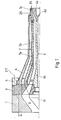
- the extrusion head shown in the drawings shown in its entirety only in FIG. 1, essentially consists of an adapter piece 1, which is flanged with its left end face 2 in FIG. 1 against the corresponding end face of a screw extruder, a nozzle jacket 4, which is by means of one of the indicated screws on the outer area of the mandrel holder 3, the clamping ring 5 is clamped against the mandrel holder and thus also against the adapter piece, an inner mandrel 6 projecting from the mandrel holder and a hollow mandrel 7 which extends coaxially to the inner mandrel 6 within the nozzle casing 4 and which, in principle, flows downstream of the tubular melt channel 8 Mandrel holder divides into two concentric melt channels 9 and 10, from whose right ends in Figure 1, the plastic melt strands emerge to form the two concentric tubes.
- Corrugation tools for the outer tube may be connected downstream.
- the hollow mandrel 7 extends from the mandrel holder 3 to the nozzle outlet openings 25 and 26.
- this tapering region is followed by a relatively long region with a cylindrical, coaxial configuration of the two Melt channels 9 and 10, the so-called ironing section.
- This is followed again by a short end region of both melt channels, in which the average diameter of these channels is increased again. This compensates for a residual tendency of the melt, which is elastic even in the liquid state, to expand again to a larger diameter.
- the mandrel holder 3 is clamped against the adapter piece by means of only schematically indicated screws 12. It can be centered against this in a form-fitting manner, or else by appropriate adjustment and adjustment of the position of the mandrel holder.
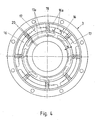
- the mandrel holder 3 has in principle the shape of a ring with parallel end faces, the end face lying downstream with respect to the melt flow carrying a collar 14 which is provided with a thread on both its radially inner and its radially outer side, as can be seen in FIG. 2 onto which the two coaxial parts 7a and 7b of the hollow mandrel 7 are screwed, as can be seen in FIG. 1.
- the collar 14 in FIG. 2 can, for example, also carry a short, thread-free extension on the right, against which corresponding inner surfaces of the two parts of the hollow mandrel then bear in a centering manner.
- the webs 18 extend between the flow channels and run essentially radially in the inflow region of the mandrel holder , but then twist because, as can best be seen from FIG. 4, the throughflow openings 17, which run radially inward in the direction of flow, widen almost twice in the circumferential direction, so that the outlet opening of these channels, the contour shown at 17a in FIG having.
- the through-flow channels 16, which are inclined outward in the direction of flow double, so that their outlet openings have the contour 18a, which is partly visible in FIG. 4 and partly only indicated by dash-dotted lines.
- the outlet areas of the channels 16 and 17 overlap to a considerable extent in order to at least partially compensate for the reduction in the radial extent of these channels from the dimension a at the inlet to the dimension b at the outlet.
- the webs 18 that have remained between the channels are sharp-edged at the inlet and extend to the outlet area according to the general principles of fluid mechanics.
- the outlet openings of the through-flow channels 16 and 17 radially between them have an all-round ring region, the radial extent of which is indicated in FIG. 4 at c.
- the collar 14 protrudes from this ring area.
- the design of the throughflow channels or the webs 18 defined by the boundary surfaces of these throughflow channels allows a favorable distribution of the melt flow over the two melt channels 9 and 10 and at the same time brings about an advantageous mixing of the melt in these two channels.
- the nozzle jacket 4 can be centered against the mandrel holder 3 by means of a corresponding shoulder, or can be held in a freely adjustable manner by the clamping ring 5.
- the hollow mandrel 7 screwed onto the collar 14 consists of an outer hollow mandrel tube 7a and an inner hollow mandrel tube 7b. Each tube is screwed to the collar 14 and centered against it.
- the outer tube 7a in front of the outlet opening is widened. Since the melt channel 10 also widens outwards again in the outlet area, in order to enable assembly of the two tubes 7a and 7b, the end of the inner tube 7b on the nozzle opening side is formed by a separate part 7c which is subsequently screwed on and at the same time also the outlet side end of the centered outer tube 7a.
- the extension of the inner mandrel 6 at the outlet end is formed by a separate component 6 a which is screwed onto the inner mandrel 6.
- the inner mandrel 6 consists of a main part 6b, which also carries the end part 6a and an end part 6c.
- the main part 6b is screwed to the internal thread 24 (FIG. 2) of the mandrel holder and centered against it in a suitable manner.
- the end part 6c of the inner mandrel 6 projects with a collar centered into the recess 26 of the mandrel holder and is held thereon by means of a tension screw which is screwed into the part 6c on the one hand and on the other hand abuts the surface 6d of the inner mandrel main part 6b.
- the mandrel holder carries properly guided and centers not only the inner mandrel, but also the hollow mandrel in the inventive design.
- the hollow mandrel need not necessarily be carried directly by the mandrel holder. Rather, it can only be mounted on the mandrel holder.
- the mandrel holder 3 shown can be divided into two parts by a parting line, as shown by dash-dotted lines at 28 in FIG. 2, the part carrying the collar 14 then no longer strictly belonging to the mandrel holder 3, since this part no longer has the inner mandrel wearing.
- the invention is not limited to the manufacture of round tubes.
- the nozzle profile can also be out of round, for example a tunnel profile.
Priority Applications (1)
| Application Number | Priority Date | Filing Date | Title |
|---|---|---|---|
| EP86105837A EP0243516A1 (fr) | 1986-04-28 | 1986-04-28 | Dispositif pour l'extrusion d'un tube en matière plastique à double paroi |
Applications Claiming Priority (1)
| Application Number | Priority Date | Filing Date | Title |
|---|---|---|---|
| EP86105837A EP0243516A1 (fr) | 1986-04-28 | 1986-04-28 | Dispositif pour l'extrusion d'un tube en matière plastique à double paroi |
Publications (1)
| Publication Number | Publication Date |
|---|---|
| EP0243516A1 true EP0243516A1 (fr) | 1987-11-04 |
Family
ID=8195090
Family Applications (1)
| Application Number | Title | Priority Date | Filing Date |
|---|---|---|---|
| EP86105837A Withdrawn EP0243516A1 (fr) | 1986-04-28 | 1986-04-28 | Dispositif pour l'extrusion d'un tube en matière plastique à double paroi |
Country Status (1)
| Country | Link |
|---|---|
| EP (1) | EP0243516A1 (fr) |
Cited By (4)
| Publication number | Priority date | Publication date | Assignee | Title |
|---|---|---|---|---|
| DE4128654A1 (de) * | 1991-08-29 | 1993-03-04 | Wolfgang Mayer | Mehrschichtiges leitungsrohr aus kunststoff und vorrichtung zu dessen herstellung |
| GB2326613A (en) * | 1997-06-23 | 1998-12-30 | Pirelli General Plc | Plastics extrusion |
| EP1215032A1 (fr) * | 2000-12-15 | 2002-06-19 | FRÄNKISCHE ROHRWERKE GEBR. KIRCHNER GmbH & Co KG | Corps de buse pour le coextrusion |
| CN100427292C (zh) * | 2005-03-18 | 2008-10-22 | 陈亦锋 | 用于包装袋生产的共挤模头 |
Citations (9)
| Publication number | Priority date | Publication date | Assignee | Title |
|---|---|---|---|---|
| CH392867A (de) * | 1962-05-18 | 1965-05-31 | Stanniolfabrik Burgdorf Ag | Düsenkopf zur Herstellung porenfreier Kunststoffschläuche |
| GB994567A (en) * | 1964-04-30 | 1965-06-10 | Gnii Plasticheskykh Mass | Double-wall tube and die for extruding the same |
| CH491737A (de) * | 1969-08-21 | 1970-06-15 | Conduco Ag | Spritzkopf für die Erzeugung von rohrförmigen Vorformlingen |
| US3756758A (en) * | 1969-07-15 | 1973-09-04 | Chemplex Co | Extrusion die for plastic film |
| US3802825A (en) * | 1969-11-11 | 1974-04-09 | Windmoeller & Hoelscher | Extruder for plastic material having a flow divider and means for maintaining the same distribution of temperature gradients in the divided flow |
| DE2403618A1 (de) * | 1974-01-25 | 1975-08-07 | Fraenk Isolierrohr & Metall | Vorrichtung zum herstellen eines doppelwandigen kunststoffrohres |
| DE2528278A1 (de) * | 1975-06-25 | 1976-12-30 | Berner Geb | Heissiegelfaehige folie, sowie verfahren zum herstellen und verwendung einer solchen folie |
| FR2421048A1 (fr) * | 1978-03-30 | 1979-10-26 | Cincinnati Milacron Austria | Dispositif d'extrusion de matiere plastique |
| EP0113041A1 (fr) * | 1982-12-06 | 1984-07-11 | Windmöller & Hölscher | Procédé et dispositif pour former et regrouper des flux partiels de masses thermoplastiques et/ou élastomères refoulées par une extrudeuse |
-
1986
- 1986-04-28 EP EP86105837A patent/EP0243516A1/fr not_active Withdrawn
Patent Citations (9)
| Publication number | Priority date | Publication date | Assignee | Title |
|---|---|---|---|---|
| CH392867A (de) * | 1962-05-18 | 1965-05-31 | Stanniolfabrik Burgdorf Ag | Düsenkopf zur Herstellung porenfreier Kunststoffschläuche |
| GB994567A (en) * | 1964-04-30 | 1965-06-10 | Gnii Plasticheskykh Mass | Double-wall tube and die for extruding the same |
| US3756758A (en) * | 1969-07-15 | 1973-09-04 | Chemplex Co | Extrusion die for plastic film |
| CH491737A (de) * | 1969-08-21 | 1970-06-15 | Conduco Ag | Spritzkopf für die Erzeugung von rohrförmigen Vorformlingen |
| US3802825A (en) * | 1969-11-11 | 1974-04-09 | Windmoeller & Hoelscher | Extruder for plastic material having a flow divider and means for maintaining the same distribution of temperature gradients in the divided flow |
| DE2403618A1 (de) * | 1974-01-25 | 1975-08-07 | Fraenk Isolierrohr & Metall | Vorrichtung zum herstellen eines doppelwandigen kunststoffrohres |
| DE2528278A1 (de) * | 1975-06-25 | 1976-12-30 | Berner Geb | Heissiegelfaehige folie, sowie verfahren zum herstellen und verwendung einer solchen folie |
| FR2421048A1 (fr) * | 1978-03-30 | 1979-10-26 | Cincinnati Milacron Austria | Dispositif d'extrusion de matiere plastique |
| EP0113041A1 (fr) * | 1982-12-06 | 1984-07-11 | Windmöller & Hölscher | Procédé et dispositif pour former et regrouper des flux partiels de masses thermoplastiques et/ou élastomères refoulées par une extrudeuse |
Cited By (7)
| Publication number | Priority date | Publication date | Assignee | Title |
|---|---|---|---|---|
| DE4128654A1 (de) * | 1991-08-29 | 1993-03-04 | Wolfgang Mayer | Mehrschichtiges leitungsrohr aus kunststoff und vorrichtung zu dessen herstellung |
| GB2326613A (en) * | 1997-06-23 | 1998-12-30 | Pirelli General Plc | Plastics extrusion |
| EP1215032A1 (fr) * | 2000-12-15 | 2002-06-19 | FRÄNKISCHE ROHRWERKE GEBR. KIRCHNER GmbH & Co KG | Corps de buse pour le coextrusion |
| DE10062590A1 (de) * | 2000-12-15 | 2002-07-04 | Kirchner Fraenk Rohr | Düsenanordnung zur Coextrusion |
| US6793475B2 (en) | 2000-12-15 | 2004-09-21 | Frankische Rohrwerke Gebr. Kirchner Gmbh & Co. Kg | Coextrusion nozzle arrangement |
| DE10062590B4 (de) * | 2000-12-15 | 2005-12-29 | Fränkische Rohrwerke Gebr. Kirchner GmbH + Co. KG | Düsenanordnung zur Coextrusion |
| CN100427292C (zh) * | 2005-03-18 | 2008-10-22 | 陈亦锋 | 用于包装袋生产的共挤模头 |
Similar Documents
| Publication | Publication Date | Title |
|---|---|---|
| EP0563575B1 (fr) | Procédé et dispositif de production en continu d'un tube composite avec manchon | |
| DE19835189C2 (de) | Vorrichtung zur kontinuierlichen Herstellung von nahtlosen Kunststoffrohren | |
| DE2654001C2 (de) | Vorrichtung zum Herstellen von aus thermoplastischem Kunstoff bestehenden Hohlkörpern | |
| DE1233571B (de) | Verfahren und Vorrichtung zum Durchfuehren plastischen Materials von einer Plastifiziereinrichtung durch einen Durchflusskopf zu einer Duese zum Auspressen eines Stranges, insbesondere zum Herstellen eines Hohlkoerpers aus thermoplastischem Kunststoff nach dem Blasverfahren | |
| DE4240268A1 (de) | Verfahren und Vorrichtung zur fortlaufenden Herstellung eines Verbundrohres mit einem außen im wesentlichen glatten Abschnitt | |
| DE2718537B2 (de) | Extrudierelnrichtung zum Herstellen eines aus wenigstens zwei Schichten bestehenden Verbundrohres aus thermoplastischen Kunststoffen | |
| EP0118692A2 (fr) | Torpille pour le mandrin d'une tête d'extrusion de paraisons pour la fabrication de sections de tuyaux ou de tuyaux en matière thermoplastique | |
| DE2403618A1 (de) | Vorrichtung zum herstellen eines doppelwandigen kunststoffrohres | |
| DE1504253C3 (de) | Längsspritzkopf mit Dorn zum Herstellen von Hohlprofilen | |
| DE202007016630U1 (de) | Vorrichtung zur fortlaufenden Herstellung eines Verbundrohres mit Rohrmuffe | |
| EP1577075B1 (fr) | Dispositif pour la production de tubes plastiques | |
| EP0243516A1 (fr) | Dispositif pour l'extrusion d'un tube en matière plastique à double paroi | |
| DE2911833C3 (de) | Gerader Spritzkopf zum Extrudieren zweier zueinander konzentrischer Kunststoffrohre | |
| DE19719220C2 (de) | Querspritzkopf einer Extrusionsanlage | |
| DE2821559A1 (de) | Ventilsystem zur steuerung der stroemung eines geschmolzenen polymers | |
| DE102010023300B4 (de) | Wendelverteiler, Blaskopf, Blasfolienanlage, Verfahren zum Herstellen einer Blasfolie | |
| AT393808B (de) | Werkzeug zur herstellung von rohren mit unterschiedlichen wanddicken | |
| DE202019105683U1 (de) | Extrusionstechnik zur Bildung von Kunststoff-Vorformlingen und Profilierungstechnik | |
| DE2554238C2 (de) | Vorrichtung zum steglosen Extrudieren von Hohlprofilen | |
| DE1139970B (de) | Umlenk-Spritzkopf fuer Schneckenpressen | |
| EP2049318B1 (fr) | Tête d'injection pour une machine à onduler pour la fabrication de tubes en matière plastique | |
| DE3525530A1 (de) | Verfahren zur herstellung eines mit innenbeschichtung versehenen kunststoffschlauches und extruderkopf zur durchfuehrung des verfahrens | |
| EP2140998A1 (fr) | Dispositif de refroidissement interne à haute puissance | |
| DE3332262C2 (de) | Spritzwerkzeug für eine Kunststoff-Schneckenstrangpresse | |
| EP0876895A1 (fr) | Outil d'extrusion et procédé pour sa fabrication |
Legal Events
| Date | Code | Title | Description |
|---|---|---|---|
| PUAI | Public reference made under article 153(3) epc to a published international application that has entered the european phase |
Free format text: ORIGINAL CODE: 0009012 |
|
| AK | Designated contracting states |
Kind code of ref document: A1 Designated state(s): AT BE CH DE FR GB IT LI LU NL SE |
|
| RBV | Designated contracting states (corrected) |
Designated state(s): AT DE FR GB NL SE |
|
| 17P | Request for examination filed |
Effective date: 19880429 |
|
| 17Q | First examination report despatched |
Effective date: 19890725 |
|
| STAA | Information on the status of an ep patent application or granted ep patent |
Free format text: STATUS: THE APPLICATION IS DEEMED TO BE WITHDRAWN |
|
| 18D | Application deemed to be withdrawn |
Effective date: 19911105 |
|
| RIN1 | Information on inventor provided before grant (corrected) |
Inventor name: GRUELL, HELMUT Inventor name: RAHN, HORST |