EP0563406B1 - Method of laser piercing - Google Patents
Method of laser piercing Download PDFInfo
- Publication number
- EP0563406B1 EP0563406B1 EP93908766A EP93908766A EP0563406B1 EP 0563406 B1 EP0563406 B1 EP 0563406B1 EP 93908766 A EP93908766 A EP 93908766A EP 93908766 A EP93908766 A EP 93908766A EP 0563406 B1 EP0563406 B1 EP 0563406B1
- Authority
- EP
- European Patent Office
- Prior art keywords
- duty ratio
- piercing
- pulse frequency
- processing
- time
- Prior art date
- Legal status (The legal status is an assumption and is not a legal conclusion. Google has not performed a legal analysis and makes no representation as to the accuracy of the status listed.)
- Expired - Lifetime
Links
Images


Classifications
-
- B—PERFORMING OPERATIONS; TRANSPORTING
- B23—MACHINE TOOLS; METAL-WORKING NOT OTHERWISE PROVIDED FOR
- B23K—SOLDERING OR UNSOLDERING; WELDING; CLADDING OR PLATING BY SOLDERING OR WELDING; CUTTING BY APPLYING HEAT LOCALLY, e.g. FLAME CUTTING; WORKING BY LASER BEAM
- B23K26/00—Working by laser beam, e.g. welding, cutting or boring
- B23K26/36—Removing material
- B23K26/38—Removing material by boring or cutting
- B23K26/382—Removing material by boring or cutting by boring
Definitions
- the present invention relates to a piercing method to be carried out at the start of processing in cutting a workpiece by means of a laser processing machine.
- piercing operation In laser processing in which a laser beam is applied to a workpiece for cutting, piercing operation must be performed at the start of the cutting work. This piercing operation is extremely difficult if the workpiece is a mild steel plate having a thickness of 9 mm or more, in particular. This is because the mild steel plate, which constitutes the workpiece, is susceptible to oxidation by oxygen to be used as an assistant gas, and the oxidation is liable to be excessively promoted by the laser beam, thereby causing an increase of scattered molten metal (sputters) and a thermal runaway.
- the piercing operation is carried out while repeating ON and OFF for the supply of the laser beam so that heating by the laser beam and cooling by a jet of the assistant gas alone can be repeated alternately.
- the piercing operation is performed with the output of the laser beam maintained constant, that is, with the peak value, frequency, and pulse duty ratio of laser pulses maintained constant, from the start to end of the processing.
- the processing time is shortened by increasing the peak value of the laser pulses so that the piercing depth for each cycle of operation can be increased.
- the power supply capacity must be increased, which entails higher equipment costs.
- the high peak value makes the processing unstable, which ends up with a higher degree of fluctuation of the processing time.
- the high peak value results in increased sputters, which may adhere to the inside of a processing nozzle, thereby clogging the nozzle, or damaging a focussing lens. Furthermore, it is hard to maintain stable processing over a prolonged period of time, and the peak output, in general, can be maintained only for a very short period of time, so that a resulting hole is too small for the normal cutting work to be started on completion of the piercing operation.
- WO-A-86-02301 discloses a method according to the preambles of attached claims 1 and 8, wherein it is possible to preset (for each laser light pulse) the peak power, spot size and pulse spacial shape. Different pulse trains can be stored for different materials.
- GB-A-2 218 660 states that in laser drilling, it is possible to control the power amplitudes and durations of pulses in order to achieve optimum drilling.
- the object of the present invention is to provide a piercing method in which stable processing can be accomplished in a short time, control is easy, and dispersion of the processing time is minor.
- processing is started with an initial pulse frequency and an initial pulse duty ratio, and the pulse frequency and the pulse duty ratio are increased by predetermined increments with every passage of a first predetermined time.
- the pulse frequency and the pulse duty ratio are successively increased by stages. After this increase is repeated a predetermined number of times, or after the passage of a predetermined time from the start of processing, piercing operation is continued to the end with the last set pulse frequency and the pulse duty ratio maintained.
- the initial pulse frequency, the initial pulse duty ratio, the predetermined time for each step of phased increase, the predetermined increments of the pulse frequency and the pulse duty ratio, and the frequency of increase or the time elapsed after the start of processing, whereafter the increase of the pulse frequency and the pulse duty ratio is to be terminated, may be changed depending on the thickness of a workpiece to be processed and the peak output of the laser.
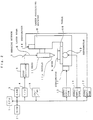
- Fig. 2 is a block diagram of an NC laser processing apparatus for carrying out a piercing control method according to the present invention.
- a processor 1 Based on a control program stored in a ROM 2, a processor 1 reads out a processing program stored in a memory 3, and controls the operation of the whole NC laser processing apparatus.
- An I/O unit 4 emits a pulsating laser beam 6 in accordance with a control signal from the processor 1. This laser beam is delivered to a laser processing machine 8 after being reflected by a bending mirror 7.
- the laser processing machine 8 is provided with a table 10, on which a workpiece 9 is fixed, and a head 11 for applying the laser beam 6 to the workpiece 9.
- the laser beam 6 guided into the head 11 is focussed by a lens (not shown) in a nozzle 11a, and is applied to the workpiece 9.
- the laser processing machine 8 is provided with servomotors 12 and 13 for moving the table 10 in two directions perpendicular to each other or along X- and Y-axes respectively and a servomotor 14 for vertically moving the head 11.
- These servomotors 12, 13 and 14 are connected to servo amplifiers 15, 16 and 17, respectively, and are controllably rotated in response to axis control signals from the processor 1. Instructions are given to the laser processing machine 8 through a CRT/MDI 18.
- the NC laser apparatus is constructed in the same manner as a conventional NC laser apparatus, and a detailed description thereof is omitted.
- piercing operation is started with use of laser pulses with a predetermined initial pulse frequency P 0 and pulse duty ratio Q 0 , and the pulse frequency and the pulse duty ratio are increased by stages, that is, by increments P and Q, respectively, with every passage of a predetermined time T.
- the pulse frequency and the pulse duty ratio are increased a predetermined number N of times, or after the passage of a predetermined period of time T 1 from the start of the processing, the piercing operation is continued without changing an increased pulse frequency P N and pulse duty ratio Q N till a piercing completion time T 2 is reached.
- the pulse frequency and the pulse duty ratio which have initially been set to small values, by stages, the piercing operation can be accomplished in a short period of time without causing a thermal runaway, and dispersion of the processing time can be reduced.
- Figs. 3 to 25 show the results of experiments made in order to obtain optimum values for the above parameters P 0 , Q 0 , P, Q, T and N.
- Laser oscillators C2000 and C3000 from Fanuc Ltd. were used in the individual experiments the results of which are shown in Figs. 3 to 25.
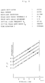
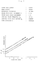
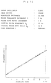
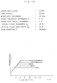
- Fig. 3 shows the results of an experiment conducted with the initial pulse duty ratio Q 0 varied under the following conditions.
- Laser oscillator C2000 Workpiece thickness: 12 mm Peak output: 2,500 W
- Initial pulse frequency P 0 10 Hz
- Initial pulse duty ratio Q 0 15%, 20%, 25%, 30%
- Pulse frequency increment P 5 Hz
- Pulse duty ratio increment Q 1%
- Time interval T 500 msec
- the ranges defined by solid lines are piercing completion sections, and circles in these sections represent the average times required for the completion of processing.
- the circle indicates that the processing is finished in about 6 seconds.
- the piercing time can be shortened by increasing the pulse duty ratio Q 0 at the start of processing.
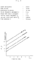
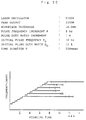
- Fig. 4 shows the results of an experiment conducted with the pulse frequency P 0 at the start of processing, among the processing conditions shown in Fig. 3, changed to 50 Hz, and with other conditions unchanged.
- black spots represent locations where thermal runaways have occurred.
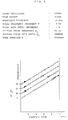
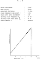
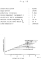
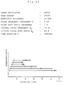
- Fig. 5 shows the results of an experiment conducted with the initial pulse duty ratio Q 0 varied under the following conditions.
- Laser oscillator C3000 Workpiece thickness: 12 mm Peak output: 3,500 W
- Initial pulse frequency P 0 5 Hz
- Initial pulse duty ratio Q 0 7%, 10%, 15%
- Pulse frequency increment P 5 Hz
- Pulse duty ratio increment Q 1%
- Time interval T 500 msec
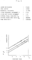
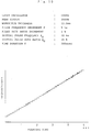
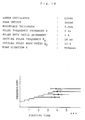
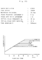
- Fig. 6 shows the results of an experiment conducted with the initial pulse frequency P 0 , among the processing conditions shown in Fig. 5, changed to 10 Hz.
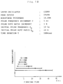
- Fig. 7 shows the results of an experiment conducted with the workpiece thickness, among the processing conditions shown in Fig. 6, changed to 16 mm.
- Fig. 8 shows the results of an experiment conducted with the initial pulse frequency P 0 , among the processing conditions shown in Fig. 7, changed to 5 Hz.
- Figs. 9 to 12 are graphs showing the results of experiments conducted with the time interval for phased increase of the pulse frequency and the pulse duty ratio, that is, time duration T for each step, varied under the following conditions, in order to obtain an optimum value for the time duration T.
- Laser oscillator C3000 Workpiece thickness: 12 mm Peak output: 3,500 W
- Initial pulse frequency P 0 10 Hz
- Initial pulse duty ratio Q 0 15%
- Pulse frequency increment P 5 Hz
- Pulse duty ratio increment Q 1%
- the time interval T is 200 msec in Fig. 9, 300 msec in Fig. 10, 400 msec in Fig. 11, and 500 msec in Fig. 12.
- Figs. 13 to 28 are graphs showing the results of experiments in which the processing time was determined with the number of times N of the phased increase of the pulse frequency and the pulse duty ratio varied.
- Fig. 13 shows the results of an experiment conducted with the number of times N for increase varied under the following conditions.
- Laser oscillator C2000 Workpiece thickness: 9 mm Peak output: 2,500 W
- Initial pulse frequency P 0 10 Hz
- Initial pulse duty ratio Q 0 23%
- Pulse frequency increment P 5 Hz
- Pulse duty ratio increment Q 1%
- Time interval T 300 msec
- Fig. 14 shows the results of an experiment conducted with the time interval T changed to 500 msec, indicating that the processing time is shorter with the time interval T at 300 msec, and becomes longer and undergoes a higher degree of dispersion if the increase number of times N is too low or too high. According to this experiment, it can be comprehended that the processing time is short and its dispersion is minor with the time interval T at 300 msec and the number of times N for increase ranging from about 9 to 11.
- Fig. 15 shows the results of an experiment conducted with the workpiece thickness, among the processing conditions shown in Fig. 13, changed to 12 mm. In this case, it can be comprehended that the processing time becomes shorter, and its dispersion becomes smaller when the number of times N for increase ranges from about 9 to 11.
- Fig. 16 shows the results of an experiment conducted with the workpiece thickness, among the processing conditions shown in Fig. 14, changed to 12 mm. In this case, it can be comprehended that the processing time become shorter and its dispersion becomes smaller when the number of times N for increase is 11.
- Fig. 17 shows the results of an experiment conducted with the workpiece thickness, among the processing conditions shown in Fig. 13, changed to 16 mm
- Fig. 18 shows the results of an experiment conducted with the workpiece thickness, among the processing conditions shown in Fig. 14, changed to 16 mm.
- the time interval T is 300 msec in the case shown in Fig. 17 and 500 msec in the case shown in Fig. 18.
- N optimum: 10 or 11
- Figs. 19 and 20 show the results of experiments conducted with the time interval T varied under the following conditions.
- Laser oscillator C3000 Workpiece thickness: 16 mm Peak output: 3,500 W
- Initial pulse frequency P 0 10 Hz
- Initial pulse duty ratio Q 0 15%
- Pulse frequency increment P 5 Hz
- Pulse duty ratio increment Q 1%
- the time interval T is 300 msec in Fig. 19 and 500 msec in Fig. 20.
- Figs. 21 and 22 show the results of experiments conducted with the time interval T varied under the following conditions: Laser oscillator: C2000 Workpiece thickness: 19 mm Peak output: 2,500 W Initial pulse frequency P 0 : 10 Hz Initial pulse duty ratio Q 0 : 23% Pulse frequency increment P: 5 Hz Pulse duty ratio increment Q: 1%
- the time interval T is 300 msec in Fig. 21 and 500 msec in Fig. 22.
- Figs. 23 to 25 show the results of experiments in which workpieces of different thicknesses were processed under the following conditions: Laser oscillator: C3000 Peak output: 3,500 W Initial pulse frequency P 0 : 10 Hz Initial pulse duty ratio Q 0 : 15% Pulse frequency increment P: 5 Hz Pulse duty ratio increment Q: 1% Time interval T: 500 msec
- the workpiece thickness is 19.0 mm in Fig. 23 and 22.0 mm in Fig. 25.
- the processing time increase and undergoes a higher degree of dispersion if the number of times N for the increase of the pulse frequency and the pulse duty ratio is too low or too high, and there is an optimum increase number of times N, at which the processing time can be shortened and its dispersion can be reduced, that is, when the increase number of times N ranges from 14 to 17.
- Table 1 shows piercing times under the various conditions.
- Table 1 WORKPIECE THICKNESS (mm) PEAK OUTPUT (W) INITIALIZATION CONDITIONS INCREMENT/STEP TIME DURATION (msec) INCREASE FREQUENCY PIERCING TIME (sec) FREQUENCY (Hz) DUTY (%) FREQUENCY (Hz) DUTY (%) 9 1500 10 30 5 1 500 12 6.0 ⁇ 1.0 2500 10 23 5 1 300 9 3.5 ⁇ 0.5 2500 10 23 5 1 500 9 3.9 ⁇ 0.5 12 1500 10 30 5 1 500 19 10.0 ⁇ 1.0 2500 10 23 5 1 300 10 5.8 ⁇ 0.5 2500 10 23 5 1 500 11 7.0 ⁇ 0.5 16 2500 10 23 5 1 300 11 11.7 ⁇ 1.0 2500 10 23 5 1 500 11 12.6 ⁇ 1.0 3500 10 15 5 1 500 10 8.8 ⁇ 1.0 19 2500 10 23 5 1 300 12 17.6 ⁇ 3.0 2500 10 23 5
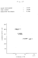
- Figs. 26 to 31 show the results of experimental determinations of the processing time for a conventional piercing method, in which piercing operation is performed with a fixed laser output by maintaining the peak value, frequency, and pulse duty ratio of laser pulses constant from the start to end of the processing.
- Fig. 26 is a graph showing the piercing time determined when a mild steel plate of 9-mm thickness was processed with different constant average outputs (average output varies depending on the pulse frequency and pulse duty ratio) and with the peak output of 1,500 W by using laser oscillators C1500 and C2000 from Fanuc Ltd. under basic conditions (C) and (D), respectively.
- Optical path length about 5.0 m
- Focal distance of lens 12.7 cm (5.00 inches)
- Nozzle stand-off 1.0 mm
- Nozzle hole diameter 1.5 mm
- Assist gas (oxygen) pressure 29419.9 Pascals (0.30 kg/cm 2 )
- Focal position cutting position
- Optical path length about 5.0 m
- Focal distance of lens 19.05 cm (7.50 inches)
- Nozzle stand-off 1.0 mm
- Nozzle hole diameter 2.0 mm
- Assist gas (oxygen) pressure 29419.9 Pascals (0.30 kg/cm 2 )
- Focal position cutting position
- triangles represent the result of one experiment of piercing operation; horizontal bars indicate ranges of the dispersion of the processing end time defined when a plurality of experiments were made under the same conditions, while circles represent average processing times.
- piercing a plate of 9-mm thickness requires at least about 9 seconds.
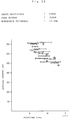
- Fig. 27 is a graph showing the piercing time determined when a mild steel plate of 9-mm thickness was processed with various constant average outputs and with the peak output of 2,500 W by using the laser oscillator C2000 under basic conditions (D). In this case too, the minimum piercing time ranges from 5 to 6 seconds.
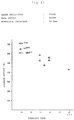
- Fig. 28 shows the results of an experiment, in which a mild steel plate of 12-mm thickness was pierced with the peak output changed to 1,500 W among the following conditions shown in Fig. 26.
- the minimum processing time is 20 seconds or thereabouts.
- Fig. 29 shows the results of an experiment in which a mild steel plate of 12-mm thickness was pierced under the same conditions as the experiment of Fig. 27.
- Fig. 30 shows the results of an experimental determination of the piercing time obtained when a mild steel plate of 12.0-mm thickness was processed with the peak output of 3,500 W by using the laser oscillator C3000 under the following basic conditions (E).
- Optical path length about 6.0 m
- Focal distance of lens 19.05 cm (7.50 inches)
- Nozzle stand-off 2.0 mm
- Nozzle hole diameter 3.0 mm
- Assist gas (oxygen) pressure 9806.6 Pascals (0.10 kg/cm 2 )
- Focal position cutting position
- Fig. 31 shows the results of an experimental determination of the piercing time obtained when a mild steel plate of 16.0-mm thickness was processed with the peak output of 3,500 W by using the laser oscillator C3000 under the following basic conditions (F).
- Optical path length about 6.0 m
- Focal distance of lens 19.05 cm (7.50 inches)
- Nozzle stand-off 2.0 mm or 1.0 mm
- Nozzle hole diameter 3.0 mm or 2.0 mm
- Assist gas (oxygen) pressure 9806.6 or 19613.3 Pascals (0.10 or 0.2 kg/cm 2 )
- Focal position cutting position
- Table 3 shows the values of the individual parameters and their corresponding processing times obtained by the aforementioned experiments when processing was carried out attaching importance to the speed according to the conventional piercing method.
- Table 3 WORKPIECE THICKNESS (mm) PEAK OUTPUT (W) FREQUENCY (Hz) DUTY (%) AVERAGE OUTPUT (W) PIERCING TIME (sec) 6 1500 100 25 374 1.5 ⁇ 0.5 9 1500 75 25 363 8.0 ⁇ 1.0 2500 25 21 499 5.3 ⁇ 0.5 12 1500 75 30 433 21.0 ⁇ 2.0 2500 25 21 499 15.5 ⁇ 2.0 3500 50 19 708 6.4 ⁇ 1.0 16 2500 75 15 446 55.0 ⁇ 5.0 3500 100 14 643 9.5 ⁇ 3.0
- a mild steel plate of 6-mm thickness can be pierced in 1.5 ⁇ 0.5 seconds even when the importance is attached to speed; however, the piercing time of at least 5.3 ⁇ 0.5 seconds is required when the workpiece has thickness of 9 mm.
- the peak output is 3,500 W, at least 6.4 ⁇ 1.0 seconds is required for the workpiece with thickness of 12 mm, and 9.5 ⁇ 3.0 seconds for the workpiece thickness of 16 mm.
- the NC laser processing apparatus is adjusted to set values of the peak output, initial pulse frequency P 0 at the start of processing, initial pulse duty ratio Q 0 , pulse frequency increment P for each step, pulse duty ratio increment Q, time interval T for each step, and increase frequency (or increase time T 1 ) N for pulse frequency and pulse duty ratio, depending on the laser oscillator to be used, the workpiece thickness, and the style of use, that is, standard or speed-first.
- the processing is started with the initial pulse frequency P 0 and the initial pulse duty ratio Q 0 ; the predetermined pulse frequency increment P and pulse duty ratio increment Q are added with every passage of the predetermined time T; and the increase frequency is counted. Once the set increase number of times N is attained, the processing is continued until the processing is finished without changing the pulse frequency and the pulse duty ratio any further.
- the aforementioned parameters may be manually set through the CRT/MDI 18 or preset in the processing program.
- a table stored with the parameters P 0 , Q 0 , P, Q, T and N is previously stored in a nonvolatile memory or the like, depending on the processing mode, that is, high-speed or normal, as well as depending on the values of the workpiece thickness and the peak output, the processing mode, that is, high-speed or normal, is set, and the workpiece thickness and the peak output are set. Then, the respective values of these parameters are read from the table, and processing control is effected in accordance with the parameter values.
Landscapes
- Engineering & Computer Science (AREA)
- Physics & Mathematics (AREA)
- Optics & Photonics (AREA)
- Plasma & Fusion (AREA)
- Mechanical Engineering (AREA)
- Laser Beam Processing (AREA)
Applications Claiming Priority (3)
| Application Number | Priority Date | Filing Date | Title |
|---|---|---|---|
| JP297811/91 | 1991-10-19 | ||
| JP3297811A JPH05111783A (ja) | 1991-10-19 | 1991-10-19 | レーザ加工における穴明け加工方法 |
| PCT/JP1992/001311 WO1993007987A1 (en) | 1991-10-19 | 1992-10-09 | Method of laser piercing |
Publications (3)
| Publication Number | Publication Date |
|---|---|
| EP0563406A1 EP0563406A1 (en) | 1993-10-06 |
| EP0563406A4 EP0563406A4 (ko) | 1994-05-04 |
| EP0563406B1 true EP0563406B1 (en) | 1996-12-11 |
Family
ID=17851473
Family Applications (1)
| Application Number | Title | Priority Date | Filing Date |
|---|---|---|---|
| EP93908766A Expired - Lifetime EP0563406B1 (en) | 1991-10-19 | 1992-10-09 | Method of laser piercing |
Country Status (6)
| Country | Link |
|---|---|
| US (1) | US5434383A (ko) |
| EP (1) | EP0563406B1 (ko) |
| JP (1) | JPH05111783A (ko) |
| KR (1) | KR970010886B1 (ko) |
| DE (1) | DE69215855T2 (ko) |
| WO (1) | WO1993007987A1 (ko) |
Families Citing this family (12)
| Publication number | Priority date | Publication date | Assignee | Title |
|---|---|---|---|---|
| JP3372302B2 (ja) * | 1993-07-05 | 2003-02-04 | ファナック株式会社 | レーザ出力制御方式 |
| JPH07223084A (ja) * | 1994-02-10 | 1995-08-22 | Fanuc Ltd | レーザ加工装置 |
| US6668454B2 (en) * | 1997-12-10 | 2003-12-30 | Canon Kabushiki Kaisha | Method for manufacturing a liquid-discharging recording head |
| JP4162772B2 (ja) * | 1998-09-09 | 2008-10-08 | 日酸Tanaka株式会社 | レーザピアシング方法およびレーザ切断装置 |
| JP3198095B2 (ja) * | 1998-10-21 | 2001-08-13 | ファナック株式会社 | レーザ加工装置 |
| US6777641B2 (en) | 2002-04-16 | 2004-08-17 | W.A. Whitney Co. | Method and apparatus for laser piercing and cutting metal sheet and plate |
| DE112009001200B4 (de) * | 2008-06-04 | 2016-03-10 | Mitsubishi Electric Corp. | Laserbearbeitungsverfahren und Laserbearbeitungsvorrichtung hierfür |
| JP5248353B2 (ja) * | 2009-01-30 | 2013-07-31 | パナソニック デバイスSunx株式会社 | レーザ加工装置 |
| CN102756214B (zh) * | 2011-04-29 | 2015-07-01 | 大族激光科技产业集团股份有限公司 | 一种激光穿孔加工方法 |
| CN108747018B (zh) * | 2018-05-30 | 2020-12-11 | 山西太钢不锈钢股份有限公司 | 一种奥氏体不锈钢负拼缝间隙焊接方法 |
| DE102020106734A1 (de) | 2020-03-12 | 2021-09-16 | Precitec Gmbh & Co. Kg | Verfahren und Vorrichtung zum Einstechen in ein Werkstück mittels eines Laserstrahls |
| CN113921744B (zh) * | 2021-09-29 | 2023-10-20 | 合肥维信诺科技有限公司 | 激光剥离设备控制方法和装置 |
Family Cites Families (6)
| Publication number | Priority date | Publication date | Assignee | Title |
|---|---|---|---|---|
| WO1986002301A1 (en) * | 1984-10-16 | 1986-04-24 | Advanced Laser Systems, Inc. | Laser drilling apparatus and method |
| JPS61150789A (ja) * | 1984-12-25 | 1986-07-09 | Komatsu Ltd | レ−ザ加工方法 |
| JPS63235086A (ja) * | 1987-03-20 | 1988-09-30 | Fanuc Ltd | レ−ザ発振器制御方法 |
| JPH01197084A (ja) * | 1988-01-29 | 1989-08-08 | Fanuc Ltd | Cncレーザ加工機のパワー制御方式 |
| GB2218660B (en) * | 1988-05-16 | 1991-09-25 | Lumonics Ltd | Method of material processing using a laser beam |
| JPH03230884A (ja) * | 1990-02-06 | 1991-10-14 | Amada Co Ltd | ピアス加工のレーザ出力条件設定方法及び装置 |
-
1991
- 1991-10-19 JP JP3297811A patent/JPH05111783A/ja active Pending
-
1992
- 1992-10-09 EP EP93908766A patent/EP0563406B1/en not_active Expired - Lifetime
- 1992-10-09 WO PCT/JP1992/001311 patent/WO1993007987A1/ja active IP Right Grant
- 1992-10-09 DE DE69215855T patent/DE69215855T2/de not_active Expired - Fee Related
- 1992-10-09 KR KR1019930701285A patent/KR970010886B1/ko not_active IP Right Cessation
- 1992-10-09 US US08/075,580 patent/US5434383A/en not_active Expired - Lifetime
Also Published As
| Publication number | Publication date |
|---|---|
| DE69215855D1 (de) | 1997-01-23 |
| DE69215855T2 (de) | 1997-04-03 |
| WO1993007987A1 (en) | 1993-04-29 |
| JPH05111783A (ja) | 1993-05-07 |
| US5434383A (en) | 1995-07-18 |
| KR930702112A (ko) | 1993-09-08 |
| KR970010886B1 (ko) | 1997-07-02 |
| EP0563406A4 (ko) | 1994-05-04 |
| EP0563406A1 (en) | 1993-10-06 |
Similar Documents
| Publication | Publication Date | Title |
|---|---|---|
| EP0563406B1 (en) | Method of laser piercing | |
| JP2797684B2 (ja) | ノズルの製造方法および製造装置 | |
| JPH04502429A (ja) | レーザービームによって工作物を加工する方法と装置 | |
| US5818009A (en) | Laser beam machining system | |
| EP0358771B1 (en) | Power control system for cnc laser-beam machine tool | |
| US4401876A (en) | Working gemstones | |
| US5777294A (en) | Laser beam machining system and method using preliminary work commands | |
| US6769962B2 (en) | Scraping method | |
| US5449881A (en) | Laser beam machine | |
| WO1997004914A1 (en) | Pulsed laser cladding arrangement | |
| US20040105519A1 (en) | Manufacturing method and device of control rods for nuclear reactors | |
| GB2218660A (en) | Method of material processing using a laser beam | |
| JP3131357B2 (ja) | レーザ加工方法 | |
| EP0770448B1 (en) | Method and apparatus for laser cutting materials | |
| DE112021008400T5 (de) | Laserbearbeitungsvorrichtung und Laserbearbeitungsverfahren | |
| JP2002301583A (ja) | レーザ溶接方法及び装置 | |
| JP2969040B2 (ja) | ダムバーの切断方法 | |
| JP3115060B2 (ja) | レーザ加工方法 | |
| JPH0813430B2 (ja) | レーザ加工装置 | |
| JPH036872B2 (ko) | ||
| Tiffany | Drilling, marking and other applications for industrial Nd: YAG lasers | |
| JPS61289992A (ja) | レ−ザ加工方法 | |
| JPH0327752Y2 (ko) | ||
| JPH09150284A (ja) | 三次元レーザ加工機による開先加工方法 | |
| WO2023172533A1 (en) | Dynamically controlled laser drilling system and method for producing circular holes |
Legal Events
| Date | Code | Title | Description |
|---|---|---|---|
| PUAI | Public reference made under article 153(3) epc to a published international application that has entered the european phase |
Free format text: ORIGINAL CODE: 0009012 |
|
| 17P | Request for examination filed |
Effective date: 19930713 |
|
| AK | Designated contracting states |
Kind code of ref document: A1 Designated state(s): DE GB IT |
|
| A4 | Supplementary search report drawn up and despatched |
Effective date: 19940315 |
|
| AK | Designated contracting states |
Kind code of ref document: A4 Designated state(s): DE GB IT |
|
| 17Q | First examination report despatched |
Effective date: 19950807 |
|
| GRAG | Despatch of communication of intention to grant |
Free format text: ORIGINAL CODE: EPIDOS AGRA |
|
| GRAH | Despatch of communication of intention to grant a patent |
Free format text: ORIGINAL CODE: EPIDOS IGRA |
|
| GRAH | Despatch of communication of intention to grant a patent |
Free format text: ORIGINAL CODE: EPIDOS IGRA |
|
| GRAA | (expected) grant |
Free format text: ORIGINAL CODE: 0009210 |
|
| AK | Designated contracting states |
Kind code of ref document: B1 Designated state(s): DE GB IT |
|
| PG25 | Lapsed in a contracting state [announced via postgrant information from national office to epo] |
Ref country code: IT Free format text: LAPSE BECAUSE OF FAILURE TO SUBMIT A TRANSLATION OF THE DESCRIPTION OR TO PAY THE FEE WITHIN THE PRESCRIBED TIME-LIMIT;WARNING: LAPSES OF ITALIAN PATENTS WITH EFFECTIVE DATE BEFORE 2007 MAY HAVE OCCURRED AT ANY TIME BEFORE 2007. THE CORRECT EFFECTIVE DATE MAY BE DIFFERENT FROM THE ONE RECORDED. Effective date: 19961211 |
|
| REF | Corresponds to: |
Ref document number: 69215855 Country of ref document: DE Date of ref document: 19970123 |
|
| PG25 | Lapsed in a contracting state [announced via postgrant information from national office to epo] |
Ref country code: GB Free format text: LAPSE BECAUSE OF NON-PAYMENT OF DUE FEES Effective date: 19971009 |
|
| PLBE | No opposition filed within time limit |
Free format text: ORIGINAL CODE: 0009261 |
|
| STAA | Information on the status of an ep patent application or granted ep patent |
Free format text: STATUS: NO OPPOSITION FILED WITHIN TIME LIMIT |
|
| 26N | No opposition filed | ||
| GBPC | Gb: european patent ceased through non-payment of renewal fee |
Effective date: 19971009 |
|
| PGFP | Annual fee paid to national office [announced via postgrant information from national office to epo] |
Ref country code: DE Payment date: 20081014 Year of fee payment: 17 |
|
| PG25 | Lapsed in a contracting state [announced via postgrant information from national office to epo] |
Ref country code: DE Free format text: LAPSE BECAUSE OF NON-PAYMENT OF DUE FEES Effective date: 20100501 |