EP0558963A2 - Dispositif tendeur linéaire pour un système de retenue dans un véhicule - Google Patents
Dispositif tendeur linéaire pour un système de retenue dans un véhicule Download PDFInfo
- Publication number
- EP0558963A2 EP0558963A2 EP93102057A EP93102057A EP0558963A2 EP 0558963 A2 EP0558963 A2 EP 0558963A2 EP 93102057 A EP93102057 A EP 93102057A EP 93102057 A EP93102057 A EP 93102057A EP 0558963 A2 EP0558963 A2 EP 0558963A2
- Authority
- EP
- European Patent Office
- Prior art keywords
- piston
- linear drive
- drive according
- traction cable
- damping device
- Prior art date
- Legal status (The legal status is an assumption and is not a legal conclusion. Google has not performed a legal analysis and makes no representation as to the accuracy of the status listed.)
- Granted
Links
Images

Classifications
-
- B—PERFORMING OPERATIONS; TRANSPORTING
- B60—VEHICLES IN GENERAL
- B60R—VEHICLES, VEHICLE FITTINGS, OR VEHICLE PARTS, NOT OTHERWISE PROVIDED FOR
- B60R22/00—Safety belts or body harnesses in vehicles
- B60R22/34—Belt retractors, e.g. reels
- B60R22/46—Reels with means to tension the belt in an emergency by forced winding up
- B60R22/4619—Transmission of tensioning power by cable, e.g. using a clutch on reel side
-
- B—PERFORMING OPERATIONS; TRANSPORTING
- B60—VEHICLES IN GENERAL
- B60R—VEHICLES, VEHICLE FITTINGS, OR VEHICLE PARTS, NOT OTHERWISE PROVIDED FOR
- B60R22/00—Safety belts or body harnesses in vehicles
- B60R22/28—Safety belts or body harnesses in vehicles incorporating energy-absorbing devices
-
- F—MECHANICAL ENGINEERING; LIGHTING; HEATING; WEAPONS; BLASTING
- F16—ENGINEERING ELEMENTS AND UNITS; GENERAL MEASURES FOR PRODUCING AND MAINTAINING EFFECTIVE FUNCTIONING OF MACHINES OR INSTALLATIONS; THERMAL INSULATION IN GENERAL
- F16C—SHAFTS; FLEXIBLE SHAFTS; ELEMENTS OR CRANKSHAFT MECHANISMS; ROTARY BODIES OTHER THAN GEARING ELEMENTS; BEARINGS
- F16C2240/00—Specified values or numerical ranges of parameters; Relations between them
- F16C2240/12—Force, load, stress, pressure
-
- Y—GENERAL TAGGING OF NEW TECHNOLOGICAL DEVELOPMENTS; GENERAL TAGGING OF CROSS-SECTIONAL TECHNOLOGIES SPANNING OVER SEVERAL SECTIONS OF THE IPC; TECHNICAL SUBJECTS COVERED BY FORMER USPC CROSS-REFERENCE ART COLLECTIONS [XRACs] AND DIGESTS
- Y10—TECHNICAL SUBJECTS COVERED BY FORMER USPC
- Y10T—TECHNICAL SUBJECTS COVERED BY FORMER US CLASSIFICATION
- Y10T74/00—Machine element or mechanism
- Y10T74/20—Control lever and linkage systems
- Y10T74/20396—Hand operated
- Y10T74/20402—Flexible transmitter [e.g., Bowden cable]
- Y10T74/2045—Flexible transmitter [e.g., Bowden cable] and sheath support, connector, or anchor
-
- Y—GENERAL TAGGING OF NEW TECHNOLOGICAL DEVELOPMENTS; GENERAL TAGGING OF CROSS-SECTIONAL TECHNOLOGIES SPANNING OVER SEVERAL SECTIONS OF THE IPC; TECHNICAL SUBJECTS COVERED BY FORMER USPC CROSS-REFERENCE ART COLLECTIONS [XRACs] AND DIGESTS
- Y10—TECHNICAL SUBJECTS COVERED BY FORMER USPC
- Y10T—TECHNICAL SUBJECTS COVERED BY FORMER US CLASSIFICATION
- Y10T74/00—Machine element or mechanism
- Y10T74/20—Control lever and linkage systems
- Y10T74/20396—Hand operated
- Y10T74/20402—Flexible transmitter [e.g., Bowden cable]
- Y10T74/20462—Specific cable connector or guide
Definitions
- the invention relates to a linear drive for vehicle restraint systems, with a pyrotechnic gas generator and a piston / cylinder unit which can be activated by the gases generated by the latter, to the piston of which a traction cable is connected.
- a linear drive is particularly required for belt tensioners that are arranged on the belt retractor or at another point on the belt system.
- the invention is based on the finding that an increase in the penalty payment has no or at least no substantial increase Increasing the power of the gas generator can be achieved by making better use of the energy released by it.
- the piston and the pull cable are coupled to one another via a damping device, which limits the force exerted by the piston on the pull cable in the phase of the pressure increase of the gases generated by the gas generator and allows it to increase steadily, preferably progressively.
- the achievable mechanical performance is primarily determined by the axial force acting on the piston, which is generated by the gas pressure acting on the end face of the piston. It is assumed that this force is available in the cylinder over the entire distance of the piston.
- the invention is based on the knowledge that this assumption is incorrect.
- the gas pressure generated by available gas generators initially rises steeply after the gas generator is ignited and already reaches a maximum value after 1 ms or less. The pressure then drops again and has less than about 10% of its maximum value about 3 ms after ignition.
- the vast majority of the energy released by the gas generator is therefore only available for a fraction of the time that the piston takes for a complete stroke of, for example, 200 mm.
- the measure according to the invention according to which the piston and the pull cable are coupled to one another via a damping direction, optimally converts the energy released by the gas generator into accelerating the piston. In particular, it is achieved that the maximum of the piston acceleration coincides at least approximately with the maximum of the gas pressure curve on the time axis.
- the damping should therefore be effective during the entire initial phase of the piston movement, in which the gas pressure generated by the gas generator increases.
- the piston covers a comparatively short distance of approximately 5 to 15% of the total piston stroke.
- the piston covers a distance of only about 16 mm in this initial phase.
- the invention lies further based on the knowledge that a way must be found to store the energy released by the gas generator, which is only available for about 2 to 3 ms in conventional designs, so that the force required for belt tensioning over the entire stroke of the Belt tensioner remains available. It has been found that this storage can only take place mechanically.
- the belt reel with the belt webbing wound thereon can be regarded as an energy store.
- the belt spool must therefore be accelerated to such a speed within 1 to 2 ms that in the subsequent phase, in which the gas pressure has almost collapsed, the moment of inertia of the belt spool and the webbing wound thereon is sufficient to provide the required force over the entire stroke .
- the torque applied to the belt reel should increase steeply after the gas generator has been ignited, but not too abruptly.
- the damping device can be used to set the optimum profile of the torque which becomes effective on the belt reel. It is particularly favorable if the force transmitted from the piston to the traction cable by means of the damping device increases progressively with the distance covered during the phase of the pressure increase.
- a generic linear drive has been known per se, which has a piston to which a tie rod with a force limiting device for the force acting during belt tensioning is connected.
- a desired force limitation in this linear drive is achieved in that when a predetermined limit force is exceeded, a relief valve is opened after the force of a compression spring has been overcome.
- This compression spring is dimensioned so that the relief valve remains closed in the normal working phase of the linear drive.
- the force occurring during the puncturing process should not be limited, but the available energy should be used as completely as possible and in mechanical Driving force are implemented, which is surprisingly achieved by means of the damping device.
- the time period in which the gas pressure is available can also be somewhat longer than 2 to 3 ms and the gas pressure curve drops less steeply.
- the gas pressure also contributes to the drive power during the intermediate and final phases of the piston movement. In principle, however, the vast majority of the energy is released within 2 to 3 ms immediately after ignition, so that the major part of the drive power must then be applied by the mechanical energy that occurs in the rotary movement of the belt reel and the belt webbing located thereon is saved.
- the damping device is an elastically flexible part that is inserted into the force transmission path between the piston and the pull cable;
- the damping device is formed by a plastically deformable part, which is also inserted into the path of the power transmission between the piston and the pull cable.
- Different embodiments of the damping device are specified in the subclaims.
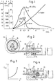
- the pressure curve of the gases generated by a pyrotechnic gas generator is plotted as a curve D as a function of time t.
- 2 schematically shows such a belt tensioner with a piston / cylinder linear drive 10, which engages via a traction cable 12 on the circumference of a pulley 14, which by means of a clamping roller coupling mechanism 16 on a belt reel 18 of a belt retractor can be coupled, on which the belt webbing 20 is wound.
- the linear drive 10 consists of a cylinder 22 and a piston 24 slidably received therein, which acts on the free end of the traction cable 12 and whose end face can be acted upon by high-pressure gases which a gas generator 26 generates as soon as it is triggered by an electrical or mechanical one Detonator is triggered.
- the piston 24 is firmly pressed onto the end of the pull cable 12.
- the gas generator 26 is inserted into a bore in a housing block 28, in which a curved channel 30 is formed, through which the gases generated by the gas generator 26 when it is ignited are led to the end face of the piston 24.
- the gas pressure D initially rises steeply in conventional designs of the gas generator 26 and already reaches a maximum of approximately 76 ⁇ 106 Pa after 0.75 ms. Then the pressure D drops almost as steeply and after about 2.5 ms has only a fraction of about 10% of the maximum gas pressure reached. Almost all of the energy released by the gas generator is available for a short period of 2 to 3 ms. This time period is considerably shorter than that which the piston 24 needs to cover the distance from, for example, 250 mm to the end of the cylinder 22.
- the force exerted by the piston 24 is not transmitted directly to the traction cable 12, but rather via a damping device 32.
- This damping device 32 is formed by a plurality of disc springs which are lined up on the end of the pull cable 12 and are supported on the one hand on the adjacent end face of the piston 24 and on the other hand on a stop part 34 which is firmly pressed onto the end of the pull cable 12.
- Fig. 3 shows the development of the tensile force F built up in the traction cable 12 as a function of the distance s traveled. As can be seen from the diagram, the force F increases progressively in the initial phase of the piston movement.
- the belt reel 18 is now set in rotation by the force F acting on the circumference of the rope pulley 14 and already reaches an extremely high speed after a short movement of the piston of approximately 16 mm.
- the diagram in FIG. 1 also shows the course of the acceleration G of the piston 24 as a function of the time t. It is striking in the diagram that curve G has a similar course to curve D and in particular that its apex is also reached at about 0.75 ms. The gas pressure D is thus optimally converted into acceleration of the piston 24.
- the damping device is effective during the entire initial phase of the piston movement up to approximately 1 ms.
- the piston 24 covers most of the distance to the end of the cylinder 10, for example a total of about 200 mm, with a low pressure. After approximately 2.5 to 3 ms, the piston 24 continues to fly due to its inertia in the cylinder 22. By making relief bores in the wall of the cylinder 10 approximately halfway up the entire length of the cylinder, it was possible to demonstrate that the remaining gas pressure D only makes a small contribution to the penalty performance.
- the belt reel 18 continues its rotational movement essentially due to its moment of inertia.
- the damping device 32 ensures that the force profile (FIG.
- FIGS. 5 and 6 Two further embodiments of the damping device are shown in FIGS. 5 and 6.
- a damping device 32 in the form of a cylindrical body made of elastically flexible material with an axial passage for the traction cable 12 is arranged between the piston 24 and the stop part 34. As shown in Fig. 5b, this body is elastically and at the same time plastically deformed when the tensile stress in the traction cable 12 rises.
- a wall 33 is formed on the piston 24 on its end face facing the stop part 34, the outer surface of which is cylindrical and which defines a frustoconical space 35 which is coaxial with the cylinder 10 and which extends to the free end of the wall 33 expands.
- the stop part 34 penetrates into the outer end of the space 35 in the rest state shown in FIG. 6a. As soon as the tensile force in the traction cable 12 increases, the stop part 34 is pulled further into the space 35, the wall 33 being spread apart and plastically deformed. 6b shows this state.
- a plate which extends essentially transversely to the traction cable forms the expansion body of the stop part 34 for the wall 33.
- the edges on the side of the plate directed towards the wall 33, which is plastically deformed, are rounded.
- the radius of the curve is approximately 1 mm, but can also be approximately 1 to 2 mm.
- the force curve shown in FIG. 3 is achieved in both embodiments (FIGS. 5 and 6).
- the course of the force F can vary depending on the distance s; by dimensioning the damping device, an optimization of the force curve is possible in each case in such a way that the energy released by the gas generator within a short time can be optimally transferred to a tensioning mechanism in order to be stored there as mechanical energy and over a longer period for the tightening of the webbing to be available.
- a cone-shaped ramp surface 40 is formed on the piston 24 by a constriction, at the deepest part of which three balls 42 on only one side of the piston 24 are formed by a guide part 44 elastic material are held in contact on the inside of the cylinder 10.
- the guide part 44 has two shoulders 45 by which the balls 42 are held on the named side of the piston 24.
- the Koblen 24 is slidably supported on the inside of the cylinder 10.
- the balls 42 which now act as locking balls, are brought into engagement with the wall of the cylinder 10, since they are pressed radially outward by the ramp surface 40 will.
- the balls 42 penetrate into the material of the wall of the cylinder 10 and deform it plastically. 7b shows this state.
- the arrangement acts as an energy converter that reduces peak loads in the belt system. By using only a few balls, elastic deformations of the cylinder 10 are avoided, which leads to an inconsistent energy conversion and the occurrence of load fluctuations would lead in the belt system.
- the energy conversion should be carried out with only a few deformation elements, so that each of them with a relatively large depth in the Material of the cylinder wall penetrates.
- a roller 46 is used, which is provided with a rounding at its front ends, so that it can penetrate smoothly and without machining into the material of the cylinder wall.
- the mode of operation is basically the same as in the embodiment according to FIG. 7.
- the piston is divided into two piston parts 24a, 24b, which are loosely lined up on the traction cable 12 at an axial distance from one another.
- a plate is arranged in the space between the piston parts 24a, 24b, which in the rest state shown in FIG. 9a is inclined at an angle of approximately 30 ° to the axis of the cylinder 10.
- the plate 48 is slidably supported at one end on the inside of the cylinder 10 and is provided with two deformation members 48a, 48b at its radially opposite end.
- a wedge-shaped guide part 49 elastically holds the plate 48 with its deforming members 48a, 48b on the inside of the cylinder 10.
- the plate 48 does not resist the movement of the piston 24a, 24b to tighten the webbing; in the opposite movement it straightens up so that the deforming members 48a, 48b penetrate into the material of the wall of the cylinder 10 and plastically deform it. This state is shown in Fig. 9b.
- the mode of operation is basically the same as in the embodiments according to FIGS. 7 and 8.
Applications Claiming Priority (2)
| Application Number | Priority Date | Filing Date | Title |
|---|---|---|---|
| DE4206980 | 1992-03-05 | ||
| DE4206980 | 1992-03-05 |
Publications (3)
| Publication Number | Publication Date |
|---|---|
| EP0558963A2 true EP0558963A2 (fr) | 1993-09-08 |
| EP0558963A3 EP0558963A3 (fr) | 1994-04-27 |
| EP0558963B1 EP0558963B1 (fr) | 1997-10-01 |
Family
ID=6453309
Family Applications (1)
| Application Number | Title | Priority Date | Filing Date |
|---|---|---|---|
| EP93102057A Revoked EP0558963B1 (fr) | 1992-03-05 | 1993-02-10 | Dispositif tendeur linéaire pour un système de retenue dans un véhicule |
Country Status (10)
| Country | Link |
|---|---|
| US (1) | US5350194A (fr) |
| EP (1) | EP0558963B1 (fr) |
| JP (1) | JPH089318B2 (fr) |
| CN (1) | CN1077166A (fr) |
| CZ (1) | CZ279207B6 (fr) |
| DE (1) | DE59307441D1 (fr) |
| ES (1) | ES2047473T3 (fr) |
| HU (1) | HUT70737A (fr) |
| PL (1) | PL171590B1 (fr) |
| RU (1) | RU2058905C1 (fr) |
Cited By (6)
| Publication number | Priority date | Publication date | Assignee | Title |
|---|---|---|---|---|
| EP0616928A1 (fr) * | 1993-03-20 | 1994-09-28 | TRW Occupant Restraint Systems GmbH | Tendeur de sangle pour ceintures de sécurité avec moteur pyrotechnique |
| EP0879741A1 (fr) * | 1997-05-20 | 1998-11-25 | TRW Occupant Restraint Systems GmbH & Co. KG | Prétensionneur de sangle pour un système de retenue d'un occupant de véhicule |
| EP0873919A3 (fr) * | 1997-04-23 | 1999-01-07 | TRW Occupant Restraint Systems GmbH & Co. KG | Prétendeur pour ceinture de sécurité |
| DE20102758U1 (de) * | 2001-02-16 | 2001-06-28 | Trw Repa Gmbh | Gurtstraffer |
| WO2008058580A1 (fr) * | 2006-11-14 | 2008-05-22 | Daimler Ag | Tendeur de ceinture pour un système de ceinture de sécurité |
| US11021131B2 (en) | 2017-01-23 | 2021-06-01 | Volkswagen Aktiengesellschaft | Safety belt device for a vehicle |
Families Citing this family (20)
| Publication number | Priority date | Publication date | Assignee | Title |
|---|---|---|---|---|
| DE4307062A1 (de) * | 1993-03-06 | 1994-09-08 | Trw Repa Gmbh | Gurtstraffer für Sicherheitsgurtsysteme in Fahrzeugen |
| US5531479A (en) * | 1995-01-20 | 1996-07-02 | Trw Vehicle Safety Systems Inc. | Vehicle seat belt restraint system |
| US5639120A (en) * | 1995-09-27 | 1997-06-17 | Ford Motor Company | Seat belt buckle pretensioner with end cap |
| US5564748A (en) * | 1995-09-27 | 1996-10-15 | Ford Motor Company | Seat belt buckle pretensioner with patterned frangible end cap |
| GB9601075D0 (en) * | 1996-01-19 | 1996-03-20 | Alliedsignal Ltd | Pretensioner |
| DE29607362U1 (de) * | 1996-04-23 | 1996-08-22 | Trw Repa Gmbh | Sicherheitsgurtsystem |
| DE29612781U1 (de) * | 1996-07-23 | 1996-11-21 | Trw Repa Gmbh | Pyrotechnische Linearantriebseinrichtung für einen Gurtstraffer |
| US5911433A (en) * | 1997-11-06 | 1999-06-15 | Trw Inc. | Vehicle occupant protection apparatus |
| US6039353A (en) * | 1997-12-24 | 2000-03-21 | Trw Vehicle Safety Systems Inc. | Apparatus for pretensioning seat belt webbing |
| JP3662739B2 (ja) * | 1998-04-20 | 2005-06-22 | 本田技研工業株式会社 | シートベルトのプリテンショナ装置 |
| US20030122363A1 (en) * | 1999-01-11 | 2003-07-03 | Olaf Muller | Operating method and system for vehicle safety device |
| US6167808B1 (en) * | 1999-04-06 | 2001-01-02 | Trw Inc. | Initiator for air bag inflator |
| DE10018487C1 (de) * | 2000-04-14 | 2002-01-24 | Autoliv Dev | Gurtstraffer mit Dämpfungseinrichtung |
| NL1019869C2 (nl) * | 2001-05-11 | 2002-11-12 | Whiplash Preventie Systems Hol | Pyrotechnische bedieningsinrichting en daarmee uitgeruste stoel, alsmede daarin toe te passen dempingsorgaan. |
| JP4622605B2 (ja) * | 2005-03-18 | 2011-02-02 | タカタ株式会社 | 点火器組立体、インフレータ、エアバッグ装置及びシートベルト装置 |
| DE102005049659B3 (de) * | 2005-10-18 | 2007-04-05 | Autoliv Development Ab | Straffeinrichtung für Sicherheitsgurte mit einem oliveförmigen Kolben |
| US7770924B2 (en) * | 2008-07-17 | 2010-08-10 | Autoliv Asp, Inc. | Liquid cooled hybrid |
| DE102011014127A1 (de) * | 2011-03-15 | 2012-09-20 | Trw Automotive Gmbh | Linearantrieb |
| CN103010151B (zh) * | 2011-06-28 | 2015-06-10 | 常州博万达汽车安全设备有限公司 | 用于座椅安全带的预紧器 |
| US9726216B2 (en) * | 2013-02-04 | 2017-08-08 | Shimano Inc. | Cable adjusting unit |
Citations (3)
| Publication number | Priority date | Publication date | Assignee | Title |
|---|---|---|---|---|
| FR2491340A1 (fr) * | 1980-10-06 | 1982-04-09 | Repa Feinstanzwerk Gmbh | Tendeur de rappel pour un enrouleur automatique de ceinture de securite |
| DE3407379A1 (de) * | 1984-02-29 | 1986-06-26 | Autoflug Gmbh, 2084 Rellingen | Gurtstraffer fuer einen selbstsperrenden sicherheitsgurtaufroller |
| GB2217181A (en) * | 1988-03-22 | 1989-10-25 | Autoflug Gmbh | Drive means for safety belt tighteners |
Family Cites Families (14)
| Publication number | Priority date | Publication date | Assignee | Title |
|---|---|---|---|---|
| DE2304878C2 (de) * | 1973-02-01 | 1982-12-30 | Adam Opel AG, 6090 Rüsselsheim | Sicherheitsgurtanordnung für Fahrzeuge, insbesondere für Kraftfahrzeuge |
| JPS49124731U (fr) * | 1973-02-22 | 1974-10-25 | ||
| FR2239870A1 (fr) * | 1973-08-03 | 1975-02-28 | Poudres & Explosifs Ste Nale | |
| DE2540952C2 (de) * | 1975-09-13 | 1984-08-16 | Volkswagenwerk Ag, 3180 Wolfsburg | Gurtspannvorrichtung für einen Sicherheitsgurt |
| DE2809587A1 (de) * | 1977-03-09 | 1978-09-14 | Britax Wingard Ltd | Spannvorrichtung fuer einen sicherheitsgurt |
| DE2727123A1 (de) * | 1977-06-16 | 1978-12-21 | Daimler Benz Ag | Verankerung eines end- oder umlenkpunktes eines sicherheitsgurtes, insbesondere in kraftwagen |
| JPS54153425A (en) * | 1978-05-23 | 1979-12-03 | Nippon Soken Inc | Seat belt tightening apparatus |
| FR2460407A1 (fr) * | 1979-06-29 | 1981-01-23 | Angeviniere Sa | Dispositif de traction a course irreversible |
| JPS607973Y2 (ja) * | 1979-08-02 | 1985-03-19 | 株式会社日本自動車部品総合研究所 | シ−トベルト引締め装置 |
| DE3137263C2 (de) * | 1980-10-06 | 1985-12-19 | TRW Repa GmbH, 7071 Alfdorf | Zylinder/Kolben-Antrieb insbesondere für Rückstrammsysteme in Sicherheitsgurtwickelautomaten |
| US4441738A (en) * | 1980-12-30 | 1984-04-10 | Nippon Soken, Inc. | Seat belt tensioning device |
| DE8406217U1 (de) * | 1984-02-29 | 1985-09-12 | Autoflug Gmbh, 2084 Rellingen | Gurtstraffer für einen selbstsperrenden Sicherheitsgurtaufroller |
| DE3900024A1 (de) * | 1989-01-02 | 1990-07-05 | Schmidt Gmbh R | Sperrvorrichtung fuer mechanischen sicherheitsgurtstrammer |
| EP0398010B1 (fr) * | 1989-05-13 | 1994-11-23 | Hs Technik + Design Technische Entwicklungen Gmbh | Dispositif de blocage et dispositif pour tendre une ceinture de sécurité dans un véhicule, en particulier dans un véhicule automobile |
-
1993
- 1993-02-10 DE DE59307441T patent/DE59307441D1/de not_active Revoked
- 1993-02-10 ES ES93102057T patent/ES2047473T3/es not_active Expired - Lifetime
- 1993-02-10 EP EP93102057A patent/EP0558963B1/fr not_active Revoked
- 1993-02-24 US US08/021,774 patent/US5350194A/en not_active Expired - Fee Related
- 1993-03-02 PL PL93297914A patent/PL171590B1/pl unknown
- 1993-03-03 CN CN93102306A patent/CN1077166A/zh active Pending
- 1993-03-04 CZ CZ93331A patent/CZ279207B6/cs unknown
- 1993-03-04 RU RU9393004576A patent/RU2058905C1/ru active
- 1993-03-04 JP JP5043926A patent/JPH089318B2/ja not_active Expired - Fee Related
- 1993-03-05 HU HU9300616A patent/HUT70737A/hu unknown
Patent Citations (3)
| Publication number | Priority date | Publication date | Assignee | Title |
|---|---|---|---|---|
| FR2491340A1 (fr) * | 1980-10-06 | 1982-04-09 | Repa Feinstanzwerk Gmbh | Tendeur de rappel pour un enrouleur automatique de ceinture de securite |
| DE3407379A1 (de) * | 1984-02-29 | 1986-06-26 | Autoflug Gmbh, 2084 Rellingen | Gurtstraffer fuer einen selbstsperrenden sicherheitsgurtaufroller |
| GB2217181A (en) * | 1988-03-22 | 1989-10-25 | Autoflug Gmbh | Drive means for safety belt tighteners |
Cited By (11)
| Publication number | Priority date | Publication date | Assignee | Title |
|---|---|---|---|---|
| EP0616928A1 (fr) * | 1993-03-20 | 1994-09-28 | TRW Occupant Restraint Systems GmbH | Tendeur de sangle pour ceintures de sécurité avec moteur pyrotechnique |
| US5468019A (en) * | 1993-03-20 | 1995-11-21 | Trw Repa Gmbh | Belt pretensioner with a pyrotechnic gas generator |
| EP0873919A3 (fr) * | 1997-04-23 | 1999-01-07 | TRW Occupant Restraint Systems GmbH & Co. KG | Prétendeur pour ceinture de sécurité |
| US6299211B1 (en) | 1997-04-23 | 2001-10-09 | Trw Occupant Restraint Systems Gmbh & Co. Kg | Tensioner for a safety belt |
| EP0879741A1 (fr) * | 1997-05-20 | 1998-11-25 | TRW Occupant Restraint Systems GmbH & Co. KG | Prétensionneur de sangle pour un système de retenue d'un occupant de véhicule |
| US6250682B1 (en) | 1997-05-20 | 2001-06-26 | Trw Occupant Restraint Systems Gmbh & Co. Kg | Belt tensioner for a vehicle occupant restraint system |
| DE20102758U1 (de) * | 2001-02-16 | 2001-06-28 | Trw Repa Gmbh | Gurtstraffer |
| US6712394B2 (en) | 2001-02-16 | 2004-03-30 | Trw Occupant Restraint Systems Gmbh & Co. Kg | Belt tensioner |
| WO2008058580A1 (fr) * | 2006-11-14 | 2008-05-22 | Daimler Ag | Tendeur de ceinture pour un système de ceinture de sécurité |
| US8210569B2 (en) | 2006-11-14 | 2012-07-03 | Daimler Ag | Belt tensioner for a seat belt system |
| US11021131B2 (en) | 2017-01-23 | 2021-06-01 | Volkswagen Aktiengesellschaft | Safety belt device for a vehicle |
Also Published As
| Publication number | Publication date |
|---|---|
| RU2058905C1 (ru) | 1996-04-27 |
| CN1077166A (zh) | 1993-10-13 |
| JPH068796A (ja) | 1994-01-18 |
| PL297914A1 (en) | 1993-09-06 |
| CZ33193A3 (en) | 1993-09-15 |
| DE59307441D1 (de) | 1997-11-06 |
| CZ279207B6 (cs) | 1995-01-18 |
| EP0558963A3 (fr) | 1994-04-27 |
| JPH089318B2 (ja) | 1996-01-31 |
| ES2047473T1 (es) | 1994-03-01 |
| PL171590B1 (pl) | 1997-05-30 |
| US5350194A (en) | 1994-09-27 |
| HUT70737A (en) | 1995-10-30 |
| HU9300616D0 (en) | 1993-05-28 |
| ES2047473T3 (es) | 1998-01-16 |
| EP0558963B1 (fr) | 1997-10-01 |
Similar Documents
| Publication | Publication Date | Title |
|---|---|---|
| EP0558963B1 (fr) | Dispositif tendeur linéaire pour un système de retenue dans un véhicule | |
| EP0557864B1 (fr) | Convertisseur d'énergie dans un système de retenue pour occupants de véhicule | |
| DE102006053563B4 (de) | Gurtstraffer für ein Sicherheitsgurtsystem | |
| EP0557863B1 (fr) | Dispositif d'absorption d'énergie pour un système de retenue des passagers d'un véhicule | |
| WO2007068452A1 (fr) | Tendeur de ceinture pour un système de ceinture de sécurité | |
| EP1232916B1 (fr) | Prétensionneur de ceinture de sécurité | |
| DE3534048A1 (de) | Sicherheitsgurtaufroller mit rueckstrammeinrichtung | |
| DE2258063C2 (de) | Hohlbauteil, insbesondere für Kraftfahrzeuge | |
| DE102010051463A1 (de) | Gurtstraffer für ein Sicherheitsgurtsystem | |
| DE2517572A1 (de) | Aufwickelvorrichtung, insbesondere zum spannen von sicherheitsgurten | |
| EP1110827B1 (fr) | Limiteur de force pour rétracteur de sangle | |
| EP0422408A2 (fr) | Dispositif tendeur pour systèmes de retenue à ceinture de sécurité dans des véhicules | |
| DE10010379B4 (de) | Sicherheitsgurtsystem | |
| EP0732178A1 (fr) | Outil de scellement de chevilles | |
| DE2726096A1 (de) | Spannvorrichtung fuer sicherheitsgurte | |
| DE3400177A1 (de) | Vorrichtung zur strammung von sicherheitsgurten | |
| EP0922878B1 (fr) | Amortisseur de vibrations torsionelles | |
| DE19941435C2 (de) | Mehrstufige Sicherheitsgurt-Straffvorrichtung | |
| DE4217969A1 (de) | Gurtstraffer mit mehrstufigem Antrieb | |
| DE102009030215B4 (de) | Sicherheitsgurteinrichtung mit einem Gurtstraffer und einer Kraftbegrenzungseinrichtung | |
| DE102018105476A1 (de) | Vorrichtung zum Betätigen einer Parksperre | |
| DE10105881B4 (de) | Kolbenhalterung | |
| DE19817906A1 (de) | Torsionsschwingungsdämpfer | |
| DE3407379A1 (de) | Gurtstraffer fuer einen selbstsperrenden sicherheitsgurtaufroller | |
| WO2019052984A1 (fr) | Dispositif de tension irréversible d'une ceinture de sécurité pour ceinture de sécurité |
Legal Events
| Date | Code | Title | Description |
|---|---|---|---|
| PUAI | Public reference made under article 153(3) epc to a published international application that has entered the european phase |
Free format text: ORIGINAL CODE: 0009012 |
|
| AK | Designated contracting states |
Kind code of ref document: A2 Designated state(s): DE ES FR GB IT SE |
|
| ITCL | It: translation for ep claims filed |
Representative=s name: DR. ING. A. RACHELI & C. |
|
| GBC | Gb: translation of claims filed (gb section 78(7)/1977) | ||
| EL | Fr: translation of claims filed | ||
| REG | Reference to a national code |
Ref country code: ES Ref legal event code: BA2A Ref document number: 2047473 Country of ref document: ES Kind code of ref document: T1 |
|
| PUAL | Search report despatched |
Free format text: ORIGINAL CODE: 0009013 |
|
| AK | Designated contracting states |
Kind code of ref document: A3 Designated state(s): DE ES FR GB IT SE |
|
| 17P | Request for examination filed |
Effective date: 19940719 |
|
| 17Q | First examination report despatched |
Effective date: 19940908 |
|
| RAP1 | Party data changed (applicant data changed or rights of an application transferred) |
Owner name: TRW OCCUPANT RESTRAINT SYSTEMS GMBH |
|
| GRAG | Despatch of communication of intention to grant |
Free format text: ORIGINAL CODE: EPIDOS AGRA |
|
| GRAH | Despatch of communication of intention to grant a patent |
Free format text: ORIGINAL CODE: EPIDOS IGRA |
|
| GRAH | Despatch of communication of intention to grant a patent |
Free format text: ORIGINAL CODE: EPIDOS IGRA |
|
| GRAA | (expected) grant |
Free format text: ORIGINAL CODE: 0009210 |
|
| AK | Designated contracting states |
Kind code of ref document: B1 Designated state(s): DE ES FR GB IT SE |
|
| ITF | It: translation for a ep patent filed |
Owner name: RACHELI & C. S.R.L. |
|
| GBT | Gb: translation of ep patent filed (gb section 77(6)(a)/1977) |
Effective date: 19971002 |
|
| REF | Corresponds to: |
Ref document number: 59307441 Country of ref document: DE Date of ref document: 19971106 |
|
| ET | Fr: translation filed | ||
| PG25 | Lapsed in a contracting state [announced via postgrant information from national office to epo] |
Ref country code: SE Effective date: 19980101 |
|
| REG | Reference to a national code |
Ref country code: ES Ref legal event code: FG2A Ref document number: 2047473 Country of ref document: ES Kind code of ref document: T3 |
|
| PLBQ | Unpublished change to opponent data |
Free format text: ORIGINAL CODE: EPIDOS OPPO |
|
| PLBI | Opposition filed |
Free format text: ORIGINAL CODE: 0009260 |
|
| PLBF | Reply of patent proprietor to notice(s) of opposition |
Free format text: ORIGINAL CODE: EPIDOS OBSO |
|
| 26 | Opposition filed |
Opponent name: AUTOLIV DEVELOPMENT AB Effective date: 19980701 |
|
| PLBF | Reply of patent proprietor to notice(s) of opposition |
Free format text: ORIGINAL CODE: EPIDOS OBSO |
|
| PGFP | Annual fee paid to national office [announced via postgrant information from national office to epo] |
Ref country code: ES Payment date: 19990216 Year of fee payment: 7 |
|
| PLBF | Reply of patent proprietor to notice(s) of opposition |
Free format text: ORIGINAL CODE: EPIDOS OBSO |
|
| PGFP | Annual fee paid to national office [announced via postgrant information from national office to epo] |
Ref country code: FR Payment date: 19990223 Year of fee payment: 7 |
|
| PGFP | Annual fee paid to national office [announced via postgrant information from national office to epo] |
Ref country code: DE Payment date: 19990428 Year of fee payment: 7 |
|
| RDAH | Patent revoked |
Free format text: ORIGINAL CODE: EPIDOS REVO |
|
| PGFP | Annual fee paid to national office [announced via postgrant information from national office to epo] |
Ref country code: GB Payment date: 19991224 Year of fee payment: 8 |
|
| RDAG | Patent revoked |
Free format text: ORIGINAL CODE: 0009271 |
|
| STAA | Information on the status of an ep patent application or granted ep patent |
Free format text: STATUS: PATENT REVOKED |
|
| 27W | Patent revoked |
Effective date: 19991007 |
|
| GBPR | Gb: patent revoked under art. 102 of the ep convention designating the uk as contracting state |
Free format text: 991007 |