EP0616928A1 - Tendeur de sangle pour ceintures de sécurité avec moteur pyrotechnique - Google Patents
Tendeur de sangle pour ceintures de sécurité avec moteur pyrotechnique Download PDFInfo
- Publication number
- EP0616928A1 EP0616928A1 EP94103196A EP94103196A EP0616928A1 EP 0616928 A1 EP0616928 A1 EP 0616928A1 EP 94103196 A EP94103196 A EP 94103196A EP 94103196 A EP94103196 A EP 94103196A EP 0616928 A1 EP0616928 A1 EP 0616928A1
- Authority
- EP
- European Patent Office
- Prior art keywords
- piston part
- piston
- belt tensioner
- tensioner according
- gas generator
- Prior art date
- Legal status (The legal status is an assumption and is not a legal conclusion. Google has not performed a legal analysis and makes no representation as to the accuracy of the status listed.)
- Granted
Links
Images


Classifications
-
- B—PERFORMING OPERATIONS; TRANSPORTING
- B60—VEHICLES IN GENERAL
- B60R—VEHICLES, VEHICLE FITTINGS, OR VEHICLE PARTS, NOT OTHERWISE PROVIDED FOR
- B60R22/00—Safety belts or body harnesses in vehicles
- B60R22/34—Belt retractors, e.g. reels
- B60R22/46—Reels with means to tension the belt in an emergency by forced winding up
- B60R22/4619—Transmission of tensioning power by cable, e.g. using a clutch on reel side
-
- F—MECHANICAL ENGINEERING; LIGHTING; HEATING; WEAPONS; BLASTING
- F16—ENGINEERING ELEMENTS AND UNITS; GENERAL MEASURES FOR PRODUCING AND MAINTAINING EFFECTIVE FUNCTIONING OF MACHINES OR INSTALLATIONS; THERMAL INSULATION IN GENERAL
- F16F—SPRINGS; SHOCK-ABSORBERS; MEANS FOR DAMPING VIBRATION
- F16F7/00—Vibration-dampers; Shock-absorbers
- F16F7/12—Vibration-dampers; Shock-absorbers using plastic deformation of members
- F16F7/127—Vibration-dampers; Shock-absorbers using plastic deformation of members by a blade element cutting or tearing into a quantity of material; Pultrusion of a filling material
Definitions
- the invention relates to a belt tensioner with a pyrotechnic gas generator and a piston / cylinder unit which can be activated by the gases generated by the latter and with the piston of which a traction cable is connected.
- Such belt tensioners are known in different embodiments.
- the gas pressure generated by the pyrotechnic gas generator after activation by a sensor unit within milliseconds exposes the piston and the traction cable connected to it to high loads at the beginning of the puncturing process.
- the high gas pressure generated by the gas generator acts on the piston and accelerates it in the direction of a piston safety catch, as a result of which the pull cable is suddenly pulled in the direction of the piston safety catch.
- high forces act on both the piston and the pull rope.
- belt tensioners must be designed so that they can be used when the gas generator is not used, e.g. in the event of a vehicle fire, cannot explode or be broken down into sharp-edged or heavy throwing pieces, nor can they be damaged by the high loads at the start of the punishment process if the ignition is suitable for the application.
- the belt tensioner with the features specified at the outset is characterized according to the invention in that the piston is formed from a first, metallic piston part firmly connected to the traction cable and at least a second piston part made of thermoplastic material, at least a portion of which on the side of the first piston part facing the gas generator is arranged and is in sealing engagement with the cylinder wall.
- the invention is based on the knowledge that by dividing the piston into a metallic and a thermoplastic piston part, a variety of constructive measures can be taken which meet the safety requirements of the belt tensioner.
- a second important function of the piston is to form a seal between it and the cylinder wall in order to convert the pressure provided by the gas generator into a piston movement without major losses.
- a third important function of the piston which is additionally provided according to the invention, consists in forming a damping between the piston and the traction cable, since in high-performance gas generators, due to the pressure in the cylinder of the piston / cylinder unit which builds up very quickly at the beginning of the pretensioning process, enormous accelerations of the piston occur which lead to load peaks in the pull rope and in the belt tensioner connected to the pull rope. In order to still ensure the operational safety of the belt tensioner, its components exposed to these peak loads must be dimensioned with regard to this peak load instead of the actual operating load, which is less than the peak load.
- the piston in a first and at least a second piston part By designing the piston in a first and at least a second piston part according to the invention, these functions can now be better acted on by a suitable choice of material and by suitable design features than was possible in the prior art.
- the first piston part which primarily introduces the force into the traction cable, preferably consists of a steel material, as a result of which it has sufficient strength with little use of material.
- the second piston part which primarily forms the damping function and the tightness and is loaded with a lower specific load, consists of a material which is easier to form and with which the configurations necessary to achieve the functions described can be formed inexpensively.
- the acceleration behavior of the piston and the pull rope during the pretensioning process and thus the high load at the start of this pretensioning process can be influenced.
- the first piston part is firmly connected to the traction cable, and at least a section of the second piston part is arranged on the side of the first piston part facing the gas generator.
- the invention provides to reduce the maximum force exerted on the first piston part and the force acting on the pull cable during the pretensioning process in such a way that damping means are provided between the first and the second piston part.
- damping means can in particular be formed by elevations and / or depressions which are formed on the first piston part and / or on the second piston part.
- an elastomer plate can also form the damping means. It can also be expedient to arrange the second piston part at a distance from the first piston part, since this results in a delay in the action of force on the first piston part.
- this can be made in several parts, preferably divided longitudinally into two halves, which are clipped together during assembly.
- a secure seal that can be released in the event of a possible vehicle fire can be formed for sealing against the axial flow of gas from one side of the second piston part to its other side.
- the seal allows the gas pressure generated by the gas generator to act on the piston essentially without loss.
- the thermoplastic material of the second piston part deforms. This results in a passage through the second piston part or past the second piston part.
- the gas thus first passes through the passage formed on the second piston part due to elastic deformation and (depending on the arrangement of the first with respect to the second piston part) possibly subsequently through the heat-resistant first piston part which has no seal. In this way, the gas can escape from the end of the piston / cylinder unit which is open when the piston catch lock is installed, as a result of which an explosion of the unit upon exposure to heat is avoided.
- this seal can be designed in many different ways. In terms of production technology and for the formation of a passage in the second piston part in the event of a fire, however, it is expedient if a sealing lip formed on the second piston part according to the invention forms the seal.
- the first piston part has a smaller diameter than the second piston part.
- the first piston part 12 consists of a steel material and is pressed with a pull cable 16.
- the pull rope is connected in a known manner to a belt retractor, not shown here.
- the first piston part 12 consists of a sleeve 121 surrounding the pull cable 16, to which a stop plate 122 which extends essentially transversely to the pull cable 16 is connected on the side facing the second piston part 14.
- the sleeve 121 and the stop plate 122 are formed in one piece and form the first piston part 12.
- the second piston part 14 is of essentially cylindrical shape and has a larger diameter than the first piston part 12. This has a passage for the pull cable 16 and on the first piston part 12 facing end face an annular elevation 18 which is concentric with the first piston part 12.
- the second piston part 14 is arranged at a distance from the first piston part 12 and is widened conically in its end section facing the gas generator (not shown here) towards the front end closing this end section such that the area with the largest diameter of the second piston part 14 abuts the cylinder 10.
- This configuration forms a sealing lip 20 which prevents gas from passing through from the side of the second piston part 14 facing the gas generator to the side facing the first piston part 12.
- the second piston part 14 is slidably arranged on the pull cable 16.
- the gas pressure which arises when the gas generator is fired for the belt tensioning process first acts on the second piston part 14. This accelerates it in the direction of arrow F onto the first piston part 12.
- the ring-shaped elevation 18 acts as a damping means when it hits the stop plate 122 of the first piston part 12 by plastically deforming it as a result of the impact on the stop plate 122 of the first piston part 12.
- the further region of the second piston part 14 yields elastically. This reduces the maximum force acting on the first piston part 12 and thus on the traction cable 16, so that load peaks are reduced during the tensioning process and jerky tightening of the traction cable is avoided. Due to the damped acceleration of the first piston part 12 and the pull cable 16, both the pull cable 16 and the piston can be made weaker.
- the second piston part is made of a thermoplastic material
- its sealing lip 20 which bears against the inner wall of the cylinder 10 is detached therefrom when the thermoplastic material is exposed to heat, e.g. in the event of a vehicle fire.
- the gas possibly generated by a misfire can then first pass through the second piston part and then through the first piston part 12 and escape through the opened piston catch, thereby eliminating the risk of explosion in a simple manner.
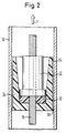
- FIG. 2 Another embodiment of the piston according to the invention is shown in FIG. 2. Components of this figure with the same function as components of Fig. 1 have the same reference numerals.
- the second piston part 14 of this embodiment is designed as a hollow cylinder.
- the first piston part 12 is arranged in the second piston part 14 and is dimensioned such that the outer diameter of the stop plate of the first piston part 12 is less than or equal to the inner diameter of the receptacle for the first piston part 12 in the second piston part 14.
- An elastomer plate 32 is arranged between the first piston part 12 and the second piston part 14 as a damping means.
- the first piston part 12, the second piston part 14 and the elastomer plate 32 are arranged one on top of the other. However, a spacing can also be provided.
- the second piston part 14 has a sealing lip 20, as has already been described with reference to FIG. 1, and which detaches from the system on the inner wall of the cylinder when heated in the manner described above.
- the side wall 34 of the second piston part 14 tapers towards the piston safety device (not shown here) of the belt tensioner.
- the second piston part 14 is arranged on the side of the first piston part 12 facing the gas generator.
- the tapering of the side walls of the second piston part 14 creates additional space laterally between the first piston part 12 and the second piston part 14. This has the advantage that the thermoplastic material of the second piston part 14 is moved inward when heated, for example in the event of a vehicle fire, and under the effect of the gas pressure generated in the event of a misfire, and that the gas generated can pass the second piston part 14 more easily.
- the gas escapes through the open piston catch, which eliminates the risk of explosion.
- an elastomer plate 32 inserted between the first piston part 12 and the second piston part 14 takes over the damping function described in relation to FIG. 1 in order to reduce stress peaks on the first piston part 12 during the pretensioning process.
- FIG. 3 shows a further embodiment of the invention, which enables inexpensive production, in particular of the second piston part 14.
- the second piston part 14 is longitudinally divided into two sections 14a, 14b. It preferably consists of two halves which are essentially symmetrical with respect to a plane running through the central axis of the pull cable 16. During assembly, these halves can be pressed on of the piston part 12 are clipped onto the pull cable 16 around the piston part 12 onto the pull cable 16, so that the first piston part 12 and the second piston part 14 form a unit.
- a sealing lip 20 and damping means are provided on the second piston part 14 of this embodiment, which have the same functions as described with reference to FIGS. 1 and 2.
- the damping means are designed as a deformable rod structure 25 which is arranged between an end plate 40 of the second piston part 14 provided with the sealing lip 20 and a stop plate 24 for the first piston part 12.
- FIG. 4 shows a cross section through the first piston part 12 and the second piston part 14.
- the configuration of the second piston part in two essentially symmetrical halves 14a and 14b can be clearly seen.
- FIGS. 5 to 7 show further embodiments of the second piston part 14, which can be used in particular in connection with the embodiment shown in FIG. 1.
- FIG. 5 shows the upper region of the second piston part 14, which has an annular elevation 22 similar to the elevation 18 of FIG. 1 on the side facing the first piston part 12. In contrast to the embodiment of FIG. 1, this annular elevation 22 is undercut on the inside of the ring. For the passage of the pull cable 16, a passage is formed in the middle of the piston part 14 of this and the following versions.
- FIG. 6 shows the stop plate 24 for the first piston part 12, which is connected via a rod structure 25 to the end face of the second piston part 14 facing the first piston part 12.
- FIG. 7 shows a hollow-cylindrical second piston part 14, on the end side of which facing the first piston part 12, individual, conical elevations 26 are formed.
- a sleeve 30 projecting into a recess 28 of the second piston part 14 is formed on the inside of the end wall of the second piston part 14 concentrically with the second piston part 14.
- FIGS. 5 to 7 All of the embodiments shown in FIGS. 5 to 7 according to the invention in relation to the direction of movement of the second piston part 14 at the Pretensioning process front area of the second piston part 14 serve as damping means for the impact of the second piston part 14 on the first piston part 12 during the pretensioning process.
- 5 dampens the impact of the second piston part 14 by elastic and plastic deformation, in that the annular elevation 22 is first plastically deformed and then the further region of the piston part 14 yields elastically.
- the embodiment of FIG. 6 dampens the impact by resiliently yielding the framework 25, and the embodiment of FIG. 7 dampens the impact of the second piston part 14 on the first piston part 12 essentially by plastic deformation of the front area of the second piston part 14 into the recess 28 in.
- polypropylene and polyamide or polyformaldehyde can be used as the thermoplastic material for the second piston element 14.
Landscapes
- Engineering & Computer Science (AREA)
- Mechanical Engineering (AREA)
- General Engineering & Computer Science (AREA)
- Automotive Seat Belt Assembly (AREA)
Applications Claiming Priority (2)
| Application Number | Priority Date | Filing Date | Title |
|---|---|---|---|
| DE9304152U DE9304152U1 (fr) | 1993-03-20 | 1993-03-20 | |
| DE9304152U | 1993-03-20 |
Publications (2)
| Publication Number | Publication Date |
|---|---|
| EP0616928A1 true EP0616928A1 (fr) | 1994-09-28 |
| EP0616928B1 EP0616928B1 (fr) | 1996-12-11 |
Family
ID=6890922
Family Applications (1)
| Application Number | Title | Priority Date | Filing Date |
|---|---|---|---|
| EP94103196A Expired - Lifetime EP0616928B1 (fr) | 1993-03-20 | 1994-03-03 | Tendeur de sangle pour ceintures de sécurité avec moteur pyrotechnique |
Country Status (5)
| Country | Link |
|---|---|
| US (1) | US5468019A (fr) |
| EP (1) | EP0616928B1 (fr) |
| JP (1) | JP2595194B2 (fr) |
| DE (2) | DE9304152U1 (fr) |
| ES (1) | ES2062968T3 (fr) |
Cited By (1)
| Publication number | Priority date | Publication date | Assignee | Title |
|---|---|---|---|---|
| EP0663326A1 (fr) * | 1994-01-18 | 1995-07-19 | TRW Occupant Restraint Systems GmbH | Dispositif d'attrapage d'un piston pour un entraînement linéaire pyrotechnique |
Families Citing this family (20)
| Publication number | Priority date | Publication date | Assignee | Title |
|---|---|---|---|---|
| DE9312135U1 (de) * | 1993-08-13 | 1994-06-01 | Leicher Gmbh & Co | Gurtstraffer |
| GB9601075D0 (en) * | 1996-01-19 | 1996-03-20 | Alliedsignal Ltd | Pretensioner |
| DE29609054U1 (de) * | 1996-05-20 | 1996-09-19 | Trw Repa Gmbh | Gurtstraffer für ein Fahrzeuginsassen-Rückhaltesystem |
| DE19638441A1 (de) * | 1996-09-19 | 1998-03-26 | Trw Repa Gmbh | Verfahren zum Herstellen von Preßteilen für Fahrzeuginsassen-Rückhaltesysteme |
| DE29612781U1 (de) * | 1996-07-23 | 1996-11-21 | Trw Repa Gmbh | Pyrotechnische Linearantriebseinrichtung für einen Gurtstraffer |
| GB2315985B (en) * | 1996-08-13 | 2000-11-22 | Alliedsignal Ltd | Pretensioner |
| DE29616414U1 (de) * | 1996-09-20 | 1997-01-23 | Trw Repa Gmbh | Gurtstraffer |
| DE29707352U1 (de) * | 1997-04-23 | 1997-08-21 | Trw Repa Gmbh | Straffer für einen Sicherheitsgurt |
| US6017060A (en) * | 1997-11-26 | 2000-01-25 | Trw Vehicle Safety Systems Inc. | Pressure relief plug |
| DE19927270C2 (de) | 1999-06-15 | 2002-07-11 | Breed Automotive Tech | Rückhaltevorrichtung für einen auf eine Gurtspule aufwickelbaren Sicherheitsgurt eines Kraftfahrzeugs |
| US6340176B1 (en) | 2000-03-31 | 2002-01-22 | Delphi Technologies, Inc. | Seat restraint tensioner |
| NL1019869C2 (nl) * | 2001-05-11 | 2002-11-12 | Whiplash Preventie Systems Hol | Pyrotechnische bedieningsinrichting en daarmee uitgeruste stoel, alsmede daarin toe te passen dempingsorgaan. |
| JP2003054360A (ja) * | 2001-06-06 | 2003-02-26 | Takata Corp | シートベルト装置 |
| DE102004009641A1 (de) * | 2004-02-27 | 2005-09-15 | Trw Automotive Gmbh | Linearantrieb zum Straffen eines Sicherheitsgurts |
| DE102005049659B3 (de) * | 2005-10-18 | 2007-04-05 | Autoliv Development Ab | Straffeinrichtung für Sicherheitsgurte mit einem oliveförmigen Kolben |
| JP2011063177A (ja) * | 2009-09-18 | 2011-03-31 | Tokai Rika Co Ltd | プリテンショナ |
| KR101371754B1 (ko) * | 2012-12-12 | 2014-03-07 | 현대자동차(주) | 차량용 시트벨트의 프리텐셔너 장치 |
| FR3017240B1 (fr) * | 2014-02-04 | 2016-01-29 | Ncs Pyrotechnie Et Tech Sas | Coupe-circuit pyrotechnique |
| DE102015010807A1 (de) * | 2015-08-21 | 2017-02-23 | Trw Automotive Gmbh | Gurtstraffer |
| US20190195310A1 (en) * | 2017-12-27 | 2019-06-27 | On Top Safety, Inc. | Force damper |
Citations (4)
| Publication number | Priority date | Publication date | Assignee | Title |
|---|---|---|---|---|
| FR2491340A1 (fr) * | 1980-10-06 | 1982-04-09 | Repa Feinstanzwerk Gmbh | Tendeur de rappel pour un enrouleur automatique de ceinture de securite |
| DE8406217U1 (de) * | 1984-02-29 | 1985-09-12 | Autoflug Gmbh, 2084 Rellingen | Gurtstraffer für einen selbstsperrenden Sicherheitsgurtaufroller |
| GB2217181A (en) * | 1988-03-22 | 1989-10-25 | Autoflug Gmbh | Drive means for safety belt tighteners |
| EP0558963A2 (fr) * | 1992-03-05 | 1993-09-08 | TRW Occupant Restraint Systems GmbH | Dispositif tendeur linéaire pour un système de retenue dans un véhicule |
Family Cites Families (6)
| Publication number | Priority date | Publication date | Assignee | Title |
|---|---|---|---|---|
| JPS49124731U (fr) * | 1973-02-22 | 1974-10-25 | ||
| DE3137263C2 (de) * | 1980-10-06 | 1985-12-19 | TRW Repa GmbH, 7071 Alfdorf | Zylinder/Kolben-Antrieb insbesondere für Rückstrammsysteme in Sicherheitsgurtwickelautomaten |
| DE3238710C2 (de) * | 1982-10-19 | 1986-10-23 | TRW Repa GmbH, 7077 Alfdorf | Antriebsvorrichtung mit in einem Zylinder pyrotechnisch angetriebenem Kolben |
| JPH0724295Y2 (ja) * | 1988-09-29 | 1995-06-05 | 本田技研工業株式会社 | シートベルトプリローダ装置のピストン構造 |
| ES2013985T3 (es) * | 1988-09-29 | 1994-01-16 | Trw Repa Gmbh | Dispositivo de accionamiento para sistemas de retencion en automoviles. |
| JPH075001Y2 (ja) * | 1988-09-29 | 1995-02-08 | 本田技研工業株式会社 | シートベルトプリローダ装置の取付け構造 |
-
1993
- 1993-03-20 DE DE9304152U patent/DE9304152U1/de not_active Expired - Lifetime
-
1994
- 1994-03-03 DE DE59401226T patent/DE59401226D1/de not_active Expired - Fee Related
- 1994-03-03 EP EP94103196A patent/EP0616928B1/fr not_active Expired - Lifetime
- 1994-03-03 ES ES94103196T patent/ES2062968T3/es not_active Expired - Lifetime
- 1994-03-14 US US08/213,193 patent/US5468019A/en not_active Expired - Fee Related
- 1994-03-18 JP JP6049087A patent/JP2595194B2/ja not_active Expired - Lifetime
Patent Citations (4)
| Publication number | Priority date | Publication date | Assignee | Title |
|---|---|---|---|---|
| FR2491340A1 (fr) * | 1980-10-06 | 1982-04-09 | Repa Feinstanzwerk Gmbh | Tendeur de rappel pour un enrouleur automatique de ceinture de securite |
| DE8406217U1 (de) * | 1984-02-29 | 1985-09-12 | Autoflug Gmbh, 2084 Rellingen | Gurtstraffer für einen selbstsperrenden Sicherheitsgurtaufroller |
| GB2217181A (en) * | 1988-03-22 | 1989-10-25 | Autoflug Gmbh | Drive means for safety belt tighteners |
| EP0558963A2 (fr) * | 1992-03-05 | 1993-09-08 | TRW Occupant Restraint Systems GmbH | Dispositif tendeur linéaire pour un système de retenue dans un véhicule |
Cited By (2)
| Publication number | Priority date | Publication date | Assignee | Title |
|---|---|---|---|---|
| EP0663326A1 (fr) * | 1994-01-18 | 1995-07-19 | TRW Occupant Restraint Systems GmbH | Dispositif d'attrapage d'un piston pour un entraînement linéaire pyrotechnique |
| US5495790A (en) * | 1994-01-18 | 1996-03-05 | Trw Repa Gmbh | Piston catcher for a pyrotechnic linear piston and cylinder drive |
Also Published As
| Publication number | Publication date |
|---|---|
| US5468019A (en) | 1995-11-21 |
| DE9304152U1 (fr) | 1993-05-13 |
| JPH0747922A (ja) | 1995-02-21 |
| EP0616928B1 (fr) | 1996-12-11 |
| ES2062968T1 (es) | 1995-01-01 |
| JP2595194B2 (ja) | 1997-03-26 |
| DE59401226D1 (de) | 1997-01-23 |
| ES2062968T3 (es) | 1997-04-16 |
Similar Documents
| Publication | Publication Date | Title |
|---|---|---|
| EP0616928B1 (fr) | Tendeur de sangle pour ceintures de sécurité avec moteur pyrotechnique | |
| DE19918596B4 (de) | Vorrichtung zum Straffen eines Sicherheitsgurtes | |
| DE102006002209B3 (de) | Aktuator | |
| EP0644089B1 (fr) | Dispositif d'actionnement | |
| EP0614789B1 (fr) | Prétendeur pour systèmes de ceinture de sécurité pour véhicules | |
| EP0558963B1 (fr) | Dispositif tendeur linéaire pour un système de retenue dans un véhicule | |
| EP1232916B1 (fr) | Prétensionneur de ceinture de sécurité | |
| DE2624942C2 (de) | Vorrichtung zum Spannen und gesteuerten Wiedernachgeben von Sicherheitsgurten | |
| EP0360902B1 (fr) | Dispositif propulsif pour des systèmes de retention dans des véhicules automobiles | |
| DE102006053563A1 (de) | Gurtstraffer für ein Sicherheitsgurtsystem | |
| DE4415373A1 (de) | Gasgenerator für ein Fahrzeug-Rückhaltesystem | |
| DE102006002435A1 (de) | Verfahren zur Herstellung eines Gasgenerators und mittels des Verfahrens hergestellter Gasgenerator | |
| EP0614790B1 (fr) | Prétendeur pour systèmes de ceinture de sécurité dans les véhicules | |
| WO2017005718A1 (fr) | Dispositif de pré-tensionnement comprenant un dispositif d'étanchéité | |
| DE2330635B2 (de) | Durch eine Treibladung betätigte Einstellvorrichtung | |
| DE102011013255A1 (de) | Entriegelungsvorrichtung | |
| DE4208157C2 (de) | Vorrichtung zum Straffen eines Sicherheitsgurtes in einem Kraftfahrzeug | |
| DE102008025399B4 (de) | Pyrotechnische Antriebseinheit | |
| DE102011106514A1 (de) | Pyrotechnischer Aktuator mit Entlüftung, Motorhaubenaufsteller und Gurtstraffer mit einem solchen Aktuator | |
| DE102018100605B3 (de) | Gurtstraffer mit gestuftem Rohrinnendurchmesser | |
| DE2411702A1 (de) | Kraftbegrenzer, der aus einem zylinder und einem kolben besteht | |
| DE102007034401A1 (de) | Gurtstraffer | |
| EP3427898A1 (fr) | Système de fixation pour au moins un raccord à vis | |
| DE102011014362A1 (de) | Linearantrieb für ein Fahrzeuginsassen-Rückhaltesystem | |
| WO2023102589A1 (fr) | Actionneur pyrotechnique |
Legal Events
| Date | Code | Title | Description |
|---|---|---|---|
| PUAI | Public reference made under article 153(3) epc to a published international application that has entered the european phase |
Free format text: ORIGINAL CODE: 0009012 |
|
| AK | Designated contracting states |
Kind code of ref document: A1 Designated state(s): DE ES FR GB IT SE |
|
| ITCL | It: translation for ep claims filed |
Representative=s name: DR. ING. A. RACHELI & C. |
|
| GBC | Gb: translation of claims filed (gb section 78(7)/1977) | ||
| EL | Fr: translation of claims filed | ||
| REG | Reference to a national code |
Ref country code: ES Ref legal event code: BA2A Ref document number: 2062968 Country of ref document: ES Kind code of ref document: T1 |
|
| 17P | Request for examination filed |
Effective date: 19941115 |
|
| 17Q | First examination report despatched |
Effective date: 19951114 |
|
| RAP1 | Party data changed (applicant data changed or rights of an application transferred) |
Owner name: TRW OCCUPANT RESTRAINT SYSTEMS GMBH |
|
| GRAG | Despatch of communication of intention to grant |
Free format text: ORIGINAL CODE: EPIDOS AGRA |
|
| GRAH | Despatch of communication of intention to grant a patent |
Free format text: ORIGINAL CODE: EPIDOS IGRA |
|
| GRAH | Despatch of communication of intention to grant a patent |
Free format text: ORIGINAL CODE: EPIDOS IGRA |
|
| GRAA | (expected) grant |
Free format text: ORIGINAL CODE: 0009210 |
|
| PGFP | Annual fee paid to national office [announced via postgrant information from national office to epo] |
Ref country code: SE Payment date: 19961206 Year of fee payment: 4 |
|
| AK | Designated contracting states |
Kind code of ref document: B1 Designated state(s): DE ES FR GB IT SE |
|
| ITF | It: translation for a ep patent filed |
Owner name: DR. ING. A. RACHELI & C. |
|
| REF | Corresponds to: |
Ref document number: 59401226 Country of ref document: DE Date of ref document: 19970123 |
|
| ET | Fr: translation filed | ||
| GBT | Gb: translation of ep patent filed (gb section 77(6)(a)/1977) |
Effective date: 19970211 |
|
| REG | Reference to a national code |
Ref country code: ES Ref legal event code: FG2A Ref document number: 2062968 Country of ref document: ES Kind code of ref document: T3 |
|
| PLBE | No opposition filed within time limit |
Free format text: ORIGINAL CODE: 0009261 |
|
| STAA | Information on the status of an ep patent application or granted ep patent |
Free format text: STATUS: NO OPPOSITION FILED WITHIN TIME LIMIT |
|
| 26N | No opposition filed | ||
| PG25 | Lapsed in a contracting state [announced via postgrant information from national office to epo] |
Ref country code: SE Free format text: LAPSE BECAUSE OF NON-PAYMENT OF DUE FEES Effective date: 19980304 |
|
| EUG | Se: european patent has lapsed |
Ref document number: 94103196.5 |
|
| REG | Reference to a national code |
Ref country code: GB Ref legal event code: IF02 |
|
| PGFP | Annual fee paid to national office [announced via postgrant information from national office to epo] |
Ref country code: GB Payment date: 20020205 Year of fee payment: 9 |
|
| PG25 | Lapsed in a contracting state [announced via postgrant information from national office to epo] |
Ref country code: GB Free format text: LAPSE BECAUSE OF NON-PAYMENT OF DUE FEES Effective date: 20030303 |
|
| PGFP | Annual fee paid to national office [announced via postgrant information from national office to epo] |
Ref country code: FR Payment date: 20030303 Year of fee payment: 10 |
|
| GBPC | Gb: european patent ceased through non-payment of renewal fee | ||
| PGFP | Annual fee paid to national office [announced via postgrant information from national office to epo] |
Ref country code: ES Payment date: 20040322 Year of fee payment: 11 |
|
| PG25 | Lapsed in a contracting state [announced via postgrant information from national office to epo] |
Ref country code: FR Free format text: LAPSE BECAUSE OF NON-PAYMENT OF DUE FEES Effective date: 20041130 |
|
| REG | Reference to a national code |
Ref country code: FR Ref legal event code: ST |
|
| PG25 | Lapsed in a contracting state [announced via postgrant information from national office to epo] |
Ref country code: IT Free format text: LAPSE BECAUSE OF NON-PAYMENT OF DUE FEES;WARNING: LAPSES OF ITALIAN PATENTS WITH EFFECTIVE DATE BEFORE 2007 MAY HAVE OCCURRED AT ANY TIME BEFORE 2007. THE CORRECT EFFECTIVE DATE MAY BE DIFFERENT FROM THE ONE RECORDED. Effective date: 20050303 |
|
| PG25 | Lapsed in a contracting state [announced via postgrant information from national office to epo] |
Ref country code: ES Free format text: LAPSE BECAUSE OF NON-PAYMENT OF DUE FEES Effective date: 20050304 |
|
| PGFP | Annual fee paid to national office [announced via postgrant information from national office to epo] |
Ref country code: DE Payment date: 20050331 Year of fee payment: 12 |
|
| REG | Reference to a national code |
Ref country code: ES Ref legal event code: FD2A Effective date: 20050304 |
|
| PG25 | Lapsed in a contracting state [announced via postgrant information from national office to epo] |
Ref country code: DE Free format text: LAPSE BECAUSE OF NON-PAYMENT OF DUE FEES Effective date: 20061003 |