EP0555935B1 - Etagère de conteneur du distribution - Google Patents
Etagère de conteneur du distribution Download PDFInfo
- Publication number
- EP0555935B1 EP0555935B1 EP93200400A EP93200400A EP0555935B1 EP 0555935 B1 EP0555935 B1 EP 0555935B1 EP 93200400 A EP93200400 A EP 93200400A EP 93200400 A EP93200400 A EP 93200400A EP 0555935 B1 EP0555935 B1 EP 0555935B1
- Authority
- EP
- European Patent Office
- Prior art keywords
- basket
- rack
- take
- rod
- rails
- Prior art date
- Legal status (The legal status is an assumption and is not a legal conclusion. Google has not performed a legal analysis and makes no representation as to the accuracy of the status listed.)
- Expired - Lifetime
Links
Images


Classifications
-
- A—HUMAN NECESSITIES
- A47—FURNITURE; DOMESTIC ARTICLES OR APPLIANCES; COFFEE MILLS; SPICE MILLS; SUCTION CLEANERS IN GENERAL
- A47F—SPECIAL FURNITURE, FITTINGS, OR ACCESSORIES FOR SHOPS, STOREHOUSES, BARS, RESTAURANTS OR THE LIKE; PAYING COUNTERS
- A47F5/00—Show stands, hangers, or shelves characterised by their constructional features
- A47F5/0081—Show stands or display racks with movable parts
- A47F5/0093—Show stands or display racks with movable parts movable in a substantially horizontal direction
-
- A—HUMAN NECESSITIES
- A47—FURNITURE; DOMESTIC ARTICLES OR APPLIANCES; COFFEE MILLS; SPICE MILLS; SUCTION CLEANERS IN GENERAL
- A47F—SPECIAL FURNITURE, FITTINGS, OR ACCESSORIES FOR SHOPS, STOREHOUSES, BARS, RESTAURANTS OR THE LIKE; PAYING COUNTERS
- A47F1/00—Racks for dispensing merchandise; Containers for dispensing merchandise
- A47F1/04—Racks or containers with arrangements for dispensing articles, e.g. by means of gravity or springs
Definitions
- the invention relates to a rack having take-out baskets or similar display/take-out containers for merchandise in a retail business, in particular a self-service shop.
- Known display/take-out shelves for merchandise items such as nuts packed in bags or pouches, or fragile merchandise items packed under inclusion of air, such as crisps and the like, are often baskets made from bar grating material, either in shallow drawer form or in the form of a deep box having a filling opening at the top and an inclined bottom, with a take-out opening provided in the front wall at the bottom end facing the consumer.
- first-in, first-out only those merchandise items are accessible to the consumer that were first placed into the basket, and the other merchandise items present in the basket are protected against undesired manipulation and damage.
- Shallow drawer-shaped baskets are usually arranged one closely below the other and it is desired that they can be pulled out in turns so that they can be filled.
- the take-out portion is still within the consumer's reach, however, it is desired that the basket can temporarily be moved to a lower level so that it can be filled.
- known take-out baskets are suspended from a tilting lever system via which a basket can be moved in upright position between the high level and the low level.
- German Gebrauchsmuster 8515351 discloses a rack comprising shallow display/take-out containers having inclined bottoms, which, via a rail construction, are slidably extendible and retractable on opposite sides in inclined supports extending from rack columns, wherein stopping means are present for limiting the lower, extended position, while the upper, retracted position can be fixed by a lock operable from the front of the container, and wherein tension springs are provided between the front side of the container and the rack.
- a drawback of this known apparatus is that the tension springs and the lock are arranged under the flat bottom in the central portion of the basket, which may impede the shifting of the merchandise over the bottom of a subjacent container.
- the object of the invention is to provide a rack having display/take-out containers of the type described, having a displacement construction which is simple and takes up little space, not requiring any complicated tilting lever systems which take up much space, and wherein the above-mentioned drawback of the construction disclosed in the Gebrauchsmuster is avoided.
- the assemblies of the rails and rods can be supplemented with a tension spring, which, according to the invention, is likewise arranged in the space below a wall forming a transition between the bottom and a side wall.
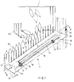
- a basket produced from bar grating material is mounted on columns of a display rack by means of a guide assembly 4 which is parallel to the inclined basket bottom 3.
- the guide assembly is accommodated in spaces 5 located below inclined walls 6 which form a transition between the bottom 3 and upright side walls 7 of the basket.
- the guide assembly 4 comprises rails 8, known per se, of which a stationary portion 9 is connected to the rack 2 and a movable part 10 is connected to the basket 1 via a section 11. Mounted on section 11 are laterally projecting supports 12, wherein a rod 14 is journalled so as to be rotatable about its axis. Rod 14 carries stopping means in the form of lugs 15.
- a section 16, connected to the stationary portion 9 of the rails or directly to the rack 2, comprises stopping means in the form of bent-out lugs 17, the rotation of rod 14, which comprises an end hook 14a for gripping, allowing stopping lugs 15 of the rod to be swung between a downward position as shown in Figures 1 and 2, wherein stopping lugs 17 of section 16 prevent rod 14 from moving and thereby prevent basket 1 from moving downwards, and a horizontal position, in which rod 14 and consequently also the basket are capable of moving downwards. This downward movement is limited by lug 15 at the rear end of rod 14 abutting against lug 17 at the front end of section 16.
- a tube 18 is mounted on support 12 at the end of guide means 4 by a screw 19.
- Accommodated in tube 18 is a helical spring 20 having its rear end mounted on the column 2 at 21.
- basket 1 is provided with an awning-shaped top front wall 22. Between this wall 22 and a low bottom front wall 23, the products offered for sale, schematically indicated in the drawing as bags 24 with food, are within the consumer's reach.
- the awning-shaped top front wall is dimensioned such that a stock of bags 24 is stored at the top of basket 1 and bags 24 slide on automatically as a single layer over basket bottom 3 upon removal of the foremost bags lying on the bottom.
- rod 14 is gripped at the end hook 14a and rotated over 90° such that downwardly extending stopping lugs 15 are swung laterally and move beyond the reach of stopping lugs 17 which are stationarily connected to the fixed portion of the rack.
- the basket can be lowered while being guided, a part of the weight of the basket and the contents thereof being taken up by spring 20.
- rod 14 is rotated reversely, the abutment of rear lug 15 against lug 17 prevents further downward movement and via these lugs the weight of the basket is taken up in the stationary portion of the apparatus.
- Figures 4 and 5 show an alternative manner of mounting a take-out basket, which may be of the type discussed with reference to Figures 1-3, on a display rack having parallel columns 2.
- a supporting beam 25, extending along the bottom edge of the rear wall of the basket, is used for the connection between a rack column and the stationary rail portion 9 or any other portion that is also connected to a take-out basket.
- Supporting beam 25 comprises two telescopic tube sections 26, 27, of rectangular design in the embodiment shown, at the free ends thereof provided with hooks 28, through which the supporting beam and the take-out basket mounted thereon can be suspended from two rack columns 2. Because the two supporting beam portions 26, 27 are telescopic, being for instance extensible by about 3 centimetres, small deviations from the intended distance between two successive rack columns can be compensated.
- a push element 29 is shown that can be used advantageously in a take-out basket of the type set forth in the present application, particularly so when the basket has a bottom of grating bars inclined towards the take-out end.
- this pre-load can be realized by gravity or by using a push or pull spring of the helical spring type.
- Such helical springs take up space in the bottom zone of a basket. Further, a helical spring, in released condition, has a considerable length in relation to the effective spring travel. Consequently, if a push element is to be loaded throughout its path along the bottom, the helical spring must not be arranged in front of or behind the push element in its bottom path, but beside or below the push element. In that case, the spring force must be transmitted to the push element via a wire or the like and a bend pulley.
- the push element 29 is pre-loaded by a spring in the form of a self-coiling helical spring 31.
- this spring takes up very little space and can be mounted directly between the push element 29 and a fixed point at the basket bottom 3 so as to be operative in the bottom surface.
- helical spring 31 is accommodated in push element 29 and fixed at the front edge of the basket bottom at a beam 32.
- helical spring 31 hardly takes up any space and hence does not form any obstacle to packages 24 present in a basket or in a subjacent basket.
- end hooks 14a of rods 14 at the take-out side of baskets 1 can be covered by caps 33, indicated in Figure 1.
- caps 33 indicated in Figure 1.
Claims (5)
- Etagère munie de paniers à extraire ou de récipients à extraire/présentoirs similaires pour des marchandises dans un magasin de détail, en particulier un self-service, dans laquelle au moins un panier (1) est construit comme un récipient en forme de tiroir ou de boîte possédant un fond incliné (3), les marchandises (24) présentes dans le panier (1) étant accessibles au consommateur à l'extrémité du fond tournée vers le consommateur et le panier (1) pouvant être déplacé le long de rails (8, 9) disposés sur les parties latérales du panier (1) entre une position supérieure dans laquelle la paroi postérieure du panier est située entre les colonnes de montage d'une étagère (2) et une position de remplissage du fond dans laquelle le panier (1) est situé à l'avant de l'étagère (2) et arrêté par des moyens de butée (15, 17), caractérisée en ce que, de chaque côté du panier (1), dans un espace (5) sous une paroi inclinée (6) formant une transition entre le fond (3) et une paroi latérale (7), un ensemble formé des rails (8, 9) et d'une tige (14), montée sur tourillon à rotation en parallèle à la construction de rails, est raccordé au panier (1), les moyens de butée (15, 17) étant disposés sur la tige (14) et sur les rails (8, 9) et les moyens de butée (15) de la tige (14), par rotation de la tige (14), pouvant être amenés à coopérer avec les moyens de butée (17) des rails (8, 9) pour définir les positions supérieure et inférieure respectives du panier (1).
- Etagère selon la revendication 1 dans laquelle des ressorts de rappel (20) sont raccordés, à une extrémité, au panier (1) et, à l'autre extrémité, à la colonne de l'étagère (2), caractérisée en ce que, pour chacun des ensembles des rails (8, 9) et d'une tige (14), un ressort de rappel (20) est disposé dans ledit espace (5).
- Etagère selon l'une des revendications 1 ou 2, caractérisée en ce que, pour la fixation entre une colonne d'étagère (2) et la partie fixe du rail (9) ou toute autre partie également raccordée au panier à extraire, est utilisé un profilé de support (25) s'étendant le long du bord du fond de la paroi postérieure du panier (1) et comprenant deux sections en tubes télescopiques (26, 27), ledit faisceau de support (25) étant doté à ses extrémité de crochets (28) permettant au profilé de support (25) et au panier à extraire (1) qui est fixé sur celui-ci d'être suspendus à deux colonnes de l'étagère (2).
- Etagère selon l'une quelconque des revendications précédentes, dans laquelle des éléments poussoirs (29) sont capables de coulisser sur le fond du panier (3) au-dessus des barres de fond (30) et des moyens à ressort (31) sont présents pour pousser des rangées de marchandises emballées (24) vers le côté d'extraction du panier (1), caractérisée en ce que les moyens à ressort sont formés par un ressort hélicoïdal à boudin (31), monté directement entre l'élément poussoir (29) et un point fixe (32) sur le bord frontal du fond du panier (3) de manière à être opérationnel sur la surface du fond (3).
- Etagère selon l'une quelconque des revendications précédentes, caractérisée en ce que le crochet d'extrémité (14a) de la tige (14) faisant partie du dispositif de verrouillage du panier est recouvert par un cache (33).
Applications Claiming Priority (2)
| Application Number | Priority Date | Filing Date | Title |
|---|---|---|---|
| NL9200278A NL9200278A (nl) | 1992-02-14 | 1992-02-14 | Uitneemkorfstelling. |
| NL9200278 | 1992-02-14 |
Publications (2)
| Publication Number | Publication Date |
|---|---|
| EP0555935A1 EP0555935A1 (fr) | 1993-08-18 |
| EP0555935B1 true EP0555935B1 (fr) | 1996-06-12 |
Family
ID=19860437
Family Applications (1)
| Application Number | Title | Priority Date | Filing Date |
|---|---|---|---|
| EP93200400A Expired - Lifetime EP0555935B1 (fr) | 1992-02-14 | 1993-02-12 | Etagère de conteneur du distribution |
Country Status (3)
| Country | Link |
|---|---|
| EP (1) | EP0555935B1 (fr) |
| DE (1) | DE69303046D1 (fr) |
| NL (1) | NL9200278A (fr) |
Families Citing this family (25)
| Publication number | Priority date | Publication date | Assignee | Title |
|---|---|---|---|---|
| NL9301698A (nl) * | 1993-10-01 | 1995-05-01 | Hessels Metaalindustrie B V | Uittrekbaar draadschappenpresentatierek. |
| NL9400249A (nl) * | 1994-02-18 | 1995-10-02 | Adriaan Teunissen | Uitschuifbare steunorganen voor een schap. |
| GB2319954B (en) * | 1996-12-09 | 2000-11-29 | Kleenkut Invest Ltd | A ramp |
| US9173504B2 (en) | 2005-09-12 | 2015-11-03 | Rtc Industries, Inc. | Product management display system |
| US8967394B2 (en) | 2005-09-12 | 2015-03-03 | Rtc Industries, Inc. | Product management display system with trackless pusher mechanism |
| US11259652B2 (en) | 2005-09-12 | 2022-03-01 | Rtc Industries, Inc. | Product management display system |
| US8739984B2 (en) | 2005-09-12 | 2014-06-03 | Rtc Industries, Inc. | Product management display system with trackless pusher mechanism |
| US11344138B2 (en) | 2005-09-12 | 2022-05-31 | Rtc Industries, Inc. | Product management display system |
| US10285510B2 (en) | 2005-09-12 | 2019-05-14 | Rtc Industries, Inc. | Product management display system |
| US9486088B2 (en) | 2005-09-12 | 2016-11-08 | Rtc Industries, Inc. | Product management display system |
| US9265362B2 (en) | 2005-09-12 | 2016-02-23 | RTC Industries, Incorporated | Product management display system |
| US9138075B2 (en) | 2005-09-12 | 2015-09-22 | Rtc Industries, Inc. | Product management display system |
| US9265358B2 (en) | 2005-09-12 | 2016-02-23 | RTC Industries, Incorporated | Product management display system |
| US8978904B2 (en) | 2005-09-12 | 2015-03-17 | Rtc Industries, Inc. | Product management display system with trackless pusher mechanism |
| US10952546B2 (en) | 2005-09-12 | 2021-03-23 | Rtc Industries, Inc. | Product management display system with trackless pusher mechanism |
| US9232864B2 (en) | 2005-09-12 | 2016-01-12 | RTC Industries, Incorporated | Product management display system with trackless pusher mechanism |
| US9060624B2 (en) | 2005-09-12 | 2015-06-23 | Rtc Industries, Inc. | Product management display system with rail mounting clip |
| US9259102B2 (en) | 2005-09-12 | 2016-02-16 | RTC Industries, Incorporated | Product management display system with trackless pusher mechanism |
| US11583109B2 (en) | 2005-09-12 | 2023-02-21 | Rtc Industries, Inc. | Product management display system with trackless pusher mechanism |
| US9750354B2 (en) | 2005-09-12 | 2017-09-05 | Rtc Industries, Inc. | Product management display system |
| DE102014209110A1 (de) | 2014-05-14 | 2015-11-19 | Gebr. Willach Gmbh | Schrägfachbodenregal |
| US9955802B2 (en) | 2015-04-08 | 2018-05-01 | Fasteners For Retail, Inc. | Divider with selectively securable track assembly |
| US10178909B2 (en) | 2016-01-13 | 2019-01-15 | Rtc Industries, Inc. | Anti-splay device for merchandise display system |
| AU2018285708B2 (en) | 2017-06-16 | 2021-06-24 | Rtc Industries, Inc. | Product management display system with trackless pusher mechanism |
| CN113044504B (zh) * | 2021-03-10 | 2022-08-05 | 李建波 | 一种轨道外卖箱的自动配送方法及系统 |
Family Cites Families (5)
| Publication number | Priority date | Publication date | Assignee | Title |
|---|---|---|---|---|
| US3471209A (en) * | 1967-08-15 | 1969-10-07 | Howard Displays Inc | Display cabinet |
| FR2412290A1 (fr) * | 1977-12-26 | 1979-07-20 | Gen Alimentaire | Presentoir a compartiments longitudinaux inclines formant glissieres pour les articles exposes |
| DE8515351U1 (de) * | 1985-05-24 | 1985-07-04 | EFEKA Friedrich & Kaufmann GmbH & Co KG, 4800 Bielefeld | Schubkastenregal |
| US5197610A (en) * | 1987-06-24 | 1993-03-30 | Leggett & Platt, Incorporated | Display rack |
| US5026129A (en) * | 1990-02-07 | 1991-06-25 | Marlboro Marketing, Inc. | Merchandise display assembly |
-
1992
- 1992-02-14 NL NL9200278A patent/NL9200278A/nl unknown
-
1993
- 1993-02-12 EP EP93200400A patent/EP0555935B1/fr not_active Expired - Lifetime
- 1993-02-12 DE DE69303046T patent/DE69303046D1/de not_active Expired - Lifetime
Also Published As
| Publication number | Publication date |
|---|---|
| NL9200278A (nl) | 1993-09-01 |
| EP0555935A1 (fr) | 1993-08-18 |
| DE69303046D1 (de) | 1996-07-18 |
Similar Documents
| Publication | Publication Date | Title |
|---|---|---|
| EP0555935B1 (fr) | Etagère de conteneur du distribution | |
| US5306077A (en) | Drawer unit for displaying and dispensing of merchandise | |
| US8662320B2 (en) | Theft deterrent system for product display device | |
| US5435582A (en) | Shopping cart | |
| US6830157B2 (en) | Pie pusher merchandising display device | |
| US4369887A (en) | Merchandizing rack | |
| CA2768030C (fr) | Procede et appareil de prelevement d?un emballage d'un systeme de distribution | |
| EP0437894B1 (fr) | Entrepôt à ajustage automatique | |
| US20120255924A1 (en) | Display tray and bar, and mounting bracket therefor | |
| US5265893A (en) | Grocery cart shelf | |
| US3643808A (en) | Gravity feed merchandising rack | |
| US4191296A (en) | Article dispensing rack | |
| EP0441452B1 (fr) | Assemblage extensible d'embase d'étagère pour gondoles de présentation | |
| US5240124A (en) | Storage cart | |
| US20090159546A1 (en) | Shelf and merchandise display system | |
| US5026129A (en) | Merchandise display assembly | |
| US6193067B1 (en) | Self-fronting merchandise display box | |
| US4102458A (en) | Device in racks for sales packages and the like | |
| US4602570A (en) | Extendable shelf for a display rack | |
| US4220245A (en) | Wine rack | |
| US3464748A (en) | Tape display case | |
| US4938492A (en) | Shopping trolley of the nestable type comprising a rack which is capable of withdrawal beneath its carrier basket | |
| EP1724732B1 (fr) | Etagère pour machine de vente de produits | |
| US3270891A (en) | Display rack with recovery means | |
| EP0875187A2 (fr) | Dispositif de présentation de produits |
Legal Events
| Date | Code | Title | Description |
|---|---|---|---|
| PUAI | Public reference made under article 153(3) epc to a published international application that has entered the european phase |
Free format text: ORIGINAL CODE: 0009012 |
|
| AK | Designated contracting states |
Kind code of ref document: A1 Designated state(s): BE DE DK ES FR GB IT NL PT SE |
|
| 17P | Request for examination filed |
Effective date: 19940215 |
|
| 17Q | First examination report despatched |
Effective date: 19950717 |
|
| GRAH | Despatch of communication of intention to grant a patent |
Free format text: ORIGINAL CODE: EPIDOS IGRA |
|
| GRAA | (expected) grant |
Free format text: ORIGINAL CODE: 0009210 |
|
| AK | Designated contracting states |
Kind code of ref document: B1 Designated state(s): BE DE DK ES FR GB IT NL PT SE |
|
| PG25 | Lapsed in a contracting state [announced via postgrant information from national office to epo] |
Ref country code: IT Free format text: LAPSE BECAUSE OF FAILURE TO SUBMIT A TRANSLATION OF THE DESCRIPTION OR TO PAY THE FEE WITHIN THE PRE;WARNING: LAPSES OF ITALIAN PATENTS WITH EFFECTIVE DATE BEFORE 2007 MAY HAVE OCCURRED AT ANY TIME BEFORE 2007. THE CORRECT EFFECTIVE DATE MAY BE DIFFERENT FROM THE ONE RECORDED.SCRIBED TIME-LIMIT Effective date: 19960612 Ref country code: FR Effective date: 19960612 Ref country code: ES Free format text: THE PATENT HAS BEEN ANNULLED BY A DECISION OF A NATIONAL AUTHORITY Effective date: 19960612 Ref country code: DK Effective date: 19960612 |
|
| REF | Corresponds to: |
Ref document number: 69303046 Country of ref document: DE Date of ref document: 19960718 |
|
| PG25 | Lapsed in a contracting state [announced via postgrant information from national office to epo] |
Ref country code: SE Effective date: 19960912 Ref country code: PT Effective date: 19960912 |
|
| PG25 | Lapsed in a contracting state [announced via postgrant information from national office to epo] |
Ref country code: DE Effective date: 19960913 |
|
| EN | Fr: translation not filed | ||
| PG25 | Lapsed in a contracting state [announced via postgrant information from national office to epo] |
Ref country code: GB Effective date: 19970212 |
|
| PLBE | No opposition filed within time limit |
Free format text: ORIGINAL CODE: 0009261 |
|
| STAA | Information on the status of an ep patent application or granted ep patent |
Free format text: STATUS: NO OPPOSITION FILED WITHIN TIME LIMIT |
|
| 26N | No opposition filed | ||
| GBPC | Gb: european patent ceased through non-payment of renewal fee |
Effective date: 19970212 |
|
| PGFP | Annual fee paid to national office [announced via postgrant information from national office to epo] |
Ref country code: NL Payment date: 20030228 Year of fee payment: 11 |
|
| PGFP | Annual fee paid to national office [announced via postgrant information from national office to epo] |
Ref country code: BE Payment date: 20030311 Year of fee payment: 11 |
|
| PG25 | Lapsed in a contracting state [announced via postgrant information from national office to epo] |
Ref country code: BE Free format text: LAPSE BECAUSE OF NON-PAYMENT OF DUE FEES Effective date: 20040228 |
|
| BERE | Be: lapsed |
Owner name: *SARA LEE/DE N.V. Effective date: 20040228 |
|
| PG25 | Lapsed in a contracting state [announced via postgrant information from national office to epo] |
Ref country code: NL Free format text: LAPSE BECAUSE OF NON-PAYMENT OF DUE FEES Effective date: 20040901 |
|
| NLV4 | Nl: lapsed or anulled due to non-payment of the annual fee |
Effective date: 20040901 |