EP0441452B1 - Assemblage extensible d'embase d'étagère pour gondoles de présentation - Google Patents
Assemblage extensible d'embase d'étagère pour gondoles de présentation Download PDFInfo
- Publication number
- EP0441452B1 EP0441452B1 EP91200254A EP91200254A EP0441452B1 EP 0441452 B1 EP0441452 B1 EP 0441452B1 EP 91200254 A EP91200254 A EP 91200254A EP 91200254 A EP91200254 A EP 91200254A EP 0441452 B1 EP0441452 B1 EP 0441452B1
- Authority
- EP
- European Patent Office
- Prior art keywords
- shelf assembly
- extension
- base shelf
- shelf
- support surface
- Prior art date
- Legal status (The legal status is an assumption and is not a legal conclusion. Google has not performed a legal analysis and makes no representation as to the accuracy of the status listed.)
- Expired - Lifetime
Links
Images
Classifications
-
- A—HUMAN NECESSITIES
- A47—FURNITURE; DOMESTIC ARTICLES OR APPLIANCES; COFFEE MILLS; SPICE MILLS; SUCTION CLEANERS IN GENERAL
- A47F—SPECIAL FURNITURE, FITTINGS, OR ACCESSORIES FOR SHOPS, STOREHOUSES, BARS, RESTAURANTS OR THE LIKE; PAYING COUNTERS
- A47F5/00—Show stands, hangers, or shelves characterised by their constructional features
- A47F5/0081—Show stands or display racks with movable parts
- A47F5/0093—Show stands or display racks with movable parts movable in a substantially horizontal direction
-
- A—HUMAN NECESSITIES
- A47—FURNITURE; DOMESTIC ARTICLES OR APPLIANCES; COFFEE MILLS; SPICE MILLS; SUCTION CLEANERS IN GENERAL
- A47F—SPECIAL FURNITURE, FITTINGS, OR ACCESSORIES FOR SHOPS, STOREHOUSES, BARS, RESTAURANTS OR THE LIKE; PAYING COUNTERS
- A47F5/00—Show stands, hangers, or shelves characterised by their constructional features
- A47F5/10—Adjustable or foldable or dismountable display stands
- A47F5/101—Display racks with slotted uprights
- A47F5/103—Display shelving racks with the uprights aligned in only one plane
Definitions
- This invention relates generally to a merchandise display device for supporting merchandise thereon, and more particularly concerns an expandable base shelf assembly for use with gondolas as conventionally used in supermarkets for display of merchandise.
- Shelves of this kind are already known e.g. from US-A-4 776 472.
- Traditional store shelving, or as it is called, gondola shelving is designed to arrange a product in a horizontal format.
- Existing store shelving includes metal shelves, hooking onto vertical uprights, known as standards, that have a series of punched slots in which hooks, attached to the metal shelves, are engaged. This is similar to conventional wall type bookshelves.
- the shelves extend perpendicularly from the back wall of the gondola and are adjustable vertically in steps within the range of approximately 2 to 2 1/2 inches per step depending upon the vertical spacing of the punched slots in the standards.
- the conventional shelves have a depth which ranges from approximately 16 to 26 inches.
- coffee can be displayed in an aisle along a length of an aisle that averages anywhere from 8 feet to 40 feet.
- shopability becomes more and more difficult.
- the inconvenience in shopping a particular brand of product is greater when the product is displayed horizontally as compared to a vertical format.
- a typical six foot high gondola is set up conventionally with six to seven shelves.
- the thickness of the shelves per se takes up space that could be used for product and also, there must be a space underneath each shelf that is necessary to remove the product on the shelf below.
- This "wasted" space increases as the number of shelves increase.
- the shelves of extra depth remain until the merchandise is replaced even though they are substantially unloaded.
- What is needed is a shelving arrangement that provides more space in a gondola for merchandise and allows for variation in depth of the merchandise display.
- Another object of this invention is to provide shelving assembly that eliminates most of the waste space inherent in using conventional gondola shelving.
- Yet another object of this invention is to provide an improved shelving assembly that allows a vertical presentation of product and reduces the aisle length of the required display.
- the shelving in accordance with the invention for supporting merchandise, includes a sloping base shelf that extends outwardly from the gondola rear wall surface slightly upwardly toward the shopping aisle.
- the base shelf is supported by hollow tubes or channels that rest upon the floor.
- An extension shelf is mounted on a framework of hollow tubes that are slidably mounted to the floor channels of the base shelf.
- the extension shelf also slopes upwardly at approximately the same angle as the base shelf.
- a pin on the frame of the extension shelf is selectably positioned in any of a plurality of stop positions provided on the base shelf framework. In a first position the base shelf overlies the extension shelf and in a second position the extension shelf extends beyond the base shelf into the aisle.
- the shelves, although substantially parallel, are not coplanar and a vertical gap, that increases as the assembly extends, separates the two support surfaces.
- the base shelf surface is supplemented by pulling out the extension shelf from beneath the base shelf to any one of a plurality of positions depending on the quantity of additional shelf space desired.
- the extension shelf can remain in such extended position until the merchandise is removed or sold, after which the extension shelf may be readily retracted by disengaging the pin from the stop position on the base shelf framework.
- a grid of spaced rods extends perpendicularly from the sloping base shelf until it contacts the back wall of the gondola.
- a sloping surface is provided against which the product leans while standing on the sloped base shelf. Because the sloped support surface tilts the product toward the gondola wall, high stacking is possible without the conventional intermediate shelves.
- a boxed product is less likely to fall forward when it is initially tilted back. Therefore, more product may be stacked vertically and remain stable.
- a guard rail at the front, that is, facing the aisle, of the extension shelf protects the merchandise from shoppers carts and assures that merchandise does not fall into the aisle.
- the expandable base shelf assembly is conveniently positioned between a pair of adjacent uprights on a gondola although a greater length along the aisle can be provided.
- the conventional horizontal gondola shelves are eliminated so that a fully packed vertically oriented display, without interruption, can be provided.
- additional adjustable shelves may be added along the vertical height of the gondola uprights for special promotional effects or to handle a particular category of product in the same brand as displayed on the expandable base shelf assembly.
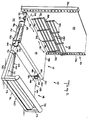
- An expandable base shelf assembly 10 includes a base shelf assembly 12 and an extension shelf assembly 14 that are intended for use with a conventional shopping market gondola 16.
- the base shelf assembly 12 includes a planar support surface 18 having an outer downturned apron 20 and an inner downturned apron 22.
- the lower edge of the inner apron 22 is intended to rest upon the floor 32 or other base of the gondola 16 with the planar surface of the apron 22 pressing against the back wall 24 of the gondola.
- the base shelf assembly 12 fits between a pair of vertical uprights or standards 26 of the gondola.
- the lateral edges 28 of the support surface 18 are supported by a bent wire strut 30, which makes two contacts with the support surface 18 and two contacts with the floor 32.
- the strut 30 supports the surface 18 at a upward angle relative to the back wall 24 of the gondola such that the included angle 34 between them is less than 90°.
- a pair of U-shaped channels 36 are connected to the underside of the planar support surface 18 and add rigidity thereto.
- Another U-shaped channel 38 is located beneath the planar support surface 18 close to the inner apron 22. The channel 38 is positioned in alignment with a plurality of holes 40 that are formed through the planar support surface 18 for purposes described more fully hereinafter.
- Channels 42 each having a flat surface 44 for resting on the floor 32, are fixedly attached to a bent wire strut 30 connected on each side of the support surface 18.
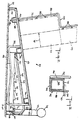
- the outer arm 46 of the channel 42 is rectangular and the inner arm 48 includes a plurality of regularly spaced ramps or sawteeth 50.
- the sawteeth 50 extend above the level of the rectangular outer arm 46 (Fig. 2).
- Each tooth includes a ramp 52 sloping upward toward the outer apron 20 with a substantially perpendicular trailing edge 54 between each tooth.
- a notch 56 is formed in the inner arm 48 outward of the most forward tooth 50, with the perpendicular edge 54 of that tooth 50 forming one side of the notch 56.
- the extension shelf assembly 14 includes at each side a pair of rectangular tubes 58, only one of which is visible in the drawings.
- the tubes 58 are connected by an intermediate cross tube 60 that provides rigidity to the structure.
- Each tube 58 slides in a channel 42 between the outer arm 46 and inner arm 48.
- a planar extension surface 62 is attached to the base structure 58, 60 at the inner ends of the tubes 58, and to the cross tube 60 at the outer end of the planar surface 62.
- a frame or bent rod 64 supports the planar surface 62 from beneath near each lateral edge 66, and is bent to a vertical orientation. The end of the rod enters an opening 68 in the top surface of the front piece 60 (Fig. 2). At the rear, the rod 64 is bent down vertically and connected to the tube 58.
- the planar extension surface 62 is at an angle such that the support surface 62 is substantially parallel to the planar support surface 18.
- a handle 74 is connected by vertical and posts 75 to the rectangular tubes 58. This handle 74 extends above the sloped planar surfaces 18, 62 and serves many functions.
- the handle 74 is the grip that a person uses in extending the extension shelf assembly 14 from beneath the base shelf assembly 12.
- the handle 74 also acts as a retainer rail to help keep the product from falling into the aisle where shoppers are walking, and the handle 74 acts as a guardrail to protect the product from accidental impacts by shopping carts as they move up and down the aisles.
- a locking pin 70 is connected to the top surface 72 of each rectangular tube 58 and extends inwardly beneath the planar surface 62 such that when the tubes 58 are respectively telescoped within the channels 42, the pins 70 are positioned on the top edge of the inner arm 48 near the inner end of the plurality of sawteeth 50 on the inner arm 48.
- the locking pin 70 makes contact with the ramp 52 of the first inner tooth 50, slides up the ramp 52 and drops at the perpendicular trailing edge 54 to the base of the next tooth.
- the locking pins 70 rides up the ramp 52 of the next adjacent tooth 50 until it passes the perpendicular trailing edge 54 of that tooth and drops to the base of the next tooth.
- the extension shelf assembly 14 is easily pulled out, by gripping the handle 74, to any desired extension in increments based upon the periodic spacing of the teeth 50.
- the pin 70 moves past the perpendicular edge 54 of the outermost tooth 50, the pin 70 falls into a notch 56 and further pulling in the outward direction does not further displace the extension shelf assembly 14.
- the extension shelf assembly 14 is pivoted around the edge 76 acting as a fulcrum by grasping the handle 74 and swinging it in a outward and downward arc.
- the rear ends of the tubes 58 are lifted from the base of the channels 42 until the pin 70 is disengaged from the notch 56 or is elevated above the apex on any tooth 50.
- the extension shelf assembly 14 is pushed back to its desired position, including the fully retracted position.
- the length of the tooth ramp 52 approximately equals the depth 79 of the package 77.
- a vertical gap opens progressively between the lower edge of the front apron 20 on the base shelf assembly 12 and the sloped planar support surface 62 of the extension shelf assembly 14.
- Product 77 (not shown) when placed on the sloped extension shelf surface 62 is supported from the rear by leaning against the apron 20.
- product stacking stability is provided by the tiered relationship of the substantially parallel, but separated, surfaces 18, 62.
- the gap or step between the two support surfaces increases with the increased degree of extension so as to accommodate a greater loading of product with stability.
- a grid assembly 78 includes a plurality of transverse rods 80 having substantially the same length as the planar support surface 18.
- the rods 80 are connected together in two tiers by means of support rods 82 that are spaced at the longitudinal ends of the transverse rods 80 and at intermediate locations to give rigidity to the structure.
- a step or offset 84 in the support rods 82 sets a portion of the transverse rods 80 in a plane spaced from, but parallel to the plane of the remaining rods 80.
- These support rods 82 have extensions 86 beyond the first transverse rod 80 and the extensions 86 pass through the holes 40 in the planar support surface 18. As best illustrated in Fig.
- the ends or extensions 86 pass through the base 88 of the channel 38 beneath the support surface 18 such that a cantilever type connection is provided between the grid assembly 78 and the base shelf assembly 12.
- the support rods 82 extend away from the support surface 18, substantially at a right angle thereto.
- the offset 84 is positioned on the grid assembly 78 such that an integral number (1, 2, 3.%) of product packages 77, stacked on top of one another, facing the front of the unit, fit against the grid assembly 78 in the space between the planar support surface 18 and the offset 84.
- an arrangement of shelves is provided which is extendable as required for the product and for particular promotions, such as sales.
- the extension can readily be reduced as product is sold so as to produce less interference in the aisle.
- Conventional shelving is entirely eliminated such that the space that shelves conventionally fill is now available for product. Good visibility is provided for the product, even when only a few packages remain, because the conventional shelves are not present to obstruct the view and the product tilts back for better viewing. Because there is no need for intermediate shelving, a vertical display format is feasible.
Landscapes
- Display Racks (AREA)
- Assembled Shelves (AREA)
- Forklifts And Lifting Vehicles (AREA)
- Freezers Or Refrigerated Showcases (AREA)
- Warehouses Or Storage Devices (AREA)
- Supports Or Holders For Household Use (AREA)
Claims (8)
- Assemblage extensible d'embase d'étagère (10) à utiliser avec une surface verticale (24) et une surface horizontale (32) pour supporter un produit d'exposition, comprenant:
un assemblage d'embase d'étagère (12) reposant sur ladite surface horizontale (32), ledit assemblage (12) comprenant une première surface de support (18) en surélévation au-dessus de ladite surface horizontale (32), ladite première surface de support (18) ayant une extrémité intérieure (22) destinée à être adjacente à ladite surface verticale (24) et une extrémité extérieure (20), et un premier moyen de support (42) pour s'engager avec ladite surface horizontale (18) et pour maintenir ladite première surface de support (18) dans ladite position surélevée;
un assemblage d'étagère d'extension (14) comprenant une deuxième surface de support (62) en surélévation au-dessus de ladite surface horizontale (32), ledit assemblage d'étagère d'extension (14) étant mobile d'un bout à l'autre de ladite première surface de support entre une première position où essentiellement toute la deuxième surface de support (62) est en dessous de ladite première surface de support (18) ayant un intervalle verticale entre elles deux, et une deuxième position où ladite deuxième surface de support (62) s'étend essentiellement au-delà de ladite extrémité extérieure (20) de ladite première surface de support (18), lesdites première et deuxième surfaces de support (18, 62) se trouvant dans des plans différents, ledit intervalle augmentant lorsque l'extension dudit assemblage d'étagère d'extension(14)augmente, et un deuxième moyen de support (58) pour s'engager avec ledit premier moyen de support (42) et pour maintenir ladite deuxième surface de support (62) dans ladite position surélevée; et
un moyen de positionnement faisant s'engager l'un l'autre ledit assemblage d'embase d'étagère (12) et ledit assemblage d'étagère d'extension (14) pour maintenir librement ladite deuxième surface de support (62) dans une position choisie entre lesdites première et deuxième positions et dans des positions intermédiaires. - Assemblage extensible d'embase d'étagère (10) selon la revendication 1, dans lequel lesdites première et deuxième surfaces de support (18, 62) sont maintenues sensiblement parallèles l'une à l'autre.
- Assemblage extensible d'embase d'étagère (10) selon la revendication 2, dans lequel lesdites surfaces de support (18, 62) sont courbées vers le haut dans la direction allant de ladite extrémité intérieure (22) à ladite extrémité extérieure (20) de ladite surface de support.
- Assemblage d'embase d'étagère (10) selon la revendication 1, dans lequel ledit deuxième moyen de support (58) dudit assemblage d'étagère d'extension (14) s'engage en coulissant avec ledit premier moyen de support (42) dudit assemblage d'embase d'étagère.
- Assemblage extensible d'embase d'étagère (10) selon la revendication 1, dans lequel ledit moyen de positionnement comprend un moyen formant goujon (70) se trouvant sur ledit assemblage d'étagère d'extension (14) et un moyen en dents de scie (50) se trouvant sur ledit assemblage d'étagère d'extension, la position dudit assemblage d'étagère d'extension(14)par rapport audit assemblage d'embase d'étagère (12) étant établie par l'engagement dudit moyen formant goujon (70) avec ledit moyen en dents de scie (50).
- Assemblage extensible d'embase d'étagère (10) selon la revendication 5, dans lequel ledit moyen formant goujon est un goujon (70) se trouvant sur ledit assemblage d'étagère d'extension (14), ledit goujon s'étendant à angle droit par rapport à la direction d'extension de l'étagère, et ledit moyen en dents de scie (50) comprend une succession de rampes (52) inclinées vers le haut, de ladite extrémité intérieure (22) à ladite extrémité extérieure (20), les flancs arrière (54) desdites rampes étant essentiellement à angle droit par rapport à ladite surface horizontale quand ledit assemblage extensible d'embase d'étagère (12) repose sur ladite surface horizontale, ledit goujon (70) coulissant sur ledit profil en dents de scie lorsque ladite étagère à coulisse se déplace de ladite première position à ladite deuxième position, lesdits flancs arrière (54) s'engageant avec ledit goujon (70), bloquant le mouvement de retour dudit assemblage d'étagère d'extension (12), lesdites rampes (52) résistant au mouvement dans la direction extérieure.
- Assemblage extensible d'embase d'étagère (10) selon la revendication 6, dans lequel les longueurs desdites rampes (52) correspondent à la profondeur de l'emballage du produit (77) qui doit être empilé verticalement sur ledit assemblage d'embase d'étagère (12).
- Assemblage extensible d'embase d'étagère (10) selon la revendication 1, et comprenant en outre une barre reliée audit assemblage d'étagère d'extension à son extrémité extérieure (20), ladite barre étant placée au-delà de l'extrémité extérieure de ladite première surface de support et surélevée de façon à être plus haute que ladite première surface de support, ladite barre servant de poignée (74) pour changer les positions relatives entre ledit assemblage d'embase d'étagère (12) et ledit assemblage d'étagère d'extension (14), et servant de protection pour les produits stockés sur ledit assemblage extensible d'embase d'étagère.
Applications Claiming Priority (2)
| Application Number | Priority Date | Filing Date | Title |
|---|---|---|---|
| US477059 | 1990-02-07 | ||
| US07/477,059 US5096074A (en) | 1990-02-07 | 1990-02-07 | Expandable base shelf assembly for display gondolas |
Publications (2)
| Publication Number | Publication Date |
|---|---|
| EP0441452A1 EP0441452A1 (fr) | 1991-08-14 |
| EP0441452B1 true EP0441452B1 (fr) | 1994-08-10 |
Family
ID=23894351
Family Applications (1)
| Application Number | Title | Priority Date | Filing Date |
|---|---|---|---|
| EP91200254A Expired - Lifetime EP0441452B1 (fr) | 1990-02-07 | 1991-02-07 | Assemblage extensible d'embase d'étagère pour gondoles de présentation |
Country Status (10)
| Country | Link |
|---|---|
| US (1) | US5096074A (fr) |
| EP (1) | EP0441452B1 (fr) |
| AT (1) | ATE109637T1 (fr) |
| AU (1) | AU7027191A (fr) |
| DE (1) | DE69103291T2 (fr) |
| DK (1) | DK0441452T3 (fr) |
| ES (1) | ES2062659T3 (fr) |
| IE (1) | IE910411A1 (fr) |
| NO (1) | NO910475L (fr) |
| PT (1) | PT96696A (fr) |
Families Citing this family (22)
| Publication number | Priority date | Publication date | Assignee | Title |
|---|---|---|---|---|
| US5205421A (en) * | 1991-04-01 | 1993-04-27 | Leggett & Platt, Incorporated | Gondola display rack |
| US5314080A (en) * | 1992-12-28 | 1994-05-24 | Wentworth Richard W | Adjustable display rack |
| FR2700457B1 (fr) * | 1993-01-21 | 1995-04-07 | Norauto Sa | Gondole à embase modulaire. |
| US6161708A (en) * | 1997-10-23 | 2000-12-19 | Darko Company, Inc. | Merchandising display system having laterally and longitudinally adjustable compartments |
| US6454369B1 (en) * | 1999-05-04 | 2002-09-24 | Accuride International, Inc. | Pull-out keyboard tray |
| US6267258B1 (en) | 1999-05-07 | 2001-07-31 | Gilmour, Inc. | Gravity feed pull out shelf with rear storage area and associated method for displaying and storing a product |
| GB2368000A (en) * | 2000-10-12 | 2002-04-24 | Oakley Young Associates Ltd | Shelf mounted goods display device |
| US7568583B2 (en) * | 2001-07-16 | 2009-08-04 | Maytag Corporation | Upright rear wall extension for refrigerator shelves |
| FR2861272B1 (fr) * | 2003-10-23 | 2006-02-03 | Dior Christian Parfums | Console pour la presentation de produits |
| US20050189311A1 (en) * | 2004-02-27 | 2005-09-01 | Colby John W. | Display |
| JP2006124154A (ja) * | 2004-09-29 | 2006-05-18 | Toshiba Tec Corp | 用紙後処理装置 |
| WO2006072036A1 (fr) * | 2004-12-29 | 2006-07-06 | Rock-Tenn Shared Services, Llc | Dispositif présentoir pour marchandises au détail |
| GB0509801D0 (en) * | 2005-05-13 | 2005-06-22 | Cadbury Schweppes Plc | Merchandising/display element |
| US20060278782A1 (en) * | 2005-05-31 | 2006-12-14 | Lockwood Thomas A | Display system |
| US20090178988A1 (en) * | 2008-01-16 | 2009-07-16 | Lang Thomas F | Expandable display system |
| US8292095B2 (en) | 2009-04-29 | 2012-10-23 | Rock-Tenn Shared Services, Llc | Expandable display system |
| US20110284485A1 (en) * | 2010-05-21 | 2011-11-24 | Sparkowski Robert P | Adjustable shelving display |
| US9420902B2 (en) * | 2014-02-19 | 2016-08-23 | Nestec S.A. | Shelf wedge for displaying products on an existing shelf system |
| ES2662450T3 (es) * | 2014-07-09 | 2018-04-06 | Hmy Group | Dispositivo de estanterías que comprende una estantería inferior móvil para exponer artículos |
| USD790267S1 (en) | 2015-02-18 | 2017-06-27 | Big Skies Limited | Pull-out shelf unit |
| DE202016102313U1 (de) * | 2016-05-02 | 2016-05-22 | Lidl Stiftung & Co. Kg | Waren-Präsentations-Möbel |
| US11266256B2 (en) | 2019-12-17 | 2022-03-08 | Walmart Apollo, Llc | Expendable service surface device |
Family Cites Families (9)
| Publication number | Priority date | Publication date | Assignee | Title |
|---|---|---|---|---|
| US2953244A (en) * | 1958-04-30 | 1960-09-20 | Curtis A Phillips | Adjustable display and storage device |
| DE1303175B (de) * | 1966-04-23 | 1971-07-01 | Hettlage Kg | Rahmen fuer zerlegbare Regale, Kabinen, Kaesten u. dgl. |
| DE1781008B1 (de) * | 1968-08-08 | 1972-05-31 | Erhard Fickert | Regal mit uebereinander angeordneten Faechern,die von gleich weit frei vorragenden Tragarmen gebildet sind |
| DE1911331A1 (de) * | 1969-03-06 | 1970-10-01 | Felix Zock | Fachboden,insbesondere fuer Stufenregale |
| US3685687A (en) * | 1970-08-12 | 1972-08-22 | Plastics Inc | Horizontally stackable tray |
| US3894634A (en) * | 1971-03-19 | 1975-07-15 | Unex Conveying Systems Inc | Display and delivery stand |
| US4602570A (en) * | 1982-06-01 | 1986-07-29 | Frito-Lay, Inc. | Extendable shelf for a display rack |
| US4540222A (en) * | 1983-02-28 | 1985-09-10 | Burrell Alfred A | Cabinet structure for storing, displaying and indexing |
| US4776472A (en) * | 1987-10-09 | 1988-10-11 | Brand Manufacturing Corp. | Bakery display shelves |
-
1990
- 1990-02-07 US US07/477,059 patent/US5096074A/en not_active Expired - Lifetime
-
1991
- 1991-02-06 AU AU70271/91A patent/AU7027191A/en not_active Abandoned
- 1991-02-07 ES ES91200254T patent/ES2062659T3/es not_active Expired - Lifetime
- 1991-02-07 AT AT91200254T patent/ATE109637T1/de not_active IP Right Cessation
- 1991-02-07 PT PT96696A patent/PT96696A/pt not_active Application Discontinuation
- 1991-02-07 NO NO91910475A patent/NO910475L/no unknown
- 1991-02-07 EP EP91200254A patent/EP0441452B1/fr not_active Expired - Lifetime
- 1991-02-07 DE DE69103291T patent/DE69103291T2/de not_active Expired - Fee Related
- 1991-02-07 DK DK91200254.0T patent/DK0441452T3/da active
- 1991-02-07 IE IE041191A patent/IE910411A1/en unknown
Also Published As
| Publication number | Publication date |
|---|---|
| NO910475L (no) | 1991-08-08 |
| ES2062659T3 (es) | 1994-12-16 |
| DE69103291D1 (de) | 1994-09-15 |
| ATE109637T1 (de) | 1994-08-15 |
| US5096074A (en) | 1992-03-17 |
| PT96696A (pt) | 1992-12-31 |
| DK0441452T3 (da) | 1994-09-26 |
| NO910475D0 (no) | 1991-02-07 |
| EP0441452A1 (fr) | 1991-08-14 |
| IE910411A1 (en) | 1991-08-14 |
| DE69103291T2 (de) | 1994-12-01 |
| AU7027191A (en) | 1991-08-08 |
Similar Documents
| Publication | Publication Date | Title |
|---|---|---|
| EP0441452B1 (fr) | Assemblage extensible d'embase d'étagère pour gondoles de présentation | |
| AU2004275525B2 (en) | Stand for displaying articles, such as flat-packed articles | |
| US5197610A (en) | Display rack | |
| US9038833B2 (en) | Telescoping display rack | |
| CA2698061C (fr) | Systeme integre de gestion d'affection de rayon | |
| US4809855A (en) | Display rack | |
| EP3007593B1 (fr) | Système de marchandisation comprenant ensemble de poussoir | |
| US5992653A (en) | Display and dispensing pack | |
| US8851303B2 (en) | Integrated shelf allocation management system | |
| US20100032392A1 (en) | Shelf bottle pusher system | |
| US20090039040A1 (en) | Product Display System for Packaged Products and Method of Use Thereof | |
| US20120006771A1 (en) | Product merchandising system for walk-in display coolers and the like | |
| US20070138116A1 (en) | Adjustable shelving system | |
| US20160324334A1 (en) | Merchandising system with pusher assembly | |
| CA2309918A1 (fr) | Presentoir autoporteur | |
| US6799689B2 (en) | Shelving display rack | |
| US6193067B1 (en) | Self-fronting merchandise display box | |
| US5921414A (en) | Double sided display rack | |
| US6837387B2 (en) | Modular product display | |
| WO2001045537A1 (fr) | Ensemble presentoir | |
| EP0032122A2 (fr) | Etagère à distribution par gravité | |
| US5791500A (en) | Inclined display rack | |
| CA2453273C (fr) | Presentoir de rayonnage | |
| WO2013012709A1 (fr) | Système manuel de gestion d'étagère qui est peu encombrant | |
| IES61969B2 (en) | Counter display/storage system |
Legal Events
| Date | Code | Title | Description |
|---|---|---|---|
| PUAI | Public reference made under article 153(3) epc to a published international application that has entered the european phase |
Free format text: ORIGINAL CODE: 0009012 |
|
| AK | Designated contracting states |
Kind code of ref document: A1 Designated state(s): AT BE CH DE DK ES FR GB GR IT LI LU NL SE |
|
| 17P | Request for examination filed |
Effective date: 19920204 |
|
| 17Q | First examination report despatched |
Effective date: 19931001 |
|
| GRAA | (expected) grant |
Free format text: ORIGINAL CODE: 0009210 |
|
| AK | Designated contracting states |
Kind code of ref document: B1 Designated state(s): AT BE CH DE DK ES FR GB GR IT LI LU NL SE |
|
| PG25 | Lapsed in a contracting state [announced via postgrant information from national office to epo] |
Ref country code: IT Free format text: LAPSE BECAUSE OF FAILURE TO SUBMIT A TRANSLATION OF THE DESCRIPTION OR TO PAY THE FEE WITHIN THE PRE;WARNING: LAPSES OF ITALIAN PATENTS WITH EFFECTIVE DATE BEFORE 2007 MAY HAVE OCCURRED AT ANY TIME BEFORE 2007. THE CORRECT EFFECTIVE DATE MAY BE DIFFERENT FROM THE ONE RECORDED.SCRIBED TIME-LIMIT Effective date: 19940810 Ref country code: GR Free format text: LAPSE BECAUSE OF FAILURE TO SUBMIT A TRANSLATION OF THE DESCRIPTION OR TO PAY THE FEE WITHIN THE PRESCRIBED TIME-LIMIT Effective date: 19940810 Ref country code: LI Effective date: 19940810 Ref country code: AT Effective date: 19940810 Ref country code: CH Effective date: 19940810 |
|
| REF | Corresponds to: |
Ref document number: 109637 Country of ref document: AT Date of ref document: 19940815 Kind code of ref document: T |
|
| REF | Corresponds to: |
Ref document number: 69103291 Country of ref document: DE Date of ref document: 19940915 |
|
| REG | Reference to a national code |
Ref country code: DK Ref legal event code: T3 |
|
| REG | Reference to a national code |
Ref country code: CH Ref legal event code: PL |
|
| ET | Fr: translation filed | ||
| REG | Reference to a national code |
Ref country code: ES Ref legal event code: FG2A Ref document number: 2062659 Country of ref document: ES Kind code of ref document: T3 |
|
| EAL | Se: european patent in force in sweden |
Ref document number: 91200254.0 |
|
| PG25 | Lapsed in a contracting state [announced via postgrant information from national office to epo] |
Ref country code: LU Free format text: LAPSE BECAUSE OF NON-PAYMENT OF DUE FEES Effective date: 19950228 |
|
| PLBE | No opposition filed within time limit |
Free format text: ORIGINAL CODE: 0009261 |
|
| STAA | Information on the status of an ep patent application or granted ep patent |
Free format text: STATUS: NO OPPOSITION FILED WITHIN TIME LIMIT |
|
| 26N | No opposition filed | ||
| REG | Reference to a national code |
Ref country code: GB Ref legal event code: IF02 |
|
| PGFP | Annual fee paid to national office [announced via postgrant information from national office to epo] |
Ref country code: DK Payment date: 20040123 Year of fee payment: 14 |
|
| PGFP | Annual fee paid to national office [announced via postgrant information from national office to epo] |
Ref country code: GB Payment date: 20040204 Year of fee payment: 14 |
|
| PGFP | Annual fee paid to national office [announced via postgrant information from national office to epo] |
Ref country code: SE Payment date: 20040216 Year of fee payment: 14 Ref country code: NL Payment date: 20040216 Year of fee payment: 14 |
|
| PGFP | Annual fee paid to national office [announced via postgrant information from national office to epo] |
Ref country code: FR Payment date: 20040227 Year of fee payment: 14 Ref country code: ES Payment date: 20040227 Year of fee payment: 14 |
|
| PGFP | Annual fee paid to national office [announced via postgrant information from national office to epo] |
Ref country code: BE Payment date: 20040323 Year of fee payment: 14 |
|
| PGFP | Annual fee paid to national office [announced via postgrant information from national office to epo] |
Ref country code: DE Payment date: 20040417 Year of fee payment: 14 |
|
| PG25 | Lapsed in a contracting state [announced via postgrant information from national office to epo] |
Ref country code: GB Free format text: LAPSE BECAUSE OF NON-PAYMENT OF DUE FEES Effective date: 20050207 |
|
| PG25 | Lapsed in a contracting state [announced via postgrant information from national office to epo] |
Ref country code: ES Free format text: LAPSE BECAUSE OF NON-PAYMENT OF DUE FEES Effective date: 20050208 Ref country code: SE Free format text: LAPSE BECAUSE OF NON-PAYMENT OF DUE FEES Effective date: 20050208 |
|
| PG25 | Lapsed in a contracting state [announced via postgrant information from national office to epo] |
Ref country code: DK Free format text: LAPSE BECAUSE OF NON-PAYMENT OF DUE FEES Effective date: 20050228 Ref country code: BE Free format text: LAPSE BECAUSE OF NON-PAYMENT OF DUE FEES Effective date: 20050228 |
|
| BERE | Be: lapsed |
Owner name: *SARA LEE/DE N.V. Effective date: 20050228 |
|
| PG25 | Lapsed in a contracting state [announced via postgrant information from national office to epo] |
Ref country code: DE Free format text: LAPSE BECAUSE OF NON-PAYMENT OF DUE FEES Effective date: 20050901 Ref country code: NL Free format text: LAPSE BECAUSE OF NON-PAYMENT OF DUE FEES Effective date: 20050901 |
|
| GBPC | Gb: european patent ceased through non-payment of renewal fee |
Effective date: 20050207 |
|
| REG | Reference to a national code |
Ref country code: DK Ref legal event code: EBP |
|
| EUG | Se: european patent has lapsed | ||
| PG25 | Lapsed in a contracting state [announced via postgrant information from national office to epo] |
Ref country code: FR Free format text: LAPSE BECAUSE OF NON-PAYMENT OF DUE FEES Effective date: 20051031 |
|
| NLV4 | Nl: lapsed or anulled due to non-payment of the annual fee |
Effective date: 20050901 |
|
| REG | Reference to a national code |
Ref country code: FR Ref legal event code: ST Effective date: 20051031 |
|
| REG | Reference to a national code |
Ref country code: ES Ref legal event code: FD2A Effective date: 20050208 |
|
| BERE | Be: lapsed |
Owner name: *SARA LEE/DE N.V. Effective date: 20050228 |