EP0555543B1 - Kondensatabscheider - Google Patents
Kondensatabscheider Download PDFInfo
- Publication number
- EP0555543B1 EP0555543B1 EP92121130A EP92121130A EP0555543B1 EP 0555543 B1 EP0555543 B1 EP 0555543B1 EP 92121130 A EP92121130 A EP 92121130A EP 92121130 A EP92121130 A EP 92121130A EP 0555543 B1 EP0555543 B1 EP 0555543B1
- Authority
- EP
- European Patent Office
- Prior art keywords
- condensate
- housing
- sump
- gas cooler
- separator
- Prior art date
- Legal status (The legal status is an assumption and is not a legal conclusion. Google has not performed a legal analysis and makes no representation as to the accuracy of the status listed.)
- Expired - Lifetime
Links
- 230000006835 compression Effects 0.000 claims abstract description 10
- 238000007906 compression Methods 0.000 claims abstract description 10
- 238000012806 monitoring device Methods 0.000 claims abstract description 5
- 239000000428 dust Substances 0.000 claims description 4
- 239000004071 soot Substances 0.000 claims description 4
- 239000007789 gas Substances 0.000 abstract description 38
- 230000000694 effects Effects 0.000 abstract description 3
- 239000002912 waste gas Substances 0.000 abstract 3
- 238000001816 cooling Methods 0.000 description 9
- 239000000523 sample Substances 0.000 description 7
- 238000005259 measurement Methods 0.000 description 4
- 229920003043 Cellulose fiber Polymers 0.000 description 2
- 238000002485 combustion reaction Methods 0.000 description 2
- 239000002826 coolant Substances 0.000 description 2
- 239000000463 material Substances 0.000 description 2
- 238000012544 monitoring process Methods 0.000 description 2
- 238000012545 processing Methods 0.000 description 2
- 229920000742 Cotton Polymers 0.000 description 1
- 238000010521 absorption reaction Methods 0.000 description 1
- 229920002678 cellulose Polymers 0.000 description 1
- 239000001913 cellulose Substances 0.000 description 1
- 238000010276 construction Methods 0.000 description 1
- 239000000356 contaminant Substances 0.000 description 1
- 238000011161 development Methods 0.000 description 1
- 230000018109 developmental process Effects 0.000 description 1
- 238000001035 drying Methods 0.000 description 1
- 238000009413 insulation Methods 0.000 description 1
- 230000007774 longterm Effects 0.000 description 1
- 238000000034 method Methods 0.000 description 1
- 239000002245 particle Substances 0.000 description 1
- 230000035515 penetration Effects 0.000 description 1
- 238000005070 sampling Methods 0.000 description 1
- 229920006395 saturated elastomer Polymers 0.000 description 1
- XLYOFNOQVPJJNP-UHFFFAOYSA-N water Substances O XLYOFNOQVPJJNP-UHFFFAOYSA-N 0.000 description 1
Images
Classifications
-
- G—PHYSICS
- G01—MEASURING; TESTING
- G01N—INVESTIGATING OR ANALYSING MATERIALS BY DETERMINING THEIR CHEMICAL OR PHYSICAL PROPERTIES
- G01N1/00—Sampling; Preparing specimens for investigation
- G01N1/02—Devices for withdrawing samples
- G01N1/22—Devices for withdrawing samples in the gaseous state
- G01N1/2247—Sampling from a flowing stream of gas
- G01N1/2258—Sampling from a flowing stream of gas in a stack or chimney
-
- F—MECHANICAL ENGINEERING; LIGHTING; HEATING; WEAPONS; BLASTING
- F28—HEAT EXCHANGE IN GENERAL
- F28B—STEAM OR VAPOUR CONDENSERS
- F28B11/00—Controlling arrangements with features specially adapted for condensers
-
- G—PHYSICS
- G01—MEASURING; TESTING
- G01N—INVESTIGATING OR ANALYSING MATERIALS BY DETERMINING THEIR CHEMICAL OR PHYSICAL PROPERTIES
- G01N1/00—Sampling; Preparing specimens for investigation
- G01N1/28—Preparing specimens for investigation including physical details of (bio-)chemical methods covered elsewhere, e.g. G01N33/50, C12Q
- G01N1/42—Low-temperature sample treatment, e.g. cryofixation
-
- G—PHYSICS
- G01—MEASURING; TESTING
- G01N—INVESTIGATING OR ANALYSING MATERIALS BY DETERMINING THEIR CHEMICAL OR PHYSICAL PROPERTIES
- G01N1/00—Sampling; Preparing specimens for investigation
- G01N1/02—Devices for withdrawing samples
- G01N1/22—Devices for withdrawing samples in the gaseous state
- G01N2001/2282—Devices for withdrawing samples in the gaseous state with cooling means
-
- G—PHYSICS
- G01—MEASURING; TESTING
- G01N—INVESTIGATING OR ANALYSING MATERIALS BY DETERMINING THEIR CHEMICAL OR PHYSICAL PROPERTIES
- G01N1/00—Sampling; Preparing specimens for investigation
- G01N1/28—Preparing specimens for investigation including physical details of (bio-)chemical methods covered elsewhere, e.g. G01N33/50, C12Q
- G01N1/40—Concentrating samples
- G01N1/4022—Concentrating samples by thermal techniques; Phase changes
- G01N2001/4033—Concentrating samples by thermal techniques; Phase changes sample concentrated on a cold spot, e.g. condensation or distillation
Definitions
- the invention relates to a condensate separator, to which the exhaust gas to be analyzed is supplied and which is provided with a housing in which a gas cooler and a monitoring device are arranged, which responds when condensate separated from the exhaust gas reaches a selectable fill level in the housing.
- measuring devices with electrochemical sensors are used (exhaust gas measuring device “ECOM-S” from the applicant, described and shown in its brochure leaflet “ECOM ANALYSIS-COMPUTER”).
- ECOM-S exhaust gas measuring device
- condensate traps - also called condensate traps or water separators gas processing device "ECOM-K” from the applicant, loc. Cit.).
- ECOM-K gas processing device
- the exhaust gas is fed to a heat exchanger which is connected to a cooling element and is otherwise surrounded by thermal insulation.
- the cooling element on the other hand, is connected to a cooling body having ribs. The speed of the cooling air flowing past the fins is increased by a fan. Integrated monitoring signals when the condensate must be removed from the condensate separator.
- the known condensate separator is part of a measuring case, which must not assume an inclined position during the measurement, so that the measurement is not falsified, and which is designed to be complex.
- a narrow gas inlet bore in a cylindrical housing leads laterally downwards at right angles into a first, relatively greatly expanded space.
- the space is tapered downwards and designed with a tubular extension that ends above the bottom of an overflow vessel.
- Other rooms are arranged one after the other above the room and are separated from each other by sloping floor surfaces.
- the upper boundary of the last room forms a plate made of pressed filter material, after penetration of which the sample gas leads to the measuring system via an outlet.
- a cooler for sample gas processing for operational analyzes (DE 81 27 581 U1), in which a heat sink with internal cooling bottoms is provided, each having a bore.
- the heat sink is connected to a sample gas sampling probe on the side of the sample gas inlet via a flange.
- the heat sink On the opposite side, the heat sink carries a sample gas line as the sample outlet.
- the heat sink is surrounded by an outer jacket with coolant inlet, coolant outlet and thermometer socket.
- the invention is based on the object of designing a condensate separator in such a way that it can be installed / used in a position-neutral manner and is otherwise of simplified construction.
- this object is achieved according to the invention in that, in the hollow-cylindrical housing following an end face through which the exhaust gas to be analyzed enters, a condensate sump absorbing the separated condensate, which counteracts the saturation with condensate the effect of a compression spring is movable in the axial direction of the housing, and the monitoring device is provided between the condensate sump and a selectable measuring point at a distance from the end face.
- the condensate sump used in the invention consists of cellulose fibers which are compressed under high pressure. - Cellulose in this form is known as cotton wool -.
- the condensate sump makes the condensate separator independent of the position.
- the condensate sump increases its volume against the original pressing direction of the cellulose fibers and the effect of the compression spring regardless of the inclined position of the condensate separator.
- the exhaust gas separator which is preferably provided on the front sides with connecting sleeves for supplying and removing the exhaust gas, is a handy device which can be used in the inflow of any measuring devices for measuring the exhaust gases from combustion systems.
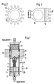
- the condensate separator chosen as an exemplary embodiment has a cylindrical housing 1.
- the end faces of the housing 1 are closed by a cover 2, 3.
- a grommet is formed on each cover 2, 3, via which a hose (not shown) for the supply of the exhaust gas to be measured and for its discharge or supply to the measuring device (also not shown) is applied.
- a condensate sump 4 is provided in the housing 1.
- the condensate sump 4 has its smallest volume in the dry state, its largest volume when it is saturated with a condensate.
- the compression spring 5 rests on the one hand via a disk 6 on the condensate sump 4, on the other hand it engages in a cylindrical cavity which is provided on the facing side of a cone 7.
- the compression spring 5 is designed as a helical spring, which is placed between the cone 7 and the disk 6 around a tube 8.
- the tube 8 is on the one hand in connection with the grommet on the cover 2, passes through the condensate sump 4 and the space between the condensate sump 4 and the cone 7, and on the other hand is further connected to an axial bore in the cone 7.
- a gas cooler 10 is fastened to the housing 1 by a narrow gap separated from the cone 7.
- the gas cooler 10 has a negative cone 11, which receives the cone 7.
- the edge of the negative cone 11 is angled to the outside in a flange-like manner and forms a screen 12 between the cone 7 and the wall of the housing 1.
- the part of the gas cooler projecting outside the wall of the housing 1 is either with cooling ribs 13 - FIG. 2 - or with a Peltier element 14, to which cooling fins 15 are connected on the side facing away from the housing 1 - FIG. 3 -.
- the gas cooler 10 In the interior of the housing 1, the gas cooler 10 is penetrated by an axial bore 16.
- a soot and dust filter 17 is arranged between the gas cooler 10 and the cover 3.
- moisture is excreted in the form of a condensate, which collects on the screen 12 and thence along the inner wall of the housing 1 reaches or drips onto the condensate sump 4.
- Measuring electrodes 20, 21 are provided between the gas cooler 10, preferably on its end face facing the cover 2, and a selectable location in the housing 1.
- the measuring electrodes 20, 21 are connected to a measuring device 22 for monitoring the condensate. As long as the condensate sump 4 has not yet reached the measuring electrode 21, the condensate separator can remain in operation. If the condensate sump reaches the measuring electrode 21, the electrical conductivity of the path between the measuring electrodes 20, 21 changes. There is a warning signal which indicates that before further use of the condensate separator, the drainage of the condensate / drying of the condensate sump 4 is indicated, and the exhaust gas supply is switched off.
- the exhaust gas free of moisture / condensate flows through the axial bore 16 and arrives at the soot and dust filter 17. There, the soot and dust particles are removed from the exhaust gas. Only then does the exhaust gas to be measured, prepared for its subsequent analysis, reach the downstream measuring device via the nozzle.
Landscapes
- Engineering & Computer Science (AREA)
- Health & Medical Sciences (AREA)
- Life Sciences & Earth Sciences (AREA)
- Chemical & Material Sciences (AREA)
- Biochemistry (AREA)
- Biomedical Technology (AREA)
- Molecular Biology (AREA)
- Physics & Mathematics (AREA)
- Mechanical Engineering (AREA)
- Analytical Chemistry (AREA)
- General Engineering & Computer Science (AREA)
- General Health & Medical Sciences (AREA)
- General Physics & Mathematics (AREA)
- Immunology (AREA)
- Pathology (AREA)
- Sampling And Sample Adjustment (AREA)
- Treatment Of Liquids With Adsorbents In General (AREA)
- Water Treatment By Sorption (AREA)
Applications Claiming Priority (2)
| Application Number | Priority Date | Filing Date | Title |
|---|---|---|---|
| DE4204016 | 1992-02-12 | ||
| DE4204016A DE4204016C1 (Direct) | 1992-02-12 | 1992-02-12 |
Publications (3)
| Publication Number | Publication Date |
|---|---|
| EP0555543A2 EP0555543A2 (de) | 1993-08-18 |
| EP0555543A3 EP0555543A3 (Direct) | 1994-04-27 |
| EP0555543B1 true EP0555543B1 (de) | 1995-09-20 |
Family
ID=6451448
Family Applications (1)
| Application Number | Title | Priority Date | Filing Date |
|---|---|---|---|
| EP92121130A Expired - Lifetime EP0555543B1 (de) | 1992-02-12 | 1992-12-11 | Kondensatabscheider |
Country Status (3)
| Country | Link |
|---|---|
| EP (1) | EP0555543B1 (Direct) |
| AT (1) | ATE128230T1 (Direct) |
| DE (2) | DE4204016C1 (Direct) |
Families Citing this family (5)
| Publication number | Priority date | Publication date | Assignee | Title |
|---|---|---|---|---|
| DE4325300A1 (de) * | 1993-07-28 | 1995-02-02 | Rbr Computertechnik Gmbh | Beheizbarer Schlauch |
| DE19612706A1 (de) * | 1996-03-29 | 1997-10-02 | Sick Ag | Meßvorrichtung sowie Verfahren für deren Betrieb |
| DE19623894C2 (de) * | 1996-05-03 | 2000-05-11 | Hartmann & Braun Ag | Verfahren und Einrichtung zur Aufbereitung eines Probengases |
| DE10100242A1 (de) * | 2001-01-05 | 2002-07-18 | Testo Gmbh & Co Kg | Vorrichtung für die Gasanalyse |
| CN108692755A (zh) * | 2018-05-03 | 2018-10-23 | 佛山市川东磁电股份有限公司 | 一种气体传感器密封装置 |
Family Cites Families (8)
| Publication number | Priority date | Publication date | Assignee | Title |
|---|---|---|---|---|
| DE8127581U1 (de) * | 1982-02-11 | Hoechst Ag, 6000 Frankfurt | Kühler zur Meßgas-Aufbereitung für Betriebsanalysengeräte | |
| DD128437B1 (de) * | 1976-09-22 | 1980-10-29 | Peter Scheffler | Einrichtung zur kondensat-und schmutzabscheidung aus messgasen |
| US4231256A (en) * | 1979-02-05 | 1980-11-04 | Beckman Instruments, Inc. | Thermoelectric gas dryer |
| DE3509038A1 (de) * | 1985-03-14 | 1986-09-18 | Skw Trostberg Ag, 8223 Trostberg | Verfahren und vorrichtung zur entnahme und aufbereitung von gasen aus gasstroemen |
| DE3718423A1 (de) * | 1987-06-02 | 1988-12-15 | Hubert Deissler | Vorrichtung zum analysieren von gas an einer verbrennungskraftmaschine |
| US4924860A (en) * | 1988-08-26 | 1990-05-15 | Criticare Systems, Inc. | Water trap and associated control system |
| WO1990003835A1 (en) * | 1988-10-07 | 1990-04-19 | Ricciardelli, Frederick, William | Gas-liquid microvolume separating apparatus and method |
| WO1991002455A1 (en) * | 1989-08-23 | 1991-03-07 | Emil Richard Smith | Valve apparatus |
-
1992
- 1992-02-12 DE DE4204016A patent/DE4204016C1/de not_active Expired - Fee Related
- 1992-12-11 EP EP92121130A patent/EP0555543B1/de not_active Expired - Lifetime
- 1992-12-11 AT AT92121130T patent/ATE128230T1/de not_active IP Right Cessation
- 1992-12-11 DE DE59203767T patent/DE59203767D1/de not_active Expired - Fee Related
Also Published As
| Publication number | Publication date |
|---|---|
| EP0555543A3 (Direct) | 1994-04-27 |
| EP0555543A2 (de) | 1993-08-18 |
| ATE128230T1 (de) | 1995-10-15 |
| DE4204016C1 (Direct) | 1993-05-27 |
| DE59203767D1 (de) | 1995-10-26 |
Similar Documents
| Publication | Publication Date | Title |
|---|---|---|
| DE69529385T2 (de) | Mit Gasanalysegeräten verwendbare Filtrationseinrichtung für Fluide | |
| DE3716350C2 (Direct) | ||
| EP2569521B1 (de) | Anlage und verfahren zum ermitteln von messwerten von gasen und/oder eines aerosols für eine arbeitsmaschine | |
| DE602005002031T2 (de) | Adaptor für gerät zur entnahme kleinvolumiger luftproben | |
| DE69500665T2 (de) | Einrichtung zur Verminderung der relativen Feuchtigkeit eines strömenden Gases | |
| EP0555543B1 (de) | Kondensatabscheider | |
| DE3324803A1 (de) | Staubabscheidegeraet | |
| DE3528268A1 (de) | Aufbereitungseinrichtung fuer probengase | |
| DE19631001C1 (de) | Kondensatabscheider | |
| EP0811837B1 (de) | Verfahren und Vorrichtung zum Ermitteln insbesondere des Feuchtgehalts eines Messgasstroms | |
| EP0637376B1 (de) | Verfahren und anordnung zum messen der konzentration eines nachweisgases in einem ein störgas enthaltenden messgas | |
| DE102018133144B4 (de) | Vorrichtung zum Sammeln einer halbflüchtigen oder nichtflüchtigen Substanz | |
| DE4241891C2 (de) | Kondensatfalle zur Rauchgasaufbereitung | |
| EP0524282A1 (de) | Einrichtung in aggregaten zur messgasaufbereitung für die gasanalyse | |
| DE102008007318B4 (de) | Verfahren und Vorrichtung zur Bestimmung des Feuchtigkeitsgehaltes eines Gases | |
| DE3907259A1 (de) | Vorrichtung zum trocknen von gasen | |
| DE19911251C2 (de) | Verfahren und Vorrichtung zur Detektion des Wassergehalts in einem verdichteten Luftstrom | |
| DE4122658C2 (Direct) | ||
| DE4131088A1 (de) | Verfahren und einrichtung zum messen der konzentration eines gases im rauchgas | |
| DE4040640C2 (Direct) | ||
| DE9414414U1 (de) | Kondensatabscheider | |
| DE4433092C1 (de) | Verfahren zur Konzentrationsbestimmung von in Staub enthaltenen Partikeln und eine Vorrichtung zur Durchführung des Verfahrens | |
| DE4322923C2 (de) | Einrichtung zur Aufbereitung und Analyse von Probengasen | |
| DE9302840U1 (de) | Kondensatfalle zur Rauchgasaufbereitung | |
| DE10049125C2 (de) | Verfahren zum Messen von Partikeln in Gasströmen und Partikelsensoranordnung zur Durchführung des Verfahrens |
Legal Events
| Date | Code | Title | Description |
|---|---|---|---|
| PUAI | Public reference made under article 153(3) epc to a published international application that has entered the european phase |
Free format text: ORIGINAL CODE: 0009012 |
|
| AK | Designated contracting states |
Kind code of ref document: A2 Designated state(s): AT CH DE FR GB IT LI |
|
| PUAL | Search report despatched |
Free format text: ORIGINAL CODE: 0009013 |
|
| AK | Designated contracting states |
Kind code of ref document: A3 Designated state(s): AT CH DE FR GB IT LI |
|
| 17P | Request for examination filed |
Effective date: 19940928 |
|
| 17Q | First examination report despatched |
Effective date: 19950210 |
|
| GRAA | (expected) grant |
Free format text: ORIGINAL CODE: 0009210 |
|
| AK | Designated contracting states |
Kind code of ref document: B1 Designated state(s): AT CH DE FR GB IT LI |
|
| PG25 | Lapsed in a contracting state [announced via postgrant information from national office to epo] |
Ref country code: FR Effective date: 19950920 Ref country code: IT Free format text: LAPSE BECAUSE OF FAILURE TO SUBMIT A TRANSLATION OF THE DESCRIPTION OR TO PAY THE FEE WITHIN THE PRE;WARNING: LAPSES OF ITALIAN PATENTS WITH EFFECTIVE DATE BEFORE 2007 MAY HAVE OCCURRED AT ANY TIME BEFORE 2007. THE CORRECT EFFECTIVE DATE MAY BE DIFFERENT FROM THE ONE RECORDED.SCRIBED TIME-LIMIT Effective date: 19950920 Ref country code: GB Effective date: 19950920 |
|
| REF | Corresponds to: |
Ref document number: 128230 Country of ref document: AT Date of ref document: 19951015 Kind code of ref document: T |
|
| REF | Corresponds to: |
Ref document number: 59203767 Country of ref document: DE Date of ref document: 19951026 |
|
| PG25 | Lapsed in a contracting state [announced via postgrant information from national office to epo] |
Ref country code: AT Effective date: 19951211 |
|
| EN | Fr: translation not filed | ||
| GBV | Gb: ep patent (uk) treated as always having been void in accordance with gb section 77(7)/1977 [no translation filed] |
Effective date: 19950920 |
|
| PLBE | No opposition filed within time limit |
Free format text: ORIGINAL CODE: 0009261 |
|
| STAA | Information on the status of an ep patent application or granted ep patent |
Free format text: STATUS: NO OPPOSITION FILED WITHIN TIME LIMIT |
|
| REG | Reference to a national code |
Ref country code: CH Ref legal event code: PL |
|
| REG | Reference to a national code |
Ref country code: CH Ref legal event code: AEN Free format text: DAS PATENT IST AUFGRUND DES WEITERBEHANDLUNGSANTRAGSVOM 07.08.1996 WIEDER AKTIVIERT WORDEN. |
|
| 26N | No opposition filed | ||
| REG | Reference to a national code |
Ref country code: CH Ref legal event code: NV Representative=s name: DR. CONRAD A. RIEDERER PATENTANWALT |
|
| PGFP | Annual fee paid to national office [announced via postgrant information from national office to epo] |
Ref country code: CH Payment date: 19981230 Year of fee payment: 7 |
|
| PG25 | Lapsed in a contracting state [announced via postgrant information from national office to epo] |
Ref country code: CH Free format text: LAPSE BECAUSE OF NON-PAYMENT OF DUE FEES Effective date: 19991231 Ref country code: LI Free format text: LAPSE BECAUSE OF NON-PAYMENT OF DUE FEES Effective date: 19991231 |
|
| PGFP | Annual fee paid to national office [announced via postgrant information from national office to epo] |
Ref country code: DE Payment date: 20041228 Year of fee payment: 13 |
|
| PG25 | Lapsed in a contracting state [announced via postgrant information from national office to epo] |
Ref country code: DE Free format text: LAPSE BECAUSE OF NON-PAYMENT OF DUE FEES Effective date: 20060701 |