EP0554815B1 - Zuführeinrichtung für druckbeaufschlagbare Medien auf rotierbare Körper, vorzugsweise Zylinder in Druckmaschinen - Google Patents
Zuführeinrichtung für druckbeaufschlagbare Medien auf rotierbare Körper, vorzugsweise Zylinder in Druckmaschinen Download PDFInfo
- Publication number
- EP0554815B1 EP0554815B1 EP93101477A EP93101477A EP0554815B1 EP 0554815 B1 EP0554815 B1 EP 0554815B1 EP 93101477 A EP93101477 A EP 93101477A EP 93101477 A EP93101477 A EP 93101477A EP 0554815 B1 EP0554815 B1 EP 0554815B1
- Authority
- EP
- European Patent Office
- Prior art keywords
- supply means
- compressed
- outlet
- means according
- piston
- Prior art date
- Legal status (The legal status is an assumption and is not a legal conclusion. Google has not performed a legal analysis and makes no representation as to the accuracy of the status listed.)
- Expired - Lifetime
Links
- 239000012530 fluid Substances 0.000 title 1
- 230000002093 peripheral effect Effects 0.000 claims 1
- 239000012858 resilient material Substances 0.000 claims 1
- 238000007789 sealing Methods 0.000 description 5
- 230000006835 compression Effects 0.000 description 3
- 238000007906 compression Methods 0.000 description 3
- 239000007788 liquid Substances 0.000 description 2
- 239000013013 elastic material Substances 0.000 description 1
- 238000003825 pressing Methods 0.000 description 1
Images

Classifications
-
- B—PERFORMING OPERATIONS; TRANSPORTING
- B41—PRINTING; LINING MACHINES; TYPEWRITERS; STAMPS
- B41F—PRINTING MACHINES OR PRESSES
- B41F13/00—Common details of rotary presses or machines
-
- F—MECHANICAL ENGINEERING; LIGHTING; HEATING; WEAPONS; BLASTING
- F16—ENGINEERING ELEMENTS AND UNITS; GENERAL MEASURES FOR PRODUCING AND MAINTAINING EFFECTIVE FUNCTIONING OF MACHINES OR INSTALLATIONS; THERMAL INSULATION IN GENERAL
- F16L—PIPES; JOINTS OR FITTINGS FOR PIPES; SUPPORTS FOR PIPES, CABLES OR PROTECTIVE TUBING; MEANS FOR THERMAL INSULATION IN GENERAL
- F16L39/00—Joints or fittings for double-walled or multi-channel pipes or pipe assemblies
- F16L39/04—Joints or fittings for double-walled or multi-channel pipes or pipe assemblies allowing adjustment or movement
-
- B—PERFORMING OPERATIONS; TRANSPORTING
- B41—PRINTING; LINING MACHINES; TYPEWRITERS; STAMPS
- B41P—INDEXING SCHEME RELATING TO PRINTING, LINING MACHINES, TYPEWRITERS, AND TO STAMPS
- B41P2227/00—Mounting or handling printing plates; Forming printing surfaces in situ
- B41P2227/20—Means enabling or facilitating exchange of tubular printing or impression members, e.g. printing sleeves, blankets
Definitions
- the invention relates to a feed for pressurizing pressure medium lines on rotatable bodies according to the preamble of patent claim 1.
- a generic supply for supplying pressure medium lines on rotatable bodies with a medium pressurized by pressure has become known from JP-A-59 19 156.
- the feed has an inlet fixed to the frame and an outlet for the pressurized medium which can be covered with one end of the pressure medium line.
- the outlet is curved and covers the radially extending end of the pressure medium line.
- the end of the pressure medium line opens into a side window of the rotatable body.
- a rotatable pin of the support of the systems has feed channels that lead to the pressure chambers.
- the feed channels are provided with feed openings that are accessible from the circumference of the pin.
- the medium supply takes place via a frame-fixed supply with feed device and connection with opening. The opening of the outlet and the feed opening can be made to overlap.
- EP-OS 02 15 645 and US-PS 40 05 653 it is known to supply or extract air in printing unit cylinders via the axis of the cylinder, for example to hold printing plates on the circumference of a forme cylinder via channels or the like openings.
- the invention has for its object to provide a supply device for pressurizable media on rotatable bodies, preferably cylinders in printing presses, by means of compressed air via its shaft journal, with which various adjusting devices or drive elements during the standstill or during the movement of the cylinder are pressurizable.
- the pressure medium By introducing the pressure medium into the printing unit cylinder via various feeds arranged on the circumference, it has become possible, independently of one another, to actuate a plurality of actuating devices, for example clamping bars, for individual printing plates of a forme cylinder or the like during the movement of the cylinder or during the standstill thereof. Both air and oil can be used as pressure medium.
- a printing couple cylinder 1 has bearers or races 2 on both sides; 3 as well as axle journals 4 or / and axle journals 6 mounted on the frame.
- the journal 4 has holes 7 distributed radially around its circumference, for example eight pieces. These bores 7, which initially run radially, open into axially extending bores 8 after a short distance. These bores 7; 8 form pressure medium lines that lead to actuating elements, not shown.
- the invention can also be used in the case of non-ring printing unit cylinders.
- the printing unit cylinder 1 can, for example, also be designed as a forme cylinder; and the pressure medium lines lead to control elements, not shown, which can actuate clamping bars for holding flexible pressure plates.
- a tubular receptacle 9 is shown in addition to the journal 4, a tubular receptacle 9 is shown.
- the annular receptacle 9 is screwed to a bearing bush, not shown, which is held in a side frame, not shown, of the machine.
- a valve 44 can also be used, which is shown in FIGS. 5 and 6.
- the axle pin 4 is in the frame-fixed receptacle 9, in such a way that the radial bores 7 are aligned with the center line 13 of the feed 12 when the printing unit cylinder 1 rotates, i. H. lie in one plane.
- the feed 12 is let into an opening 14 of the tubular receptacle 9 and is by means of a flange 16; and indicated screws 18; 19 connected to the receptacle 9.
- the total designated 12 feed consists of a tubular housing 21 which is divided into two spaces by a concentrically arranged disc 22; in an upper space 23, which receives a piston rod 26, and in a lower space 24, which receives a piston 27.
- the piston 27 can be moved in the space 24 by a stroke length a in the radial direction of the printing unit cylinder 1 and then assumes the working position according to FIGS. 3 and 4.
- the piston 27 has a sealing ring 28 running on its circumference, which seals the piston 27 against the inner wall of the housing 21.
- the piston rod 26 is fastened to the piston head 20 and projects into the upper space 23 through a central bore 29 located in the disc 22.
- the piston rod 26 has at its free end an external thread with a nut 31, whereas a compression spring 32 arranged between the nut 31 and the washer 22 presses.
- the piston rod 26 has a central bore 33 in the axial direction, which continues to run in the same direction through the piston 27 and on the piston head 20, i. H. at its end, ends in a groove-shaped outlet 34 with a groove length b. 4, the outlet 34 has a groove width c. Said end face of the piston 27 with the outlet 34 functions as a sliding shoe on the journal 4 and is adapted to this with its surface.
- the disk 22 has a number of concentrically arranged bores 36 which run around the central bore 29 and which connect the upper space 23 to the lower space 24.
- the upper space 23 is closed by a housing cover 37 with inlet 38.
- the housing cover 37 as well as the housing 21 and the disk 22 are connected to one another by threaded screws 39.
- the piston 27 has a guide pin 40 which runs parallel to the piston rod 26 and projects through one of the concentrically arranged bores 36.
- the guide pin 40 serves as an anti-rotation device for the sliding block.
- the printing couple cylinder 1 moves in the direction of arrow D.
- compressed air is supplied from a compressed air source, not shown.
- the course of the compressed air is shown in FIGS. 3 and 4 by small arrows.
- the piston 27 After the printing unit cylinder 1 according to FIG. 3, the position 41 as a broken line of the bores 7; 8 has reached, the piston 27 has also advanced by the amount of the stroke length a in the direction of the printing unit cylinder 1 and acts on the surface of the journal 4 as a sliding block with a sealing function.
- the compressed air flowing into the upper space 23 flows on the one hand through the concentric bores 36 and presses on the bottom of the piston 27, which opposes the force of the compression spring 32 and the friction of the piston 27 and the sealing ring 28 on the inner wall of the lower space 24 moved by the stroke length a.
- the supplied air penetrates into the bore 33 of the piston rod 26 and passes through the groove 34 to that through the bores 7; 8 trained pressure medium line for the purpose of actuating actuators, not shown.
- Pressure medium line takes during the rotary movement of the printing unit cylinder 1 until the groove with the length b comes out of contact with the radial bore 7.
- This air supply can also be interrupted by means not shown, for example by a valve.
- the printing unit cylinder 1 rotates further in the direction of arrow D in order to come into contact with the next bore 7, as shown in FIG. 1, which likewise triggers another actuating movement as the pressurized medium line.
- Such positioning movements can be used, for example, to actuate clamping bars for printing plates if the printing couple cylinder 1 is designed as a forme cylinder.
- the width c of the groove 34 is larger than the bore 7 according to FIG. 4. This is particularly advantageous if the printing couple cylinder 1 is designed as a forme cylinder and experiences movement as a result of register adjustments in the axial direction according to arrow E and therefore does not start a clear axial position is fixed.
- Both air and oil can be used as the medium for the pressure medium.
- valve 12 when through the bores 7; 8 suction air is conveyed, d. H. when the printing unit cylinder 1 is supplied with suction air.
- a suction air line not shown, is connected to the bore 33 of the piston rod 26. Compressed air is still supplied through the inlet 38 in order to actuate the piston 27 by the stroke length a.
- FIG. 5 a second embodiment variant of a feed designated overall by 44 is shown in the rest position and according to FIG. 6 in the working position.
- the feed designated overall by 44, consists of a pot-like housing which has a bottom 46, a cylindrical side wall 47 and an edge 48. Below its edge 48, the housing is provided with a disk-shaped closure 49 made of elastic material, for example rubber.
- the closure 49 has a centrally arranged opening as an outlet 51 and can be fastened between the side wall 47 and the edge 48 by means of screws 52.
- the bottom 46 has an inlet 53 for the pressure medium and two tabs 54; 56 on.
- the tabs 54; 56 are fastened to the tubular receptacle 9 by means of threaded screws 57.
- the receptacle 9 is fixedly attached to the machine frame, not shown.
- the outlet 51 is larger than the diameter of the bores 7, so that during the movement of the axle pin 4 in the direction of arrow D analogously to FIGS. 3 and 4, the opening 51 is dimensioned in the direction a and b.
- a liquid for example oil, can also be used as the pressure medium.
Landscapes
- Engineering & Computer Science (AREA)
- Mechanical Engineering (AREA)
- General Engineering & Computer Science (AREA)
- Rotary Presses (AREA)
- Supply, Installation And Extraction Of Printed Sheets Or Plates (AREA)
- Joints Allowing Movement (AREA)
- Sliding Valves (AREA)
Description
- Die Erfindung betrifft eine Zuführung zum Beaufschlagen von Druckmittelleitungen auf rotierbaren Körpern gemäß dem Oberbegriff des Patentanspruches 1.
- Eine gattungsgemäße Zuführung zum Beaufschlagen von Druckmittelleitungen auf rotierbaren Körpern mit einem durch druckbeaufschlagten Medium ist durch die JP-A-59 19 156 bekanntgeworden. Die Zuführung hat einen gestellfesten Einlaß und einen mit einem Ende der Druckmittelleitung in Überdeckung bringbaren Auslaß für das druckbeaufschlagte Medium. Der Auslaß ist bogenförmig gestaltet und überdeckt das sich radial erstreckende Ende der Druckmittelleitung. Das Ende der Druckmittelleitung mündet in einer Seitenscheibe des rotierbaren Körpers.
- Die DE 38 33 684 A1 zeigt eine Drehzuführung zum Beaufschlagen von Druckräumen von umlaufenden Systemen mit einem druckbeaufschlagbaren Medium. Ein drehbarer Zapfen des Trägers der Systeme weist Zuführkanäle auf, die zu den Druckräumen führen. Die Zuführkanäle sind mit vom Umfang des Zapfens her zugänglichen Zuführöffnungen versehen. Die Mediumzufuhr erfolgt über eine gestellfeste Zuführung mit Einspeiseeinrichtung und Anschluß mit Öffnung. Die Öffnung des Auslasses und die Zuführöffnung sind in Überdeckung bringbar.
- Aus der EP-OS 02 15 645 sowie der US-PS 40 05 653 ist es bekannt, bei Druckwerkszylindern über die Achse des Zylinders Luft zuzuführen bzw. abzusaugen, beispielsweise um Druckplatten am Umfang eines Formzylinders über Kanäle oder dergleichen Öffnungen festzuhalten.
- Solche Lösungen sind jedoch dann nicht einsetzbar, wenn der Formzylinder eine Umfangs- und Seitenregistereinstellung aufweist, welche zur Betätigung Hilfsmittel erfordern, die durch Bohrungen in der Rotationsachse beider Achszapfen führen.
- Darüberhinaus ist es gemäß oben genannter Lösungen nur möglich, über die Rotationsachse eines Druckwerkszylinders eine Zuführleitung für ein flüssiges oder gasförmiges Medium einzubringen.
- Der Erfindung liegt die Aufgabe zugrunde, eine Zuführeinrichtung für druckbeaufschlagbare Medien auf rotierbare Körper, vorzugsweise Zylinder in Druckmaschinen, mittels Druckluft über seine Wellenzapfen zu schaffen, mit der während des Stillstandes oder während der Bewegung des Zylinders verschiedene Stelleinrichtungen oder Antriebselemente druckmittelbeaufschlagbar sind.
- Diese Aufgabe wird erfindungsgemäß durch das Kennzeichen des Patentanspruches 1 gelöst.
- Bei der Anwendung der Erfindung treten insbesondere nachfolgende Vorteile auf. Durch die Druckmitteleinleitung in den Druckwerkszylinder über verschiedene, am Umfang angeordnete Zuführungen ist es möglich geworden, während der Bewegung des Zylinders oder während des Stillstandes desselben mehrere Stelleinrichtungen, beispielsweise Spannleisten, für einzelne Druckplatten eines Formzylinders oder dergleichen unabhängig voneinander zu betätigen. Als Druckmittel kann sowohl Luft als auch Öl Verwendung finden.
- Darüberhinaus ist es auch möglich, die genannten Luftzuführungen mit Vakuum zu beaufschlagen, so daß auch eine Anzahl von Steuerungsmöglichkeiten bei Saugluftbeaufschlagung des Druckwerkszylinders gegeben sind.
- Die Erfindung soll nachstehend an einem Ausführungsbeispiel näher erläutert werden. In den dazugehörigen Zeichnungen zeigen:
- Fig. 1
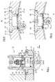
- die schematische Darstellung eines Druckwerkszylinders mit Lagerzapfen, der in einer gestellfesten Aufnahme gelagert ist, auf der ein druckmittelbeaufschlagbares Ventil angeordnet ist;
- Fig. 2
- den Schnitt II - II nach Fig. 1, jedoch mit gemeinsamer Darstellung des Wellenzapfens;
- Fig. 3
- eine Darstellung gemäß Fig. 2, jedoch in Arbeitsstellung;
- Fig. 4
- den Schnitt IV - IV nach Fig. 3;
- Fig. 5
- eine Darstellung nach Fig. 2, jedoch mit einer zweiten Ausführungsvariante eines Ventils in Ruhestellung;
- Fig. 6
- eine Darstellung nach Fig. 5, jedoch in Arbeitsstellung.
- Gemäß Fig. 1 weist ein Druckwerkszylinder 1 beidseitig Schmitzringe bzw. Laufringe 2; 3 sowie gestellfest gelagerte Achszapfen 4 oder/und Achszapfen 6 auf. Der Achszapfen 4 besitzt radial an seinem Umfang verteilte Bohrungen 7, beispielsweise acht Stück. Diese Bohrungen 7, die zunächst radial verlaufen, münden nach einem kurzen Weg in axial verlaufende Bohrungen 8. Diese Bohrungen 7; 8 bilden Druckmittelleitungen, die zu nicht dargestellten Stellelementen führen. Die Erfindung kann jedoch auch bei laufringlosen Druckwerkszylindern Anwendung finden.
- Der Druckwerkszylinder 1 kann beispielsweise auch als Formzylinder ausgeführt sein; und die Druckmittelleitungen führen zu nicht dargestellten Stellelementen, die Spannleisten zum Halten von biegsamen Druckplatten betätigen können.
- Neben dem Achszapfen 4 ist eine rohrförmige Aufnahme 9 dargestellt. Die ringförmige Aufnahme 9 ist an einer nicht dargestellten Lagerbüchse festgeschraubt, welche in einem nicht dargestellten Seitengestell der Maschine gehalten ist. Außen auf der Aufnahme 9 befindet sich eine druckmittelbeaufschlagbare Zuführung 12, die in Fig. 2 bis Fig. 4 näher beschrieben wird. Es kann auch ein Ventil 44 eingesetzt werden, das in Fig. 5 und 6 dargestellt ist.
- Im Betriebszustand befindet sich der Achszapfen 4 in der gestellfesten Aufnahme 9, und zwar so, daß die radialen Bohrungen 7 bei Drehung des Druckwerkszylinders 1 mit der Mittellinie 13 der Zuführung 12 fluchten, d. h. in einer Ebene liegen.
- Gemäß Fig. 2 ist die Zuführung 12 in eine Öffnung 14 der rohrförmigen Aufnahme 9 eingelassen und ist mittels eines Flansches 16; und angedeuteten Schrauben 18; 19 mit der Aufnahme 9 verbunden. Die insgesamt mit 12 bezeichnete Zuführung besteht aus einem rohrförmigen Gehäuse 21, das durch eine konzentrisch angeordnete Scheibe 22 in zwei Räume geteilt ist; in einen oberen Raum 23, der eine Kolbenstange 26 aufnimmt, und in einen unteren Raum 24, der einen Kolben 27 aufnimmt.
- Der Kolben 27 ist in dem Raum 24 um eine Hublänge a in radialer Richtung des Druckwerkszylinders 1 bewegbar und nimmt dann die Arbeitsstellung nach Fig. 3 und 4 ein. Der Kolben 27 besitzt einen an seinem Umfang verlaufenden Dichtring 28, der den Kolben 27 gegen die Innenwand des Gehäuses 21 abdichtet.
- Am Kolbenboden 20 ist die Kolbenstange 26 befestigt, welche durch eine in der Scheibe 22 befindliche zentrische Bohrung 29 in den oberen Raum 23 ragt. Die Kolbenstange 26 weist an ihrem freien Ende ein Außengewinde mit Mutter 31 auf, wogegen eine zwischen der Mutter 31 und der Scheibe 22 angeordnete Druckfeder 32 drückt.
- Die Kolbenstange 26 weist zentrisch eine in axialer Richtung verlaufende Bohrung 33 auf, die weiterhin in gleicher Richtung durch den Kolben 27 verläuft und am Kolbenboden 20, d. h. an seiner Stirnseite, in einem nutförmigen Auslaß 34 mit einer Nutlänge b endet. Gemäß Fig. 4 besitzt der Auslaß 34 eine Nutbreite c. Die besagte Stirnseite des Kolbens 27 mit dem Auslaß 34 fungiert als Gleitschuh auf dem Achszapfen 4 und ist diesem mit seiner Oberfläche angepaßt.
- Die Scheibe 22 weist eine Anzahl konzentrisch angeordneter Bohrungen 36 auf, die um die zentrische Bohrung 29 verlaufen und welche den oberen Raum 23 mit dem unteren Raum 24 verbinden. Der obere Raum 23 wird durch einen Gehäusedeckel 37 mit Einlaß 38 abgeschlossen. Der Gehäusedeckel 37 sowie das Gehäuse 21 und die Scheibe 22 sind durch Gewindeschrauben 39 miteinander verbunden.
- Der Kolben 27 weist an einer Stelle seines Bodens einen Führungsstift 40 auf, der parallel zur Kolbenstange 26 verläuft und durch eine der konzentrisch angeordneten Bohrungen 36 ragt. Der Führungsstift 40 dient als Verdrehsicherung für den Gleitschuh.
- Die Funktionsweise der Einrichtung wird nachfolgend beschrieben.
- Gemäß Fig. 2 bewegt sich der Druckwerkszylinder 1 in Pfeilrichtung D. Durch den Einlaß 38 wird beispielsweise Druckluft von einer nicht dargestellten Druckluftquelle zugeführt. Der Verlauf der Druckluft ist in den Fig. 3 und 4 durch kleine Pfeile angezeigt.
- Nachdem der Druckwerkszylinder 1 gemäß Fig. 3 die Position 41 als gestrichelte Darstellung der Bohrungen 7; 8 erreicht hat, ist auch der Kolben 27 um den Betrag der Hublänge a in Richtung Druckwerkszylinder 1 vorgerückt und wirkt auf der Oberfläche des Achszapfens 4 als Gleitschuh mit abdichtender Funktion.
- Die in den oberen Raum 23 eingeströmte Druckluft strömt dabei einerseits durch die konzentrischen Bohrungen 36 und drückt auf den Boden des Kolbens 27, der sich entgegen der Kraft der Druckfeder 32 und der Reibung des Kolbens 27 und des Dichtringes 28 an der Innenwand des unteren Raumes 24 um die Hublänge a bewegt. Andererseits dringt die zugeführte Luft in die Bohrung 33 der Kolbenstange 26 ein und gelangt über die Nut 34 zu der durch die Bohrungen 7; 8 ausgebildeten Druckmittelleitung zwecks Betätigung von nicht dargestellten Stellorganen.
- Aufgrund der Drosselwirkung der Bohrung 33 baut sich bei Luftzufuhr im Raum 23 und über die Bohrung 36 auch im Raum 24 ein Überdruck auf, wodurch der Kolben 27 aus seiner Ruhelage bewegt wird.
- Druckmittelleitung dauert während der Drehbewegung des Druckwerkszylinders 1 solange, bis die Nut mit der Länge b außer Kontakt kommt mit der radialen Bohrung 7. Diese Luftzuführung kann auch durch nicht dargestellte Mittel, beispielsweise durch ein Ventil, unterbrochen werden.
- Um die Leckageverluste gering zu halten, ist eine Mindestpressung zwischen Gleitschuh und Oberfläche des Achszapfens 4 erforderlich. Durch seitliche Ausnehmungen 42; 43 an der Stirnseite des Kolbens 27 gemäß Fig. 4 ist gesichert, daß die Fläche des Gleitschuhs geringer ist als die druckmittelbeaufschlagte Bodenfläche 25 des Kolbens 27, so daß sich eine entsprechende Fugenpressung mit ausreichender Dichtwirkung einstellt.
- Nun dreht sich der Druckwerkszylinder 1 weiter in Pfeilrichtung D, um mit der nächsten Bohrung 7 - wie in Fig. 1 dargestellt - in Kontakt zu kommen, die als beaufschlagte Druckmittelleitung ebenfalls eine andere Stellbewegung auslöst. Solche Stellbewegungen können beispielsweise zum Betätigen von Spannleisten für Druckplatten dienen, falls der Druckwerkszylinder 1 als Formzylinder ausgeführt ist.
- Die Breite c der Nut 34 ist gemäß Fig. 4 größer als die Bohrung 7. Dies ist insbesondere dann von Vorteil, wenn der Druckwerkszylinder 1 als Formzylinder ausgeführt ist und infolge von Registerverstellungen in axialer Richtung gemäß Pfeil E eine Bewegung erfährt und dadurch bedingt nicht an eine eindeutige axiale Lage fixiert ist.
- Als Medium für das Druckmittel kann sowohl Luft als auch Öl Verwendung finden.
- Es ist auch möglich, das Ventil 12 dann einzusetzen, wenn durch die Bohrungen 7; 8 Saugluft gefördert wird, d. h. wenn der Druckwerkszylinder 1 mit Saugluft beaufschlagt wird. Für diesen Fall wird eine nicht dargestellte Saugluftleitung an die Bohrung 33 der Kolbenstange 26 angeschlossen. Durch den Einlaß 38 wird nach wie vor Druckluft zugeführt, um den Kolben 27 um die Hublänge a zu betätigen.
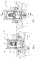
- Gemäß Fig. 5 ist eine zweite Ausführungsvariante einer insgesamt mit 44 bezeichneten Zuführung in Ruhestellung und nach Fig. 6 in Arbeitsstellung dargestellt.
- Die insgesamt mit 44 bezeichnete Zuführung besteht aus einem topfartigen Gehäuse, welches einen Boden 46, eine zylinderförmig verlaufende Seitenwand 47 und einen Rand 48 aufweist. Unterhalb seines Randes 48 ist das Gehäuse mit einem scheibenförmigen Verschluß 49 aus elastischem Material, beispielsweise Gummi, versehen. Der Verschluß 49 besitzt eine zentrisch angeordnete Öffnung als Auslaß 51 und kann zwischen der Seitenwand 47 und dem Rand 48 mittels Schrauben 52 befestigt sein. Der Boden 46 weist einen Einlaß 53 für das Druckmittel sowie zwei Laschen 54; 56 auf. Die Laschen 54; 56 sind mittels Gewindeschrauben 57 auf der rohrförmigen Aufnahme 9 befestigt. Die Aufnahme 9 ist fest am nicht dargestellten Maschinengestell angebracht.
- Im Betriebszustand nach Fig. 6 wird durch den Einlaß 53 Druckluft eingebracht, die im Innenraum des Gehäuses einen Überdruck aufbaut. der elastische Verschluß 49 wölbt sich in Richtung Achszapfen 4. Die Öffnung 51 kommt zur Anlage mit einer der Bohrungen 7, nachdem sich der Achszapfen 4 gemäß Pfeilrichtung D bewegt hat. Die Druckluft wird über die Bohrungen 7; 8 als Druckmittelleitung weitergeführt zu nicht dargestellten Betätigungsorganen des Druckwerkszylinders 1 nach Fig. 1.
- Der Auslaß 51 ist größer als der Durchmesser der Bohrungen 7, so daß während der Bewegung des Achszapfens 4 in Pfeilrichtung D analog den Fig. 3 und 4 eine Dimensionierung der Öffnung 51 in Richtung a und b erfolgt.
- Nach Abfall der Druckluftzufuhr erfolgt die selbsttätige Rückstellung durch die Rückstellkräfte des elastischen Verschlusses 49 in die Lage nach Fig. 1. Die Dichtung zwischen Verschluß 49 und der Oberfläche des Achszapfens 4 erfolgt nahezu verlustlos.
- Als Druckmittel kann auch eine Flüssigkeit, beispielsweise Öl, eingesetzt werden.
-
- 1
- Druckwerkszylinder
- 2
- Laufring; Schmitzring
- 3
- Laufring; Schmitzring
- 4
- Wellenzapfen
- 5
- -
- 6
- Wellenzapfen
- 7
- Bohrung, radial
- 8
- Bohrung, axial
- 9
- Aufnahme, rohrförmig
- 10
- -
- 11
- -
- 12
- Zuführung
- 13
- Mittellinie
- 14
- Öffnung
- 15
- -
- 16
- Flansch
- 17
- -
- 18
- Schraube
- 19
- Schraube
- 20
- Kolbenboden
- 21
- Gehäuse
- 22
- Scheibe
- 23
- Raum, oberer
- 24
- Raum, unterer
- 25
- Bodenfläche (27)
- 26
- Kolbenstange
- 27
- Kolben
- 28
- Dichtring
- 29
- Bohrung, zentrisch (22)
- 30
- -
- 31
- Mutter
- 32
- Druckfeder
- 33
- Bohrung (26; 27)
- 34
- Auslaß
- 35
- -
- 36
- Bohrungen, konzentrisch (22)
- 37
- Gehäusedeckel
- 38
- Einlaß
- 39
- Gewindeschrauben
- 40
- Führungsstift
- 41
- Position (7; 8)
- 42
- Ausnehmung
- 43
- Ausnehmung
- 44
- Zuführung
- 45
- -
- 46
- Boden
- 47
- Seitenwand
- 48
- Rand
- 49
- Verschluß
- 50
- -
- 51
- Auslaß
- 52
- Schraube
- 53
- Einlaß
- 54
- Lasche
- 55
- -
- 56
- Lasche
- 57
- Schraube
- a
- Hublänge
- b
- Nutlänge (34)
- c
- Nutbreite
- D
- Bewegungsrichtung
- E
- Bewegungsrichtung
Claims (11)
- Zuführung (12; 44) zum Beaufschlagen von Druckmittelleitungen (7, 8) auf über Achszapfen rotierbar gelagerten Körpern (1) mit einem druckbeaufschlagbaren Medium, wobei die Zuführung (12; 44) gestellfest gelagert ist und mindestens einen gestellfesten Einlaß (38; 53) und mindestens einen mit einem Ende (7) der Druckmittelleitung (7, 8) in Überdeckung bringbaren Auslaß (34; 51) für das druckbeaufschlagte Medium aufweist, dadurch gekennzeichnet, daß der Auslaß (34; 51) in Richtung Ende (7) der Druckmittelleitungen (7, 8) senk- und hebbar angeordnet ist und daß der Auslaß (34; 51) in Richtung Ende (7) der Druckmittelleitungen (7, 8) mittels des druckmittelbeaufschlagten Mediums selbst bei Beaufschlagung der Druckmittelleitungen (7, 8) hinbewegbar angeordnet ist, wobei die Enden der Druckmittelleitungen (7, 8) in die Umfangsoberfläche der mit dem Körper (1) rotierbaren Achszapfen des Körpers (1) münden.
- Zuführung nach Patentanspruch 1, dadurch gekennzeichnet, daß die Zuführung (12) aus einem rohrförmigen Gehäuse (21) besteht, die durch eine konzentrisch angeordnete Scheibe (22) in einen oberen Raum (23) zur Aufnahme einer Kolbenstange (26) und einen unteren Raum (24) zur Aufnahme eines Kolbens (27) geteilt ist, daß die Scheibe (22) eine zentrisch angeordnete Bohrung (29) zwecks Durchführung der Kolbenstange (26) und einige auf einem konzentrischen Kreis angeordnete Bohrungen (36) aufweist, daß die Kolbenstange (26) eine axiale Bohrung (33) aufweist, die sich bis zur Stirnseite des Kolbens (27) erstreckt und dort in einer Öffnung (37) endet, daß zwischen dem Ende der Kolbenstange (26) und der Scheibe (22) eine Rückstellfeder (32) angeordnet ist und der obere Raum (23) durch einen Gehäusedeckel (37) mit einem Einlaß (38) abgeschlossen ist.
- Zuführung nach den Patentansprüchen 1 und 2, dadurch gekennzeichnet, daß die Öffnung aus einem am Kolbenende in einem Gleitschuh angeordneten Auslaß (34) besteht.
- Zuführung nach Patentanspruch 1, dadurch gekennzeichnet, daß die Zuführung (44) aus einem topfartigen Gehäuse (46,.47, 48) besteht, das an seiner Seitenwand (47) unterhalb seines Randes (48) einen scheibenförmigen Verschluß (49) aus elastischem Material mit einem zentrisch angeordneten Auslaß (51) und an seinem Boden (46) einen Einlaß (53) besitzt.
- Zuführung nach den Patentansprüchen 1 und 4, dadurch gekennzeichnet, daß der scheibenförmige verschluß (49) zwischen dem Rand (48) des Gehäuses und der Seitenwand (47) befestigt ist.
- Zuführung nach den Patentansprüchen 1, 4 und 5, dadurch gekennzeichnet, daß der Boden (46) des Gehäuses Befestigungslaschen (54; 56) aufweist.
- Zuführung nach den Patentansprüchen 1 bis 6, dadurch gekennzeichnet, daß die Zuführung (12; 44) in einer auf dem Wellenzapfen (4; 6) angeordneten rohrförmigen Aufnahme (9) befestigt ist, daß die Aufnahme (9) mit einer gestellfesten Lagerbüchse verbunden ist.
- Zuführung nach den Patentansprüchen 1 bis 6, dadurch gekennzeichnet, daß die Zuführung (12; 44) in einer auf dem Wellenzapfen (4; 6) angeordneten rohrförmigen Aufnahme (9) befestigt ist, daß die Aufnahme (9) mit einer gestellfesten Lagerbüchse drehbar verbunden ist.
- Zuführung nach den Patentansprüchen 1 bis 3, dadurch gekennzeichnet, daß eine wirksame Fläche des Gleitschuhes (27, 34) kleiner ist als ein Boden (25) des druckluftbeaufschlagbaren Kolbens (27).
- Zuführung nach den Patentansprüchen 1 bis 9, dadurch gekennzeichnet, daß der Auslaß (34) des Gleitschuhes (27, 34) sowie der Auslaß (51) der Zuführung (12; 44) in einer Ebene verlaufen mit den radial am Umfang des Achszapfens (4) angeordneten Bohrungen (7).
- Zuführung nach den Patentansprüchen 1 bis 10, dadurch gekennzeichnet, daß die im Achszapfen (4; 6) verlaufenden radialen Bohrungen (7) am Umfang des Achszapfens (4; 6) fluchtend angeordnet sind.
Applications Claiming Priority (2)
| Application Number | Priority Date | Filing Date | Title |
|---|---|---|---|
| DE4203550A DE4203550C2 (de) | 1992-02-07 | 1992-02-07 | Drehzuführung für druckbeaufschlagbare Medien auf rotierbare Körper |
| DE4203550 | 1992-02-07 |
Publications (2)
| Publication Number | Publication Date |
|---|---|
| EP0554815A1 EP0554815A1 (de) | 1993-08-11 |
| EP0554815B1 true EP0554815B1 (de) | 1997-09-03 |
Family
ID=6451186
Family Applications (1)
| Application Number | Title | Priority Date | Filing Date |
|---|---|---|---|
| EP93101477A Expired - Lifetime EP0554815B1 (de) | 1992-02-07 | 1993-01-30 | Zuführeinrichtung für druckbeaufschlagbare Medien auf rotierbare Körper, vorzugsweise Zylinder in Druckmaschinen |
Country Status (4)
| Country | Link |
|---|---|
| US (1) | US5255604A (de) |
| EP (1) | EP0554815B1 (de) |
| JP (1) | JP2777038B2 (de) |
| DE (2) | DE4203550C2 (de) |
Cited By (1)
| Publication number | Priority date | Publication date | Assignee | Title |
|---|---|---|---|---|
| DE102004021606B4 (de) * | 2004-05-03 | 2007-03-29 | Koenig & Bauer Ag | Formzylinder mit einem Drehübertrager zum Einführen eines flüssigen oder gasförmigen Mediums in den Formzylinder einer Druckmaschine |
Families Citing this family (14)
| Publication number | Priority date | Publication date | Assignee | Title |
|---|---|---|---|---|
| DE4340651C1 (de) * | 1993-11-30 | 1995-03-09 | Koenig & Bauer Ag | Formzylinder mit schlitzförmiger Druckplatteneinführung |
| DE4407239A1 (de) * | 1994-03-04 | 1995-09-07 | Schwaebische Huettenwerke Gmbh | Dampfbeheizte Walze |
| US5481975A (en) * | 1994-10-03 | 1996-01-09 | Schulz; Werner | Printing cylinder mandrel and image carrier sleeve |
| US5507228A (en) * | 1994-10-03 | 1996-04-16 | Schulz; Werner | Printing cylinder |
| US5711223A (en) * | 1995-08-14 | 1998-01-27 | Eugene L. Green, Sr. | Magnetic plate cylinder |
| DE29600845U1 (de) * | 1996-01-19 | 1996-03-07 | MAN Roland Druckmaschinen AG, 63075 Offenbach | Vorrichtung zum Befestigen einer Bespannung auf einem Druckwerkzylinder |
| DE19636412C1 (de) * | 1996-09-07 | 1998-01-08 | Koenig & Bauer Albert Ag | Zylinder |
| DE19840310A1 (de) * | 1998-09-04 | 2000-03-09 | Kammann Maschf Werner | Rotationsdruckmaschine |
| DE19961866A1 (de) * | 1999-12-22 | 2001-06-28 | Roland Man Druckmasch | Vorrichtung zur Zufuhr eines Druckmediums zu einem eine Druckform oder ein Gummituch tragenden Zylinder |
| DE10015165B4 (de) * | 2000-03-27 | 2004-01-29 | Koenig & Bauer Ag | Vorrichtung zur Zuführung von Druckmittel |
| DE10122227B4 (de) * | 2001-05-08 | 2012-03-01 | Koenig & Bauer Aktiengesellschaft | Speichertrommel in Wendeeinrichtungen von Bogendruckmaschinen |
| DE10305593A1 (de) | 2002-03-15 | 2003-09-25 | Heidelberger Druckmasch Ag | Drehdurchführung zur Versorgung eines Rotors einer bedruckstoffverarbeitenden Maschine mit einem Arbeitsfluid |
| DE102008025222B3 (de) * | 2008-05-27 | 2009-07-09 | WINKLER+DüNNEBIER AG | Ortsfeste radiale Druckluftzuführung |
| CN103921546A (zh) * | 2013-01-14 | 2014-07-16 | 江苏昌昇集团股份有限公司 | 一种胶印机印版气动装夹机构 |
Citations (2)
| Publication number | Priority date | Publication date | Assignee | Title |
|---|---|---|---|---|
| JPS5919156A (ja) * | 1982-07-23 | 1984-01-31 | Komori Printing Mach Co Ltd | 印刷機用ロ−タリバルブ装置 |
| DE3833684A1 (de) * | 1987-10-22 | 1989-05-03 | Barkas Werke Veb | Zweikanalige drehdurchfuehrung zum unabhaengigen beaufschlagen von druckraeumen in umlaufenden systemen |
Family Cites Families (5)
| Publication number | Priority date | Publication date | Assignee | Title |
|---|---|---|---|---|
| US4005653A (en) * | 1974-09-09 | 1977-02-01 | Livermore And Knight Co., Inc. | Vacuum cylinder for printing presses |
| JPS5163708A (de) * | 1974-09-26 | 1976-06-02 | Emu Ei Batsukuree Engureibingu | |
| GB2137140B (en) * | 1983-03-10 | 1986-03-26 | Mosstype Corp | Printing cylinders |
| US4744297A (en) * | 1985-09-17 | 1988-05-17 | The Ward Machinery Company | Mounting printing plates |
| JP2584286B2 (ja) * | 1988-08-23 | 1997-02-26 | 富士写真フイルム株式会社 | 電子写真感光体 |
-
1992
- 1992-02-07 DE DE4203550A patent/DE4203550C2/de not_active Expired - Fee Related
-
1993
- 1993-01-30 DE DE59307225T patent/DE59307225D1/de not_active Expired - Fee Related
- 1993-01-30 EP EP93101477A patent/EP0554815B1/de not_active Expired - Lifetime
- 1993-02-03 US US08/012,647 patent/US5255604A/en not_active Expired - Lifetime
- 1993-02-03 JP JP5016090A patent/JP2777038B2/ja not_active Expired - Fee Related
Patent Citations (2)
| Publication number | Priority date | Publication date | Assignee | Title |
|---|---|---|---|---|
| JPS5919156A (ja) * | 1982-07-23 | 1984-01-31 | Komori Printing Mach Co Ltd | 印刷機用ロ−タリバルブ装置 |
| DE3833684A1 (de) * | 1987-10-22 | 1989-05-03 | Barkas Werke Veb | Zweikanalige drehdurchfuehrung zum unabhaengigen beaufschlagen von druckraeumen in umlaufenden systemen |
Cited By (2)
| Publication number | Priority date | Publication date | Assignee | Title |
|---|---|---|---|---|
| DE102004021606B4 (de) * | 2004-05-03 | 2007-03-29 | Koenig & Bauer Ag | Formzylinder mit einem Drehübertrager zum Einführen eines flüssigen oder gasförmigen Mediums in den Formzylinder einer Druckmaschine |
| US7650837B2 (en) | 2004-05-03 | 2010-01-26 | Koenig & Bauer Aktiengesellschaft | Printing machine having a rotation transmitter for introducing a liquid or gaseous medium |
Also Published As
| Publication number | Publication date |
|---|---|
| JPH05269968A (ja) | 1993-10-19 |
| US5255604A (en) | 1993-10-26 |
| DE4203550A1 (de) | 1993-08-12 |
| EP0554815A1 (de) | 1993-08-11 |
| DE59307225D1 (de) | 1997-10-09 |
| JP2777038B2 (ja) | 1998-07-16 |
| DE4203550C2 (de) | 1995-07-13 |
Similar Documents
| Publication | Publication Date | Title |
|---|---|---|
| DE4203550C2 (de) | Drehzuführung für druckbeaufschlagbare Medien auf rotierbare Körper | |
| DE2038965B2 (de) | Hydraulischer motor | |
| DE69719169T2 (de) | Nockenbetriebener motor | |
| EP1179149B1 (de) | Dichtungsvorrichtung für einen mit druckmittel beaufschlagten kolben in einem arbeitszylinder | |
| EP0620358A1 (de) | Hydraulikmotor | |
| DE3643287C2 (de) | ||
| EP1269062A1 (de) | Verfahren und vorrichtung zur zuführung von druckmittel | |
| EP0719640B1 (de) | Zylinder einer Rotationsdruckmaschine | |
| EP0453788B1 (de) | Vorrichtung zum An-, Ab- und Einstellen von Farbauftragwalzen | |
| EP0809736B1 (de) | Drehvorrichtung für baggergreifer | |
| EP0797739B1 (de) | Druckmittelbetätigte kupplung und bremse | |
| DE2552677C3 (de) | Hydrostatische Radialkolbenmaschine | |
| DE2559645C3 (de) | Druckmittelbetätigte Ausrückkupplung | |
| DE3321084A1 (de) | Stangendichtung | |
| DE4104712A1 (de) | Radialkolbenmaschine mit mechanischer bremseinrichtung | |
| DE2821414C2 (de) | Laufrad für einen Axialverdichter | |
| DE9216171U1 (de) | Zuführeinrichtung für druckbeaufschlagbare Medien auf rotierbare Körper, vorzugsweise Zylinder in Druckmaschinen | |
| DE60005496T2 (de) | Differentialsperre | |
| DE3801348A1 (de) | Reibungskupplung mit schalteinrichtung | |
| EP0074496B1 (de) | Ventilvorrichtung, insbesondere für Druckgiessmaschinen | |
| DE2717353B2 (de) | Hydraulisch betätigte Schaltvorrichtung | |
| DE10029305A1 (de) | Dichtungsvorrichtung für einen mit Druckmittel beaufschlagten Kolben in einem Arbeitszylinder | |
| DE4308126A1 (de) | Verfahren und Vorrichtung zum Verstellen von Druckzylindern | |
| DE1653524B2 (de) | Hydraulische Radialkolbenmaschine mit schwingenden Zylindern | |
| CH563543A5 (de) |
Legal Events
| Date | Code | Title | Description |
|---|---|---|---|
| PUAI | Public reference made under article 153(3) epc to a published international application that has entered the european phase |
Free format text: ORIGINAL CODE: 0009012 |
|
| AK | Designated contracting states |
Kind code of ref document: A1 Designated state(s): CH DE FR GB IT LI SE |
|
| 17P | Request for examination filed |
Effective date: 19930903 |
|
| 17Q | First examination report despatched |
Effective date: 19950203 |
|
| RAP1 | Party data changed (applicant data changed or rights of an application transferred) |
Owner name: KOENIG & BAUER-ALBERT AKTIENGESELLSCHAFT |
|
| GRAG | Despatch of communication of intention to grant |
Free format text: ORIGINAL CODE: EPIDOS AGRA |
|
| GRAH | Despatch of communication of intention to grant a patent |
Free format text: ORIGINAL CODE: EPIDOS IGRA |
|
| ITF | It: translation for a ep patent filed | ||
| GRAH | Despatch of communication of intention to grant a patent |
Free format text: ORIGINAL CODE: EPIDOS IGRA |
|
| GRAA | (expected) grant |
Free format text: ORIGINAL CODE: 0009210 |
|
| AK | Designated contracting states |
Kind code of ref document: B1 Designated state(s): CH DE FR GB IT LI SE |
|
| REG | Reference to a national code |
Ref country code: CH Ref legal event code: EP |
|
| ET | Fr: translation filed | ||
| GBT | Gb: translation of ep patent filed (gb section 77(6)(a)/1977) |
Effective date: 19970905 |
|
| REF | Corresponds to: |
Ref document number: 59307225 Country of ref document: DE Date of ref document: 19971009 |
|
| PLBE | No opposition filed within time limit |
Free format text: ORIGINAL CODE: 0009261 |
|
| STAA | Information on the status of an ep patent application or granted ep patent |
Free format text: STATUS: NO OPPOSITION FILED WITHIN TIME LIMIT |
|
| 26N | No opposition filed | ||
| REG | Reference to a national code |
Ref country code: GB Ref legal event code: IF02 |
|
| PGFP | Annual fee paid to national office [announced via postgrant information from national office to epo] |
Ref country code: IT Payment date: 20060131 Year of fee payment: 14 |
|
| PGFP | Annual fee paid to national office [announced via postgrant information from national office to epo] |
Ref country code: DE Payment date: 20060316 Year of fee payment: 14 |
|
| PGFP | Annual fee paid to national office [announced via postgrant information from national office to epo] |
Ref country code: SE Payment date: 20070115 Year of fee payment: 15 |
|
| PGFP | Annual fee paid to national office [announced via postgrant information from national office to epo] |
Ref country code: CH Payment date: 20070117 Year of fee payment: 15 |
|
| PGFP | Annual fee paid to national office [announced via postgrant information from national office to epo] |
Ref country code: GB Payment date: 20070119 Year of fee payment: 15 |
|
| PG25 | Lapsed in a contracting state [announced via postgrant information from national office to epo] |
Ref country code: DE Free format text: LAPSE BECAUSE OF NON-PAYMENT OF DUE FEES Effective date: 20070801 |
|
| PGFP | Annual fee paid to national office [announced via postgrant information from national office to epo] |
Ref country code: FR Payment date: 20070112 Year of fee payment: 15 |
|
| REG | Reference to a national code |
Ref country code: CH Ref legal event code: PL |
|
| EUG | Se: european patent has lapsed | ||
| GBPC | Gb: european patent ceased through non-payment of renewal fee |
Effective date: 20080130 |
|
| PG25 | Lapsed in a contracting state [announced via postgrant information from national office to epo] |
Ref country code: LI Free format text: LAPSE BECAUSE OF NON-PAYMENT OF DUE FEES Effective date: 20080131 Ref country code: CH Free format text: LAPSE BECAUSE OF NON-PAYMENT OF DUE FEES Effective date: 20080131 |
|
| REG | Reference to a national code |
Ref country code: FR Ref legal event code: ST Effective date: 20081029 |
|
| PG25 | Lapsed in a contracting state [announced via postgrant information from national office to epo] |
Ref country code: GB Free format text: LAPSE BECAUSE OF NON-PAYMENT OF DUE FEES Effective date: 20080130 |
|
| PG25 | Lapsed in a contracting state [announced via postgrant information from national office to epo] |
Ref country code: SE Free format text: LAPSE BECAUSE OF NON-PAYMENT OF DUE FEES Effective date: 20080131 |
|
| PG25 | Lapsed in a contracting state [announced via postgrant information from national office to epo] |
Ref country code: FR Free format text: LAPSE BECAUSE OF NON-PAYMENT OF DUE FEES Effective date: 20080131 |
|
| PG25 | Lapsed in a contracting state [announced via postgrant information from national office to epo] |
Ref country code: IT Free format text: LAPSE BECAUSE OF NON-PAYMENT OF DUE FEES Effective date: 20070130 |