EP0554702A1 - Chemin de câblage, en particulier pour la disposition des fils - Google Patents
Chemin de câblage, en particulier pour la disposition des fils Download PDFInfo
- Publication number
- EP0554702A1 EP0554702A1 EP93100688A EP93100688A EP0554702A1 EP 0554702 A1 EP0554702 A1 EP 0554702A1 EP 93100688 A EP93100688 A EP 93100688A EP 93100688 A EP93100688 A EP 93100688A EP 0554702 A1 EP0554702 A1 EP 0554702A1
- Authority
- EP
- European Patent Office
- Prior art keywords
- insert
- cable duct
- cable
- base body
- holding elements
- Prior art date
- Legal status (The legal status is an assumption and is not a legal conclusion. Google has not performed a legal analysis and makes no representation as to the accuracy of the status listed.)
- Withdrawn
Links
Images
Classifications
-
- H—ELECTRICITY
- H02—GENERATION; CONVERSION OR DISTRIBUTION OF ELECTRIC POWER
- H02G—INSTALLATION OF ELECTRIC CABLES OR LINES, OR OF COMBINED OPTICAL AND ELECTRIC CABLES OR LINES
- H02G3/00—Installations of electric cables or lines or protective tubing therefor in or on buildings, equivalent structures or vehicles
- H02G3/02—Details
- H02G3/04—Protective tubing or conduits, e.g. cable ladders or cable troughs
- H02G3/0437—Channels
Definitions
- the invention relates to a cable duct, in particular a wiring duct, the housing of which consists of a lower part and a cover which can be detachably connected therewith, wherein holding elements are arranged in the lower part, or the like for attaching electrical installation parts, such as cable ties, cable tie holders. or of partitions, subdivisions or the like. serve.
- Such cable ducts are known in manifold embodiments.
- the holding elements used are usually attached to the inside of the bottom of the lower part and designed as a continuous strip-shaped body. These strip-shaped holding elements are often mushroom-shaped in cross-section. What the attachment of partitions, subdivisions or the like. concerns, these known cable ducts have proven themselves because you can easily put the partitions on the retaining elements designed as strips.
- there are difficulties with the known embodiments of cable ducts when, for example, cable ties are to be accommodated in the interior of the lower part of the housing of the cable duct. These cable ties have the advantage in themselves that they have an order function, because with them one Bundling of the numerous cables, lines or the like arranged in the cable duct. is possible.
- the invention has for its object to design cable ducts of the type characterized in more detail above in such a way that a simpler accommodation and arrangement of cable ties or the like. is possible in the interior of the lower part of the cable duct.
- the holding elements are assigned to an insert which in turn can be detachably connected to the walls, preferably the side walls of the lower part of the cable duct, and that a plurality of inserts are arranged one behind the other in the longitudinal direction of the cable duct, the mutual The distance between neighboring inserts can be freely selected.
- the cable duct according to the invention has considerable advantages in comparison with the known embodiments.
- First the inside of the bottom of the lower part can be kept completely smooth, so that there is no need to attach the retaining strips which run in the longitudinal direction of the cable duct and which are molded onto the bottom.
- the holding elements are assigned to an insert, which in turn can be releasably connected to diametrically opposite walls of the lower part.
- Several such inserts with holding elements can be assigned to one and the same cable duct. The user is free to determine the number of inserts with holding elements to be attached per unit length of the cable duct and also to determine the mutual distance of the inserts with the holding elements from one another; he is not dependent on compliance with certain dimensions and dimensions.
- the insert has mating strips which cooperate with strips on the inside of the side walls of the lower part of the cable duct, in such a way that the insert can be clipped in at a freely selectable location in the lower part of the cable duct.
- the attachment of the insert according to the invention is therefore extremely simple. A simple clip-in of the insert is sufficient, the further advantage being that it is possible to remove the insert from the lower part of the cable duct if necessary.
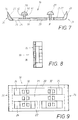
- the insert has a plate-shaped base body, which has a plurality of holding elements on its upper side facing the cover of the cable duct and guide ducts for cable ties on its underside, which are connected to the underside of the basic body via openings. Counter strips are arranged on the plate-shaped base body at diametrically opposite end parts.
- the plate-shaped base body of the insert has a plurality of parallel and spaced-apart longitudinal webs which are connected to one another by a plurality of transverse webs or end parts, and that regions of the upper side of the webs serve to attach the holding elements, while spaces between the webs Form openings which open into guide channels on the underside of the base body.
- a plate-shaped base body can be manufactured as a one-piece plastic body.
- the like or at least one of the boundary walls of the openings of the base body to facilitate the insertion of a cable tie. to have a slope. This bevel causes a targeted insertion of one end of the cable tie into the guide channel on the underside of the plate-shaped base body of the insert.
- the bevels of those openings of the base body of the insert which are adjacent to the end parts merge into ramps which are followed by an outlet tip.
- the ramps also have an angle of inclination which facilitates the insertion or removal of the ends of the cable ties from the plate-shaped base body of the insert.
- each holding element has a head in a manner known per se, the underside of which has a shoulder or the like for attaching a partition to an inner channel. has, which merges into a connecting web, which in turn is molded onto the base body of the insert.
- these holding elements can be arranged one behind the other in the transverse direction of the insert.
- the webs of the holding elements can also be connected to one another by cross connectors.
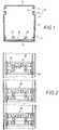
- the cable duct shown in FIGS. 1, 3, 4 and 5 has a design known per se. It is representative of other cable channels in which the invention can be used.
- the cable duct shown differs from the known primarily only in that its bottom is kept clear of continuous holding strips.
- the cable duct thus has a smooth, continuous inner floor.
- the cable duct on which the exemplary embodiment is based is generally designated by 10.
- the cable duct has an approximately U-shaped lower part 11 seen in cross section, the upright side walls of which are designated by 12, these are connected to each other by the horizontal bottom 13.
- the upper free ends of the side walls 12 have known catches 14, which interact with counter catches 16 of the cover 15.
- the connection of the cover 15 is done by simply clipping onto the lower part 11.
- the design of both the catches 14 and the counter-catches 16 is known. Instead of the designs and designs shown, other forms of latching can also be used.
- Continuous strips 17 are arranged on the inside of the side walls 12 in the vicinity of the base 13 and cooperate with counter strips 28 of an insert generally designated 18.
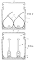
- connection of the insert 18 to the inside of the side wall 12 is made by simply clipping in, the strips 17 and the counter strips 28 coming into engagement with one another. It is a detachable connection, so that it can be removed again from the interior of the lower part 11 of the cable duct 10 at any time.
- the insert 18 has a plate-shaped base body 19 which has a plurality of holding elements 29 on its side facing the cover 15 of the cable duct 10 and guide ducts 36 for cable ties 37 on its underside .
- the cable ties are shown in their effective position in Fig. 3 of the drawing.
- the guide channels 36 for the cable ties 37 are connected to the upper side of the base body 19 via openings 24.
- the counter strips 28 mentioned are formed directly, which cooperate with the strips 27 of the side walls 12 for the purpose of clipping.
- the plate-shaped base body 19 of the insert 18 has a multiplicity of longitudinal webs 20, 21, 22 which run parallel and at a distance from one another and which are separated by a plurality of transverse webs 23 or by the end parts 26 are interconnected. Areas of the upper side of the above-mentioned webs serve to attach the holding elements 29. The spaces between the webs form the openings 24 which open into guide channels 36 which run on the underside of the base body 19. 6 and 7 show that at least one of the boundary walls of the openings 24 of the base body 19 has a bevel 25, this serves to facilitate the insertion of one of the cable ties 37. In addition, FIG.
- each holding element 29 has a head 30, the underside of which has a shoulder 31 for attaching a partition 38 of an inner channel 39 or the like.
- a connecting web 32 is provided lying in the middle, which is molded onto the base body 19 of the insert 18.
- the connecting webs 32 of the three holding elements 29 are shown in the Exemplary embodiment by cross connector 33 in connection.
- FIG. 3 of the drawing shows how the cable ties 37 known per se interact with the insert 18 according to the invention for the cable duct 10. It is assumed in the illustrated embodiment that a total of two cable ties 37 are assigned to a single insert. It can be seen that regions of the strip-shaped cable tie 37 lie in the guide channels on the underside of the base body 19 of the set 18. Due to the recessed mounting of the guide channels 36 in the base body, it is possible for the underside of the base body 19 of the insert 18 to lie fully on the floor 13, even if the cable ties as in FIG. 3 of the drawing in the guide channels of the insert 18 are housed.
- FIG. 4 of the drawing it is shown that also known partition walls 38 can cooperate with the holding elements 29 of the insert 18.
- a partition 38 is assigned to each group of holding elements 29; the connection between the partition 38 and the holding elements 29 is known per se. It should therefore only be mentioned that parts of the fork-shaped lower part of the partition 38 engage under the shoulders 31 of the heads 30 of the holding elements 29. Other parts, namely end regions of the partition, are supported on the top of the base body 19 of the insert 18.
- the insert 18 is assigned an inner channel 39 which is also known per se.
- This inner channel 39 has holding arms which on the one hand interact with the shoulder 31 of the head 30 and on the other hand are laterally supported on the head 30 of the holding element 29.
- electrical lines, cables or the like can also be used in a known manner. be accommodated.
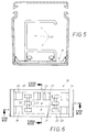
- one and the same lower part 11 of a cable duct 10 is assigned a larger number of inserts 18, which are all mutually identical in the embodiment shown.
- a total of three inserts 18 are accommodated in the interior of the lower part 11 of the cable duct 10.
- the mutual position of the inserted inserts 18 is freely selectable by the user, it is also left open in FIG. 2 whether the parts of the insert with cable ties, partition walls, inner channels or the like. work together.
- the inserts 18 in the lower part 11 of the cable duct 10 it is not absolutely necessary for the inserts 18 in the lower part 11 of the cable duct 10 to be designed identically to one another according to FIG. 2 of the drawing. Rather, it is quite conceivable that one and the same cable duct can be assigned several, differently designed inserts, which can then be used by the user.
Landscapes
- Engineering & Computer Science (AREA)
- Architecture (AREA)
- Civil Engineering (AREA)
- Structural Engineering (AREA)
- Details Of Indoor Wiring (AREA)
- Installation Of Indoor Wiring (AREA)
Applications Claiming Priority (2)
| Application Number | Priority Date | Filing Date | Title |
|---|---|---|---|
| DE4203066 | 1992-02-04 | ||
| DE4203066A DE4203066A1 (de) | 1992-02-04 | 1992-02-04 | Kabelkanal, insbesondere verdrahtungskanal |
Publications (1)
| Publication Number | Publication Date |
|---|---|
| EP0554702A1 true EP0554702A1 (fr) | 1993-08-11 |
Family
ID=6450885
Family Applications (1)
| Application Number | Title | Priority Date | Filing Date |
|---|---|---|---|
| EP93100688A Withdrawn EP0554702A1 (fr) | 1992-02-04 | 1993-01-19 | Chemin de câblage, en particulier pour la disposition des fils |
Country Status (2)
| Country | Link |
|---|---|
| EP (1) | EP0554702A1 (fr) |
| DE (1) | DE4203066A1 (fr) |
Cited By (4)
| Publication number | Priority date | Publication date | Assignee | Title |
|---|---|---|---|---|
| FR2719167A1 (fr) * | 1994-04-20 | 1995-10-27 | Legrand Sa | Dispositif de maintien de câble au fond d'une goulotte de distribution. |
| US6646203B1 (en) * | 2002-09-04 | 2003-11-11 | Jung Hung Liao | Cable rack |
| FR2925782A1 (fr) * | 2007-12-20 | 2009-06-26 | Labinal Sa | Dispositif de maintien de cables dans un chemin de cables. |
| WO2013034894A1 (fr) * | 2011-09-07 | 2013-03-14 | Tyco Electronics Uk Ltd | Dispositif de support et de maintien pour fils et câbles |
Families Citing this family (2)
| Publication number | Priority date | Publication date | Assignee | Title |
|---|---|---|---|---|
| DE102013016760A1 (de) | 2013-10-10 | 2015-04-16 | Wabco Europe Bvba-Sprl | Elektronikgehäuse |
| DE102016218033B4 (de) | 2016-09-20 | 2019-10-31 | Siemens Aktiengesellschaft | Sanftstarter mit einer Kabelführung |
Citations (3)
| Publication number | Priority date | Publication date | Assignee | Title |
|---|---|---|---|---|
| DE7438147U (de) * | 1974-11-15 | 1976-05-20 | Fa. Hermann Kleinhuis, 5880 Luedenscheid | Installationskanal, wie Kabel- oder Verdrahtungskanal |
| FR2608329A1 (fr) * | 1986-12-11 | 1988-06-17 | Telemecanique Electrique | Moulure ou goulotte en matiere plastique pour conducteurs electriques |
| DE4003278A1 (de) * | 1990-02-03 | 1991-08-08 | Kleinhuis Hermann Gmbh | Kabelkanal |
-
1992
- 1992-02-04 DE DE4203066A patent/DE4203066A1/de not_active Withdrawn
-
1993
- 1993-01-19 EP EP93100688A patent/EP0554702A1/fr not_active Withdrawn
Patent Citations (3)
| Publication number | Priority date | Publication date | Assignee | Title |
|---|---|---|---|---|
| DE7438147U (de) * | 1974-11-15 | 1976-05-20 | Fa. Hermann Kleinhuis, 5880 Luedenscheid | Installationskanal, wie Kabel- oder Verdrahtungskanal |
| FR2608329A1 (fr) * | 1986-12-11 | 1988-06-17 | Telemecanique Electrique | Moulure ou goulotte en matiere plastique pour conducteurs electriques |
| DE4003278A1 (de) * | 1990-02-03 | 1991-08-08 | Kleinhuis Hermann Gmbh | Kabelkanal |
Cited By (6)
| Publication number | Priority date | Publication date | Assignee | Title |
|---|---|---|---|---|
| FR2719167A1 (fr) * | 1994-04-20 | 1995-10-27 | Legrand Sa | Dispositif de maintien de câble au fond d'une goulotte de distribution. |
| US6646203B1 (en) * | 2002-09-04 | 2003-11-11 | Jung Hung Liao | Cable rack |
| FR2925782A1 (fr) * | 2007-12-20 | 2009-06-26 | Labinal Sa | Dispositif de maintien de cables dans un chemin de cables. |
| WO2013034894A1 (fr) * | 2011-09-07 | 2013-03-14 | Tyco Electronics Uk Ltd | Dispositif de support et de maintien pour fils et câbles |
| RU2608564C2 (ru) * | 2011-09-07 | 2017-01-23 | Тайко Электроникс Юк Лтд | Опорное и фиксирующее устройство для проводов и кабелей |
| US9748749B2 (en) | 2011-09-07 | 2017-08-29 | Tyco Electronics Uk Ltd. | Support and retaining device for wires and cables |
Also Published As
| Publication number | Publication date |
|---|---|
| DE4203066A1 (de) | 1993-08-05 |
Similar Documents
| Publication | Publication Date | Title |
|---|---|---|
| WO2012168320A1 (fr) | Élément support de câble | |
| DE10010934A1 (de) | Kabelhalter zur Befestigung von Kabeln in Fahrzeugen | |
| EP0600109B1 (fr) | Canalisation de câbles, comme canal d'installation | |
| EP2081263B1 (fr) | Agencement de prise | |
| EP0554702A1 (fr) | Chemin de câblage, en particulier pour la disposition des fils | |
| EP2240985B1 (fr) | Boite d'installation electrique, notamment boite de distribution, pour montage apparent | |
| DE3925010C2 (de) | Kabelkanal | |
| EP0446475B1 (fr) | Canal pour câbles, en particulier goulotte de paroi, canal pour appareillages ou similaires | |
| EP2639910B1 (fr) | Boîtier encastrable pour canaux d'intégration d'appareil et canal d'intégration d'appareils doté de celui-ci | |
| DE1851657U (de) | Drahtkanal fuer elektrische schaltanordnungen. | |
| DE2515573C3 (de) | Leitungskanal zum Halten und Führen von Kabeln oder Leitungen | |
| DE10314937B4 (de) | Profilleiste aus Kunststoff zum Halten einer Vielzahl von elektrischen Leitungen | |
| DE19508150C2 (de) | Elektrische Dose, insbesondere Verbindungsdose | |
| EP0862253A1 (fr) | Canalisation pour câbles, tel que canalisation pour installation électrique ou montage d'appareils | |
| DE102015108425B4 (de) | Anordnen mehrerer elektrischer Leitungen und Anordnungsvorrichtung dafür | |
| EP1086325B1 (fr) | Chainon pour chaines d'apport d'energie | |
| EP0440972A2 (fr) | Caniveau pour câbles,tel qu'un caniveau en parapet, caniveau de cablage caniveau à appareils intégrés ou autres | |
| DE3841825A1 (de) | Kabelfuehrungskanal zur aufnahme von starkstrom-, schwachstrom- und fernmeldekabel | |
| DE102017116679A1 (de) | Kabelkanal | |
| DE102006050973B4 (de) | Auf eine Zahnbürste aufsetzbarer Zahnbürstenkopf | |
| EP1271735A1 (fr) | Fixation de goulotte | |
| DE202020100716U1 (de) | Kabelkanal und Bearbeitungslade für einen Kabelkanal | |
| EP2157672B1 (fr) | Boîtier de distribution | |
| DE2901249C2 (de) | Leistenförmige Halterung | |
| DE19937236C2 (de) | Energieführungskette |
Legal Events
| Date | Code | Title | Description |
|---|---|---|---|
| PUAI | Public reference made under article 153(3) epc to a published international application that has entered the european phase |
Free format text: ORIGINAL CODE: 0009012 |
|
| AK | Designated contracting states |
Kind code of ref document: A1 Designated state(s): CH DE FR IT LI NL |
|
| 17P | Request for examination filed |
Effective date: 19931004 |
|
| 17Q | First examination report despatched |
Effective date: 19950223 |
|
| STAA | Information on the status of an ep patent application or granted ep patent |
Free format text: STATUS: THE APPLICATION HAS BEEN WITHDRAWN |
|
| 18W | Application withdrawn |
Withdrawal date: 19950727 |