EP0552994A1 - Schuh, insbesondere Sportschuh, mit mindestens einer Feder in der Sohle, Kassette und Feder für einen solchen Schuh - Google Patents
Schuh, insbesondere Sportschuh, mit mindestens einer Feder in der Sohle, Kassette und Feder für einen solchen Schuh Download PDFInfo
- Publication number
- EP0552994A1 EP0552994A1 EP93400006A EP93400006A EP0552994A1 EP 0552994 A1 EP0552994 A1 EP 0552994A1 EP 93400006 A EP93400006 A EP 93400006A EP 93400006 A EP93400006 A EP 93400006A EP 0552994 A1 EP0552994 A1 EP 0552994A1
- Authority
- EP
- European Patent Office
- Prior art keywords
- spring
- shoe
- plate
- cassette
- rigid
- Prior art date
- Legal status (The legal status is an assumption and is not a legal conclusion. Google has not performed a legal analysis and makes no representation as to the accuracy of the status listed.)
- Granted
Links
- 210000002683 foot Anatomy 0.000 claims abstract description 45
- 210000003789 metatarsus Anatomy 0.000 claims abstract description 19
- 238000004804 winding Methods 0.000 claims description 39
- 239000000463 material Substances 0.000 claims description 13
- 230000006835 compression Effects 0.000 claims description 8
- 238000007906 compression Methods 0.000 claims description 8
- 230000009467 reduction Effects 0.000 claims description 7
- 230000035939 shock Effects 0.000 claims description 7
- 230000007423 decrease Effects 0.000 claims description 5
- 230000000694 effects Effects 0.000 claims description 5
- 238000010521 absorption reaction Methods 0.000 claims description 2
- 239000002184 metal Substances 0.000 abstract description 3
- 230000010355 oscillation Effects 0.000 abstract description 3
- 238000006073 displacement reaction Methods 0.000 description 5
- 210000002414 leg Anatomy 0.000 description 4
- 230000009471 action Effects 0.000 description 3
- 238000004519 manufacturing process Methods 0.000 description 3
- 208000031968 Cadaver Diseases 0.000 description 2
- 238000006243 chemical reaction Methods 0.000 description 2
- 210000005069 ears Anatomy 0.000 description 2
- 210000004744 fore-foot Anatomy 0.000 description 2
- 238000012423 maintenance Methods 0.000 description 2
- 210000001872 metatarsal bone Anatomy 0.000 description 2
- 230000004044 response Effects 0.000 description 2
- 208000004067 Flatfoot Diseases 0.000 description 1
- 239000006096 absorbing agent Substances 0.000 description 1
- 210000001361 achilles tendon Anatomy 0.000 description 1
- 210000003423 ankle Anatomy 0.000 description 1
- 230000008859 change Effects 0.000 description 1
- 230000003247 decreasing effect Effects 0.000 description 1
- 230000001627 detrimental effect Effects 0.000 description 1
- 229920001971 elastomer Polymers 0.000 description 1
- 239000000806 elastomer Substances 0.000 description 1
- 230000002349 favourable effect Effects 0.000 description 1
- 238000009432 framing Methods 0.000 description 1
- 235000019589 hardness Nutrition 0.000 description 1
- 210000001624 hip Anatomy 0.000 description 1
- 210000003127 knee Anatomy 0.000 description 1
- 230000002093 peripheral effect Effects 0.000 description 1
- 229910001220 stainless steel Inorganic materials 0.000 description 1
- 239000010935 stainless steel Substances 0.000 description 1
Images


Classifications
-
- A—HUMAN NECESSITIES
- A43—FOOTWEAR
- A43B—CHARACTERISTIC FEATURES OF FOOTWEAR; PARTS OF FOOTWEAR
- A43B21/00—Heels; Top-pieces or top-lifts
- A43B21/24—Heels; Top-pieces or top-lifts characterised by the constructive form
- A43B21/30—Heels with metal springs
-
- A—HUMAN NECESSITIES
- A43—FOOTWEAR
- A43B—CHARACTERISTIC FEATURES OF FOOTWEAR; PARTS OF FOOTWEAR
- A43B13/00—Soles; Sole-and-heel integral units
- A43B13/14—Soles; Sole-and-heel integral units characterised by the constructive form
- A43B13/18—Resilient soles
- A43B13/181—Resiliency achieved by the structure of the sole
- A43B13/182—Helicoidal springs
-
- A—HUMAN NECESSITIES
- A43—FOOTWEAR
- A43B—CHARACTERISTIC FEATURES OF FOOTWEAR; PARTS OF FOOTWEAR
- A43B21/00—Heels; Top-pieces or top-lifts
- A43B21/24—Heels; Top-pieces or top-lifts characterised by the constructive form
- A43B21/32—Resilient supports for the heel of the foot
Definitions
- the invention relates to a shoe of the kind that includes at least one spring, in particular a metal, disposed in the sole between an upper plate extending to the rear of the shoe and a lower plate, for cushioning. the shocks of the shoe on the ground.
- at least one spring in particular a metal, disposed in the sole between an upper plate extending to the rear of the shoe and a lower plate, for cushioning. the shocks of the shoe on the ground.
- the invention relates more particularly to such a shoe intended for sports activities but can also be applied to shoes such as city shoes.
- FR-A-958 766 shows a shoe of this kind.
- the elastic means are constituted by coil springs arranged in various places between the upper plate which extends to the front end of the shoe and the lower plate. This distribution of the springs is not favorable to good stability of the user of the shoe due to a certain "floating" of the upper plate which is detrimental to the maintenance of balance. In addition, the natural movement of the foot on the ground is not ensured under the right conditions. Finally, the production of such a shoe is relatively complex.
- the object of the invention is, above all, to provide a shoe of the kind defined above which meets better than hitherto the various requirements of the practice and which no longer has, or to a lesser degree, the drawbacks mentioned above.
- the invention also aims to provide a shoe which makes it possible to reduce the friction of the user's foot relative to the upper surrounding the foot, in particular in its rear part, despite the elasticity of the sole.
- the invention also aims to provide a shoe in which one can put in place a spring of a particular type capable of fulfilling its role of shock absorber over a reduced vertical elastic stroke of approximately 6 to 7 mm.
- the invention also aims to provide a shoe, the production of which is simple and the elastic means of which can be incorporated in a cassette capable of being slid into the sole of the shoe.
- a shoe of the kind defined above is characterized in that: the upper plate is rigid and is entirely located behind a transverse line intended to be located under the metatarsus of the user's foot; the sole has a transverse articulation zone at this line so that the angle formed between the plane of the rigid upper plate and the part of the sole located in front of the articulation zone can vary; the walls of the upper of the shoe which surround the user's foot are fixed, at their lower part, to the rigid upper plate; the spring (s) is (are) located under the single zone of the rigid plate intended to be located under the heel of the user, the assembly being such that the variations of the load applied to the spring cause an oscillating movement of the rigid upper plate around the transverse line of articulation, relative to the lower plate.
- Stability is good because the authorized displacement is essentially a vertical displacement at the heel, the rigid upper plate being able practically not to oscillate around a longitudinal axis.
- the rigid upper plate can extend to the transverse line of articulation which then constitutes its front limit.
- the articulation can be carried out by a flexible connection zone with the front part of the sole.
- the rigid top plate can be covered with a layer of softer material.
- the lower plate can also be rigid and provided, under its lower surface, with a layer of softer material to come into contact with the ground.
- the upper plate and the lower plate advantageously have U-shaped cross sections turning their concavities one towards the other, and the wings of which fit together to ensure lateral holding of the plates.
- the rigid upper plate has a surface limited to that of the heel of the shoe, while the lower plate has similar dimensions and is mounted with at least one freedom in vertical translation relative to the upper plate.
- the shoe is remarkable for the following characteristics which can be used alone or in combination with the characteristics mentioned above:
- the spring is disposed substantially vertically above the user's heel, between the upper plate rigid and the bottom plate close to the ground, and is constituted by a spring of the torsion spring type which comprises at least one winding of substantially horizontal axis oriented transversely and provided at each of its ends with a radial extension arm, both radial end arms forming an angle between them, the winding being arranged so as to bear externally against one of the plates while the ends of the arms are in sliding contact against the other plate, the winding being able to approach or deviate from the plate from which it is distant in a direction substantially orthogonal to this plate, while the cart angle between the arms increases or decreases under the effect of variations of the load applied to the spring.
- the vertical elastic stroke of the torsion spring is approximately 6 or 7 mm, in response to a doubling of the vertical load which caused the first millimeter of crushing.
- the shoe comprises a cassette of triangular prismatic shape constituted by a dihedron produced with two rigid plates articulated along the edge of the dihedron, the spring being disposed between the faces of this dihedron towards the end remote from the edge, the end which is intended to be located under the heel of the user, said prismatic cassette being intended to be slid, in the manner of a wedge, between an upper sole part and a lower sole part of the shoe which parts are connected to their periphery by a sort of bellows surrounding the sole and the cassette and absorbing variations in height.
- the rigid upper plate and lower plate of the cassette have U-shaped cross sections turning their concavities towards each other, and the wings of which fit together to ensure relative lateral holding of the two plates.
- the cassette can be placed so that the edge is located substantially at the metatarsus of the wearer's foot, while the spring of the cassette is located in the heel region.
- a cassette can also be located in front of the metatarsus of the user's foot, the edge of the cassette being slightly in front of the metatarsus, while the spring of the cassette is located under the region of the tip of the shoe.
- Two cassettes arranged in opposite directions, one at the front, the other at the rear, with their edges in the vicinity of the metatarsal region, can be provided in the same sole.
- the cassette can be housed in the heel between an upper plate and a rigid lower plate.
- the invention also relates to such a cassette intended to be introduced into the sole of a shoe.
- This cassette is thus interchangeable.
- the invention further relates to a spring, in particular for a shoe sole, characterized in that it comprises at least one winding provided at each of its ends with a radial extension arm, the two extreme radial arms forming between them an angle, the winding being intended to be placed in external abutment against a plate, while the ends of the arms are intended to come into sliding abutment against another plate, the winding being able to approach or move away from the plate whose it is distant in a direction substantially orthogonal to that of the plate, while the angular difference between the arms increases or decreases, under the effect of the load applied to the spring.
- the spring comprises two coaxial windings in opposite directions, separated from each other by a free space, the end arms located axially towards the outside of these windings being connected by a branch parallel to the axis of the springs.
- the radial arms have substantially the same length.
- the ends of the inner radial arms of the spring include an outwardly curved portion intended to bear against a surface.
- Figure 1 of these drawings is a schematic view in longitudinal section, with parts outside, of a shoe according to the invention.
- FIG. 2 is a perspective view, on a larger scale, of the spring disposed in the sole of the shoe of FIG. 1.
- Figure 3 is an elevational view, on a larger scale, of the spring according to the invention.
- Figure 4 shows the spring of Figure 3 in its crushed position.
- Figure 5 is a schematic perspective view of a cassette intended to be inserted into the sole of a shoe.
- Figure 6 is a cross section of the sole at the heel of a shoe according to the invention.
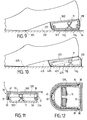
- Figure 7 is a side view with parts in section of a shoe type city shoe according to the invention.
- Figure 8 is a schematic perspective view of a detail of the shoe of Figure 6, on a larger scale.
- Figure 9 shows, similarly to Figure 7, an alternative embodiment of a city shoe.
- Figure 10 shows, similarly to Figure 9, another variant of a city shoe.
- Figure 11 is a longitudinal vertical section of the heel of another variant of a city shoe.
- FIG. 12 is a horizontal section, seen from above, of the heel of FIG. 11.
- Figure 13 is a schematic side view of another alternative embodiment of the shoe.
- the upper 9 of the shoe which envelops the foot F of the user, has its lower edges fixed on the periphery of the plate 2 and, towards the front, on the upper edge of the part 6.
- the assembly of the plate 2 and the front part 6 of the sole is covered by an inner sole 10 of reduced thickness, relatively soft, extending over the entire length of the shoe, so that the foot of the user does not feel any roughness of the junction zones.
- the arms 12b, 13b are located at the outer ends of the springs 12, 13 and are mutually parallel while the arms 12a, 13a are located at the inner ends of the windings 12, 13, these two arms being parallel also.
- the outer arms 12b , 13b are connected, at their outer radial ends, by a branch 15 parallel to the axis of the windings.
- the space 18 located between the plates 2 and 3 and included between the articulation zone 5 and the spring 11 is free of any material so that the plate 2 can be angularly debated, relative to the plate 3, by oscillation around the articulation zone 5 during variations of the useful height H of the spring.
- This useful height H is equal to the distance between the support plane of the branch 15 and the legs 16 a , 16 b and the plane parallel to this support plane tangent to the outside of the windings 12 , 13.
- the space 18 a located behind the spring 11 is also free of any material.
- the length of the lever arm d is substantially proportional to sin AT 2 .
- the plates 2 and 3 preferably have a U-shaped cross section turning their concavity towards each other.
- the concavity of the section of the upper plate 2 is turned downwards and the wings 21, 22 of this section, which are substantially vertical, are engaged between the wings 23, 24, facing upwards of the lower plate 3.
- the lower edge of the wings 21, 22 is located below the upper edge of the wings 23, 24.
- the torsion spring 11 of the invention occupies almost the entire width of the heel of the shoe, which contributes to good lateral stability, the axis of the winding being placed horizontally. In the case of conventional compression springs, several springs would be necessary.
- the lateral wings 104, 105 of the upper plate have, at their front end, an ear such as 27 framing a notch provided in the front edge of the upper plate 102.
- Each ear 27 has a hole serving bearing at the ends of axis 26.
- the lower plate 103 comprises a cylindrical sleeve 28 forming its front transverse edge, disposed between the ears 27.
- This sleeve 28 has a central bore crossed by the axis 26.
- a retaining tab 29 is provided at the rear of the plate 103 to cooperate with a stop provided on the rear face of the plate 102 and to keep the cassette 25 closed at rest, the spring 11 being prestressed by 1 mm.
- the assembly is such that even when the cassette is not stressed by a load, the side walls 104, 105 and 106, 107 overlap along a range.
- the plates 102 and 103 are made of a rigid plastic material, with a reduced coefficient of friction.
- This cassette 25 is intended to be slid, in the manner of a wedge, between an upper sole part and a lower sole part of a shoe, the upper and lower sole parts having a flexible zone at the metatarsus of the user's foot, area in which the hinge pin 26 of the cassette will be located.
- the lower and upper sole portions of the shoe are connected at their periphery by a sort of bellows similar to the bellows 19 of FIG. 1.
- the fixing of this bellows to the outer edges of the lower and upper sole portions can be removably provided so that the cassette 25 can be replaced by another cassette of the same type but whose spring has a different rigidity.
- the cassette can be put in place from below or from inside the shoe.
- the plates 102, 103 of the cassette are rigid, it is however possible to remove the rigid plates 2 and 3 from the sole of the shoe; in such a case, the upper sole part and the lower sole part are made entirely of a flexible material.
- a shoe fitted with such a cassette functions as explained above, and has the same advantages as those mentioned in connection with FIGS. 1 to 3.
- a shoe C according to the invention can be of the city shoe type with a prominent heel 30, protruding downwards while the sole 201, flexible in particular in the area 205 located under the metatarsus away from the ground from this area to the upper level of the heel at the back. There is therefore a free space 218 between the articulation zone 205 and the heel.
- the walls 222 and 224 are arranged to allow sufficient freedom in vertical translation while remaining engaged with one another when no load is exerted on the heel of the shoe.
- Figure 9 shows an alternative embodiment of the city shoe of Figure 7.
- the rigid upper plate 302 is limited by a rim 331 which surrounds a rim 34 of the lower plate 303.
- the rims 331 and 34 in their part transverse, have a shape curved, cylindrical, the horizontal axis of which is in the vicinity of the flexion region 305 of the sole.
- the spring 11 is housed between the plates 302, 303, the extent of which is limited to the area of the heel. There is a free space 318 between the zone 305 and the heel, so that the foot is not in too great contact on the front of the cassette.
- a sort of bellows 319 surrounds all of the plates 302, 303.
- FIG. 10 illustrates a variant of a city shoe comprising, housed in the heel, a cassette 425, similar to the cassette of FIG. 5, but of shorter length.
- the hinge pin 426 is located in the region of the front edge of the heel, the spring 11 being towards the rear.
- the cassette 425 is disposed between an upper plate 402 and a rigid lower plate 403.
- the assembly is surrounded by a sort of bellows 419. We find the flexion zone 405 at the level of the metatarsus and the free space 418.
- Figures 11 and 12 illustrate another alternative embodiment of the heel of a shoe.
- the rigid upper plate 502 is placed against the upper wall 35 of an envelope 36 integral with the sole and comprising a vertical peripheral wall 37 directed downwards.
- the plate 502 is provided with a vertical rim 531 on its contour, with the exception of its front transverse edge.
- the bottom plate 503 rigid, made of hard material like the plate 502, forms a sort of overturned cover with its rim 534 turned upwards, situated inside the wall 37 and the rim 531.
- the plate 503 can move , substantially vertically, relative to the plate 502.
- a stud 38 is provided projecting on each side, at the front and at the top of the longitudinal parts of the rim 534.
- Each stud 38 is received in a vertical groove 39 provided on the internal wall rim 534, and closed down.
- the plate 503 has at the rear, at the top of its rim, a lug 40 projecting rearwards, also received in a groove or window 41, closed downwards, from the rim 534.
- the spring 11 is arranged between the plates 502 and 503 in a manner similar to that described above.
- FIG. 13 shows a shoe whose sole has a cassette 625 a similar to the cassette 25 in FIG. 6, but moreover short length, located in front of the metatarsus of the user's foot and arranged in the opposite direction.
- the edge of the cassette 625 a is located slightly in front of the metatarsus, while the spring of the cassette 625 a is located under the toe of the shoe.
- the vertical elastic stroke of the spring of the cassette 625 a is smaller than that of the spring associated with the heel; this stroke is, for example, 3 or 4 mm.
- This cassette 625 a can be combined with a second cassette 625 b , arranged like the cassette 25 in FIGS. 5 and 6, that is to say with its edge forwards and its spring under the heel.
- the cassette spring 625 b has a travel of 6 to 7 mm.
- the cassette 625 a can be combined with a rear sole part similar to that of FIG. 1.
- a shoe according to the invention remains simple to manufacture while ensuring good shock absorption of the heel on the ground with an optimal restitution of the energy stored during the impact.
- the friction between the foot and the upper of the shoe, in particular at the heel, is eliminated despite the elasticity introduced at the heel.
Landscapes
- Footwear And Its Accessory, Manufacturing Method And Apparatuses (AREA)
Applications Claiming Priority (2)
| Application Number | Priority Date | Filing Date | Title |
|---|---|---|---|
| FR9200644A FR2686233A1 (fr) | 1992-01-22 | 1992-01-22 | Chaussure, en particulier chaussure de sport, comportant au moins un ressort dispose dans la semelle, cassette et ressort pour une telle chaussure. |
| FR9200644 | 1992-01-22 |
Publications (2)
| Publication Number | Publication Date |
|---|---|
| EP0552994A1 true EP0552994A1 (de) | 1993-07-28 |
| EP0552994B1 EP0552994B1 (de) | 1996-07-31 |
Family
ID=9425867
Family Applications (1)
| Application Number | Title | Priority Date | Filing Date |
|---|---|---|---|
| EP93400006A Expired - Lifetime EP0552994B1 (de) | 1992-01-22 | 1993-01-05 | Schuh, insbesondere Sportschuh, mit mindestens einer Feder in der Sohle, Kassette und Feder für einen solchen Schuh |
Country Status (6)
| Country | Link |
|---|---|
| US (1) | US5282325A (de) |
| EP (1) | EP0552994B1 (de) |
| JP (1) | JP3567218B2 (de) |
| DE (1) | DE69303833T2 (de) |
| ES (1) | ES2090894T3 (de) |
| FR (1) | FR2686233A1 (de) |
Cited By (10)
| Publication number | Priority date | Publication date | Assignee | Title |
|---|---|---|---|---|
| DE4339107A1 (de) * | 1993-11-16 | 1995-05-18 | Engros Schuhhaus Ag | Schuhsohle |
| WO1995013719A1 (de) * | 1993-11-16 | 1995-05-26 | Engros-Schuhhaus Ag | Schuhsohle |
| FR2729546A1 (fr) * | 1995-01-25 | 1996-07-26 | Bozion Jean | Chaussure, en particulier chaussure de sport, comportant un insert elastique restitueur d'energie |
| FR2748372A1 (fr) * | 1996-05-13 | 1997-11-14 | Paradis Frederic | Chaussure equipee d'un dispositif elastique d'amortissement des chocs |
| WO1998047400A1 (en) * | 1997-04-22 | 1998-10-29 | Pogacar Rado | Elastic footwear heel |
| WO2010117966A1 (en) * | 2009-04-10 | 2010-10-14 | Athletic Propulsion Labs LLC | Shoes, devices for shoes, and methods of using shoes |
| US8286372B2 (en) | 2008-02-29 | 2012-10-16 | Mark Rudolfovich Shirokikh | Footwear with energy accumulation |
| CN104544723A (zh) * | 2015-01-04 | 2015-04-29 | 李宁体育(上海)有限公司 | 分段式减震装置 |
| EP3270728A4 (de) * | 2016-02-19 | 2018-05-23 | Zhejiang Geely Holding Group Co., Ltd. | Sole gegen verstauchung und mit stossdämpfung und schuhwerk |
| US10085514B2 (en) | 2009-04-10 | 2018-10-02 | Athletic Propulsion Labs LLC | Shoes, devices for shoes, and methods of using shoes |
Families Citing this family (76)
| Publication number | Priority date | Publication date | Assignee | Title |
|---|---|---|---|---|
| US5435079A (en) * | 1993-12-20 | 1995-07-25 | Gallegos; Alvaro Z. | Spring athletic shoe |
| USD434548S (en) * | 1994-06-14 | 2000-12-05 | Gallegos Alvaro Z | Shoe with spring |
| US5513448A (en) * | 1994-07-01 | 1996-05-07 | Lyons; Levert | Athletic shoe with compression indicators and replaceable spring cassette |
| IT1282498B1 (it) * | 1995-11-15 | 1998-03-23 | Diadora Spa | Supporto di stabilita', particolarmente per il controllo della pronazione in scarpe sportive. |
| USD384192S (en) * | 1995-12-15 | 1997-09-30 | Frank Hsieh | Bouncing shoe |
| US5797198A (en) * | 1996-06-19 | 1998-08-25 | Pomerantz; David B. | Adjustable shock absorbing device for shoe |
| US5755144A (en) * | 1996-08-26 | 1998-05-26 | Shimano, Inc. | Low profile bicycle pedal with top and bottom side clamping arrangements |
| US5778739A (en) * | 1996-08-26 | 1998-07-14 | Shimano, Inc. | Bicycle pedal with gap adjusting mechanism |
| US5727429A (en) * | 1996-08-26 | 1998-03-17 | Shimano, Inc. | Low profile bicycle pedal and cleat assembly |
| US5743028A (en) * | 1996-10-03 | 1998-04-28 | Lombardino; Thomas D. | Spring-air shock absorbtion and energy return device for shoes |
| US5701685A (en) * | 1997-01-23 | 1997-12-30 | Mariner J. Pezza | Triple-action, adjustable, rebound device |
| WO1998047579A1 (en) | 1997-04-18 | 1998-10-29 | The Burton Corporation | An interface for engaging a snowboard boot to a binding |
| US6553692B1 (en) * | 1998-07-08 | 2003-04-29 | Gary G. Pipenger | Shock absorption mechanism for shoes |
| US7063336B2 (en) * | 1999-04-01 | 2006-06-20 | Heeling Sports Limited | External wheeled heeling apparatus and method |
| ES2245524B1 (es) | 1999-04-01 | 2007-03-16 | Heeling Sports Limited | Aparato y metodo de talonaje. |
| US20010042320A1 (en) * | 1999-05-11 | 2001-11-22 | Lindqvist Wilhelm Ove | Shoe system with a resilient shoe insert |
| SE524081C2 (sv) * | 1999-05-11 | 2004-06-22 | Trackguard Hb | Anordning vid sko med elastiskt inlägg och metod att använda anordningen |
| IT1311662B1 (it) * | 1999-11-11 | 2002-03-14 | Benetton Spa | Struttura di calzatura. |
| US6601042B1 (en) | 2000-03-10 | 2003-07-29 | Robert M. Lyden | Customized article of footwear and method of conducting retail and internet business |
| US6449878B1 (en) | 2000-03-10 | 2002-09-17 | Robert M. Lyden | Article of footwear having a spring element and selectively removable components |
| US7752775B2 (en) | 2000-03-10 | 2010-07-13 | Lyden Robert M | Footwear with removable lasting board and cleats |
| CA2330847C (en) * | 2001-01-12 | 2007-11-13 | Bauer Nike Hockey Inc. | In-line roller skate |
| US6457261B1 (en) | 2001-01-22 | 2002-10-01 | Ll International Shoe Company, Inc. | Shock absorbing midsole for an athletic shoe |
| TW491031U (en) * | 2001-03-20 | 2002-06-11 | Lien Year Entpr Corp | Shoes with elastic heels |
| US6860034B2 (en) * | 2001-04-09 | 2005-03-01 | Orthopedic Design | Energy return sole for footwear |
| US6879885B2 (en) * | 2001-11-16 | 2005-04-12 | Goodrich Pump & Engine Control Systems, Inc. | Rotor torque predictor |
| US6901686B2 (en) * | 2001-12-07 | 2005-06-07 | Riccardo W. Hayes | Devices and systems for dynamic foot support |
| US6684531B2 (en) | 2001-12-27 | 2004-02-03 | Brian G. Rennex | Spring space shoe |
| US6848201B2 (en) * | 2002-02-01 | 2005-02-01 | Heeling Sports Limited | Shock absorption system for a sole |
| WO2003063628A1 (en) * | 2002-02-01 | 2003-08-07 | Heeling Sports Limited | Grind rail apparatus |
| US7401419B2 (en) * | 2002-07-31 | 2008-07-22 | Adidas International Marketing B.V, | Structural element for a shoe sole |
| DE102005006267B3 (de) * | 2005-02-11 | 2006-03-16 | Adidas International Marketing B.V. | Schuhsohle und Schuh |
| US7290354B2 (en) | 2002-11-21 | 2007-11-06 | Stephen Perenich | Shoe suspension system |
| US7905033B1 (en) * | 2002-11-21 | 2011-03-15 | Stephen Perenich | Energy-return shoe system |
| US7950166B1 (en) | 2002-11-21 | 2011-05-31 | Stephen Perenich | Simplified energy-return shoe system |
| US6928756B1 (en) * | 2003-03-03 | 2005-08-16 | Richard Haynes | Jump assisting spring heel shoe |
| US8056262B2 (en) * | 2003-10-08 | 2011-11-15 | Trackguard Ab | Shoe system with a resilient shoe insert |
| US20050166422A1 (en) * | 2004-02-04 | 2005-08-04 | Puma Aktiengesellschaft Rudolf Dassler Sport | Shoe with an articulated spring-loaded outsole |
| US7334351B2 (en) * | 2004-06-07 | 2008-02-26 | Energy Management Athletics, Llc | Shoe apparatus with improved efficiency |
| ES2545261T3 (es) * | 2004-08-04 | 2015-09-09 | Heeling Sports Limited | Aparato y procedimiento de transporte motorizado |
| WO2006032014A2 (en) * | 2004-09-14 | 2006-03-23 | Tripod, L.L.C. | Sole unit for footwear and footwear incorporating same |
| WO2006129392A1 (ja) * | 2005-05-30 | 2006-12-07 | Mizuno Corporation | シューズのソール構造体 |
| US20070101617A1 (en) * | 2005-11-10 | 2007-05-10 | Fila Luxembourg S.A.R.L. | Footwear sole assembly having spring mechanism |
| US7415882B2 (en) * | 2005-12-19 | 2008-08-26 | The Boeing Company | Methods and systems for inspection of composite assemblies |
| ITTV20060213A1 (it) * | 2006-11-28 | 2008-05-29 | Tecnica Spa | Calzatura sportiva per sport di scivolamento |
| DE102006059658B3 (de) * | 2006-12-18 | 2008-03-27 | Adidas International Marketing B.V. | Schuh |
| US20120110871A1 (en) * | 2007-02-13 | 2012-05-10 | Alexander Elnekaveh | Resilient Shoe With Pivoting Sole |
| EP2187775B1 (de) * | 2007-09-06 | 2018-07-18 | Powerdisk Development Ltd. | Energiespeicherung und rückholfeder |
| KR100887625B1 (ko) | 2007-12-12 | 2009-03-10 | 황영순 | 충격흡수와 반발탄성이 이루어지는 탄성바닥재 및 이를구비한 신발 |
| DE202008004735U1 (de) | 2008-04-07 | 2009-10-29 | Head Technology Gmbh | Sportschuh, insbesondere Tennisschuh |
| KR20110006700A (ko) * | 2008-05-01 | 2011-01-20 | 플란티가 테크놀로지스 인크. | 깔창 서스펜션 시스템이 내장된 신발 어셈블리 |
| DE202009004313U1 (de) | 2009-03-26 | 2009-06-25 | Solor Schuhforschung Und Entwicklung-Gmbh | Orthopädischer Schuh |
| US20100251571A1 (en) * | 2009-04-07 | 2010-10-07 | Steven Paul Woodard | Shoe suspension system |
| US8112905B2 (en) | 2009-04-10 | 2012-02-14 | Athletic Propulsion Labs LLC | Forefoot catapult for athletic shoes |
| US8347526B2 (en) * | 2009-04-10 | 2013-01-08 | Athletic Propulsion Labs LLC | Shoes, devices for shoes, and methods of using shoes |
| US20120055048A1 (en) * | 2009-04-24 | 2012-03-08 | Veronica HAUPT | Heel for a shoe |
| CA2766455C (en) | 2009-06-22 | 2019-03-26 | Powerdisk Development Ltd. | Springs for shoes |
| US20110057400A1 (en) * | 2009-09-09 | 2011-03-10 | Ryan Daniel Wills | Wheeled platform apparatus and method for use with wheeled footwear |
| FR2972906B1 (fr) * | 2011-03-25 | 2014-05-16 | Gecis | Chaussure a amorti et propulsion ameliores |
| FR2974308A1 (fr) * | 2011-04-21 | 2012-10-26 | Patrice Jean Andre Cornillon | Dispositif permettant la fixation d'un ressort aidant a la montee et a l'avancee pour planches de glisse (ski alpinisme, ski de randonnee, ski de fond) ou de marche (raquettes a neige) |
| US20120324760A1 (en) * | 2011-04-27 | 2012-12-27 | Ochoa Adam A | Footwear with heel based arcuate panel-shaped impact absorbing resilient concealed tongue |
| US9032646B2 (en) | 2011-11-23 | 2015-05-19 | Stephen Perenich | Energy-return shoe system |
| CN104159466B (zh) * | 2012-03-08 | 2016-10-12 | 思达科技有限公司 | 鞋类制品、鞋类制品中使用的鞋底和泵装置及其制造方法 |
| US10945485B2 (en) | 2012-08-03 | 2021-03-16 | Heeling Sports Limited | Heeling apparatus |
| US10849387B2 (en) | 2012-09-20 | 2020-12-01 | Nike, Inc. | Sole structures and articles of footwear having plate moderated fluid-filled bladders and/or foam type impact force attenuation members |
| US10856612B2 (en) | 2012-09-20 | 2020-12-08 | Nike, Inc. | Sole structures and articles of footwear having plate moderated fluid-filled bladders and/or foam type impact force attenuation members |
| US9456658B2 (en) | 2012-09-20 | 2016-10-04 | Nike, Inc. | Sole structures and articles of footwear having plate moderated fluid-filled bladders and/or foam type impact force attenuation members |
| MX350919B (es) * | 2013-05-23 | 2017-09-22 | Zavala Riva Palacio Manuel | Zapato con amortiguamiento en el tacón. |
| US9538813B1 (en) | 2014-08-20 | 2017-01-10 | Akervall Technologies, Inc. | Energy absorbing elements for footwear and method of use |
| FR3034986B1 (fr) | 2015-04-16 | 2021-05-21 | Aplinov | Dispositif d'assistance aux deplacements |
| DE102015109369B4 (de) | 2015-06-12 | 2019-03-07 | Creation & Focus Design GmbH | Feder-Dämpfer-Einheiten für Schuhwerk |
| CA3012492A1 (en) * | 2016-01-25 | 2017-08-03 | B-Temia Inc. | Load bearing assistance apparatus for lower extremity orthotic or prosthetic devices |
| CN107518511B (zh) * | 2017-09-21 | 2023-09-15 | 安踏(中国)有限公司 | 一种用于鞋体的缓震装置、鞋底及运动鞋 |
| US11484092B2 (en) | 2020-07-15 | 2022-11-01 | Athletic Propulsion Labs LLC | Shoes, devices for shoes, and methods of using shoes |
| CN112293850A (zh) * | 2020-10-16 | 2021-02-02 | 国网山东省电力公司嘉祥县供电公司 | 一种安全绝缘鞋套及试验装置 |
| US11576465B2 (en) | 2021-05-18 | 2023-02-14 | Athletic Propulsion Labs LLC | Shoes, devices for shoes, and methods of using shoes |
Citations (4)
| Publication number | Priority date | Publication date | Assignee | Title |
|---|---|---|---|---|
| DE16130C (de) * | E. HERZOG in Klausenburg, Siebenbürgen | Elastischer Absatz | ||
| CH228630A (de) * | 1942-11-25 | 1943-09-15 | Weller Karl | Elastische Schuhsohle, speziell für Zoccoli. |
| US3886674A (en) * | 1972-11-23 | 1975-06-03 | Rafael Saurina Pavia | Article of footwear |
| US4843737A (en) * | 1987-10-13 | 1989-07-04 | Vorderer Thomas W | Energy return spring shoe construction |
Family Cites Families (17)
| Publication number | Priority date | Publication date | Assignee | Title |
|---|---|---|---|---|
| US357062A (en) * | 1887-02-01 | Spring-heel for boots or shoes | ||
| US581661A (en) * | 1897-04-27 | Birger iieftye | ||
| US980657A (en) * | 1909-05-19 | 1911-01-03 | Justin S Meacham | Spring-heel for shoes. |
| US993279A (en) * | 1909-06-19 | 1911-05-23 | Gilmer Bray | Heel for boots and shoes. |
| US1328816A (en) * | 1919-04-30 | 1920-01-27 | William W Brown | Shock-absorbing heel |
| US1403970A (en) * | 1921-03-15 | 1922-01-17 | Lioy Paul | Heel cushion |
| US1469920A (en) * | 1922-09-21 | 1923-10-09 | Dutchak John | Spring heel |
| FR701729A (fr) * | 1930-05-21 | 1931-03-21 | Dispositif amortisseur permettant l'utilisation des chocs se produisant en particulier pendant la marche | |
| FR909691A (fr) * | 1945-03-16 | 1946-05-15 | Semelle articulée et élastique pour chaussures de tous genres | |
| US2475092A (en) * | 1947-05-23 | 1949-07-05 | William B Harrell | Bouncing skate |
| US2545519A (en) * | 1950-03-27 | 1951-03-20 | John D Kells | Shoe heel |
| FR2507066A1 (fr) * | 1981-06-09 | 1982-12-10 | Barbeau Jacques | Dispositif elastique a inclure dans une semelle |
| US4492046A (en) * | 1983-06-01 | 1985-01-08 | Ghenz Kosova | Running shoe |
| US4756095A (en) * | 1986-06-23 | 1988-07-12 | Nikola Lakic | Footwarmer for shoe |
| US4771554A (en) * | 1987-04-17 | 1988-09-20 | Foot-Joy, Inc. | Heel shoe construction |
| US4894934A (en) * | 1989-01-23 | 1990-01-23 | Illustrato Vito J | Rebound heel device |
| US5159767A (en) * | 1990-06-11 | 1992-11-03 | Allen Don T | Orthopedic stabilizer attachment |
-
1992
- 1992-01-22 FR FR9200644A patent/FR2686233A1/fr active Granted
- 1992-10-19 US US07/962,731 patent/US5282325A/en not_active Expired - Lifetime
-
1993
- 1993-01-05 DE DE69303833T patent/DE69303833T2/de not_active Expired - Lifetime
- 1993-01-05 EP EP93400006A patent/EP0552994B1/de not_active Expired - Lifetime
- 1993-01-05 ES ES93400006T patent/ES2090894T3/es not_active Expired - Lifetime
- 1993-01-22 JP JP00957993A patent/JP3567218B2/ja not_active Expired - Fee Related
Patent Citations (4)
| Publication number | Priority date | Publication date | Assignee | Title |
|---|---|---|---|---|
| DE16130C (de) * | E. HERZOG in Klausenburg, Siebenbürgen | Elastischer Absatz | ||
| CH228630A (de) * | 1942-11-25 | 1943-09-15 | Weller Karl | Elastische Schuhsohle, speziell für Zoccoli. |
| US3886674A (en) * | 1972-11-23 | 1975-06-03 | Rafael Saurina Pavia | Article of footwear |
| US4843737A (en) * | 1987-10-13 | 1989-07-04 | Vorderer Thomas W | Energy return spring shoe construction |
Cited By (13)
| Publication number | Priority date | Publication date | Assignee | Title |
|---|---|---|---|---|
| WO1995013719A1 (de) * | 1993-11-16 | 1995-05-26 | Engros-Schuhhaus Ag | Schuhsohle |
| DE4339107A1 (de) * | 1993-11-16 | 1995-05-18 | Engros Schuhhaus Ag | Schuhsohle |
| FR2729546A1 (fr) * | 1995-01-25 | 1996-07-26 | Bozion Jean | Chaussure, en particulier chaussure de sport, comportant un insert elastique restitueur d'energie |
| FR2748372A1 (fr) * | 1996-05-13 | 1997-11-14 | Paradis Frederic | Chaussure equipee d'un dispositif elastique d'amortissement des chocs |
| WO1997042845A1 (fr) * | 1996-05-13 | 1997-11-20 | Paradis Frederic | Chaussure equipee d'un dispositif elastique d'amortissement des chocs |
| WO1998047400A1 (en) * | 1997-04-22 | 1998-10-29 | Pogacar Rado | Elastic footwear heel |
| US8286372B2 (en) | 2008-02-29 | 2012-10-16 | Mark Rudolfovich Shirokikh | Footwear with energy accumulation |
| WO2010117966A1 (en) * | 2009-04-10 | 2010-10-14 | Athletic Propulsion Labs LLC | Shoes, devices for shoes, and methods of using shoes |
| US10085514B2 (en) | 2009-04-10 | 2018-10-02 | Athletic Propulsion Labs LLC | Shoes, devices for shoes, and methods of using shoes |
| CN104544723A (zh) * | 2015-01-04 | 2015-04-29 | 李宁体育(上海)有限公司 | 分段式减震装置 |
| CN104544723B (zh) * | 2015-01-04 | 2016-06-22 | 李宁体育(上海)有限公司 | 分段式减震装置 |
| EP3270728A4 (de) * | 2016-02-19 | 2018-05-23 | Zhejiang Geely Holding Group Co., Ltd. | Sole gegen verstauchung und mit stossdämpfung und schuhwerk |
| US10524537B2 (en) | 2016-02-19 | 2020-01-07 | Zhejiang Geely Holding Group Co., Ltd. | Anti-sprain and shock-absorbing balance sole and footgear |
Also Published As
| Publication number | Publication date |
|---|---|
| DE69303833D1 (de) | 1996-09-05 |
| US5282325A (en) | 1994-02-01 |
| FR2686233B1 (de) | 1995-04-28 |
| EP0552994B1 (de) | 1996-07-31 |
| JPH05293001A (ja) | 1993-11-09 |
| DE69303833T2 (de) | 1997-02-06 |
| FR2686233A1 (fr) | 1993-07-23 |
| ES2090894T3 (es) | 1996-10-16 |
| JP3567218B2 (ja) | 2004-09-22 |
Similar Documents
| Publication | Publication Date | Title |
|---|---|---|
| EP0552994B1 (de) | Schuh, insbesondere Sportschuh, mit mindestens einer Feder in der Sohle, Kassette und Feder für einen solchen Schuh | |
| EP0991334B1 (de) | Schuh mit verformbarer besohlung | |
| EP1100349B1 (de) | Schuhsohle | |
| EP2198729B1 (de) | Schuh mit verbessertem Schuhboden | |
| CH672399A5 (de) | ||
| WO2005013746A1 (fr) | Semelle plantaire a amortissement selectif | |
| FR2851130A1 (fr) | Semelage de chaussure | |
| EP0056774B1 (de) | Skischuh | |
| FR2768938A1 (fr) | Raquette a neige | |
| EP1765232B1 (de) | Schuhfersenschale, und schuh mit entsprechender fersenschale versehen | |
| EP1229808A1 (de) | Schutzschuhwerk, wie ein stiefel oder dergleichen | |
| EP4349201A1 (de) | Sohle eines schuhs | |
| WO2019141735A1 (fr) | Semelle pour chaussure de sport comprenant une ou plusieurs figures de déformation | |
| EP1302119A1 (de) | Sportschuh | |
| EP3232846B1 (de) | Aussensohle für schuhwerk mit dämpfungsstollen | |
| EP0401108B1 (de) | Sportschuhsohle, die den Absprung und die Landungseigenschaften verbessert | |
| EP3880024A1 (de) | Sportschuh mit optimierter sohle | |
| FR2788946A1 (fr) | Chaussure de ski | |
| WO2005102827A1 (fr) | Platine de liaison rapide d'une chaussure de cycliste sur une pedale automatique de cycle, et pedale de cycle automatique adaptee a une telle platine | |
| EP2959949B1 (de) | Vorrichtung zur aufnahme eines schuhs auf einem gleitgerät | |
| WO2003088777A2 (fr) | Semelage de chaussure | |
| FR2783175A1 (fr) | Dispositif pour accelerer le deroulement du pas durant la marche | |
| FR3114486A1 (fr) | Semelle intermédiaire pour article chaussant et article chaussant correspondant | |
| FR2934758A1 (fr) | Structure pour une semelle de chaussure, en particulier une chaussure de sport | |
| FR2661321A1 (fr) | Chaussure de sport a semelle d'usure a flexion transversale amelioree. |
Legal Events
| Date | Code | Title | Description |
|---|---|---|---|
| PUAI | Public reference made under article 153(3) epc to a published international application that has entered the european phase |
Free format text: ORIGINAL CODE: 0009012 |
|
| AK | Designated contracting states |
Kind code of ref document: A1 Designated state(s): CH DE ES GB IT LI |
|
| 17P | Request for examination filed |
Effective date: 19930923 |
|
| 17Q | First examination report despatched |
Effective date: 19941108 |
|
| GRAH | Despatch of communication of intention to grant a patent |
Free format text: ORIGINAL CODE: EPIDOS IGRA |
|
| GRAH | Despatch of communication of intention to grant a patent |
Free format text: ORIGINAL CODE: EPIDOS IGRA |
|
| RAP1 | Party data changed (applicant data changed or rights of an application transferred) |
Owner name: BEYL, SUZANNE |
|
| RIN1 | Information on inventor provided before grant (corrected) |
Inventor name: BEYL, JEAN |
|
| GRAA | (expected) grant |
Free format text: ORIGINAL CODE: 0009210 |
|
| AK | Designated contracting states |
Kind code of ref document: B1 Designated state(s): CH DE ES GB IT LI |
|
| REG | Reference to a national code |
Ref country code: CH Ref legal event code: NV Representative=s name: KIRKER & CIE SA |
|
| REF | Corresponds to: |
Ref document number: 69303833 Country of ref document: DE Date of ref document: 19960905 |
|
| GBT | Gb: translation of ep patent filed (gb section 77(6)(a)/1977) |
Effective date: 19960904 |
|
| ITF | It: translation for a ep patent filed | ||
| REG | Reference to a national code |
Ref country code: ES Ref legal event code: FG2A Ref document number: 2090894 Country of ref document: ES Kind code of ref document: T3 |
|
| REG | Reference to a national code |
Ref country code: ES Ref legal event code: FG2A Ref document number: 2090894 Country of ref document: ES Kind code of ref document: T3 |
|
| PLBE | No opposition filed within time limit |
Free format text: ORIGINAL CODE: 0009261 |
|
| STAA | Information on the status of an ep patent application or granted ep patent |
Free format text: STATUS: NO OPPOSITION FILED WITHIN TIME LIMIT |
|
| 26N | No opposition filed | ||
| REG | Reference to a national code |
Ref country code: GB Ref legal event code: IF02 |
|
| PGFP | Annual fee paid to national office [announced via postgrant information from national office to epo] |
Ref country code: IT Payment date: 20110129 Year of fee payment: 19 Ref country code: DE Payment date: 20110210 Year of fee payment: 19 Ref country code: CH Payment date: 20110216 Year of fee payment: 19 |
|
| PGFP | Annual fee paid to national office [announced via postgrant information from national office to epo] |
Ref country code: ES Payment date: 20110228 Year of fee payment: 19 Ref country code: GB Payment date: 20110222 Year of fee payment: 19 |
|
| REG | Reference to a national code |
Ref country code: CH Ref legal event code: PL |
|
| GBPC | Gb: european patent ceased through non-payment of renewal fee |
Effective date: 20120105 |
|
| PG25 | Lapsed in a contracting state [announced via postgrant information from national office to epo] |
Ref country code: DE Free format text: LAPSE BECAUSE OF NON-PAYMENT OF DUE FEES Effective date: 20120801 Ref country code: LI Free format text: LAPSE BECAUSE OF NON-PAYMENT OF DUE FEES Effective date: 20120131 Ref country code: GB Free format text: LAPSE BECAUSE OF NON-PAYMENT OF DUE FEES Effective date: 20120105 Ref country code: CH Free format text: LAPSE BECAUSE OF NON-PAYMENT OF DUE FEES Effective date: 20120131 |
|
| REG | Reference to a national code |
Ref country code: DE Ref legal event code: R119 Ref document number: 69303833 Country of ref document: DE Effective date: 20120801 |
|
| PG25 | Lapsed in a contracting state [announced via postgrant information from national office to epo] |
Ref country code: IT Free format text: LAPSE BECAUSE OF NON-PAYMENT OF DUE FEES Effective date: 20120105 |
|
| REG | Reference to a national code |
Ref country code: ES Ref legal event code: FD2A Effective date: 20130705 |
|
| PG25 | Lapsed in a contracting state [announced via postgrant information from national office to epo] |
Ref country code: ES Free format text: LAPSE BECAUSE OF NON-PAYMENT OF DUE FEES Effective date: 20120106 |