EP0552501A2 - Kokille zum Stranggiessen von Stahlband - Google Patents
Kokille zum Stranggiessen von Stahlband Download PDFInfo
- Publication number
- EP0552501A2 EP0552501A2 EP92122119A EP92122119A EP0552501A2 EP 0552501 A2 EP0552501 A2 EP 0552501A2 EP 92122119 A EP92122119 A EP 92122119A EP 92122119 A EP92122119 A EP 92122119A EP 0552501 A2 EP0552501 A2 EP 0552501A2
- Authority
- EP
- European Patent Office
- Prior art keywords
- side walls
- pouring area
- radii
- steel strip
- mold
- Prior art date
- Legal status (The legal status is an assumption and is not a legal conclusion. Google has not performed a legal analysis and makes no representation as to the accuracy of the status listed.)
- Granted
Links
- 229910000831 Steel Inorganic materials 0.000 title claims abstract description 7
- 239000010959 steel Substances 0.000 title claims abstract description 7
- 238000009749 continuous casting Methods 0.000 title claims abstract description 4
- 238000005266 casting Methods 0.000 claims abstract description 10
- 238000005452 bending Methods 0.000 abstract description 2
- 229910001208 Crucible steel Inorganic materials 0.000 description 4
- 238000006073 displacement reaction Methods 0.000 description 2
Images


Classifications
-
- B—PERFORMING OPERATIONS; TRANSPORTING
- B22—CASTING; POWDER METALLURGY
- B22D—CASTING OF METALS; CASTING OF OTHER SUBSTANCES BY THE SAME PROCESSES OR DEVICES
- B22D11/00—Continuous casting of metals, i.e. casting in indefinite lengths
- B22D11/04—Continuous casting of metals, i.e. casting in indefinite lengths into open-ended moulds
- B22D11/0408—Moulds for casting thin slabs
Definitions
- the invention relates to a mold for the continuous casting of steel strip or thin slabs with cooled broad side walls and narrow side walls, the wide side walls forming a funnel-shaped pouring area, which is reduced to the narrow side walls and in the casting direction to the format of the cast strip and on each broad side wall the curvature of the pouring area by lateral Circular arcs and central arcs connected to them at tangent points are determined, the radii of which gradually increase with their distance from the upper edge of the mold.
- the curvature of the broad side walls forming the pouring area is designed in the form of an arc of a circle such that both the radii of the lateral arcs and the radii of the central arcs gradually increase in the direction of the strand.
- the strand shell that forms immediately below the casting level is continuously deformed up to the end of the pouring area due to the change in radius of the arcs. The deformation increases the friction between the strand shell and the broad side wall and thus the tensile stress on the strand shell.
- EP-B1 02 68 910 discloses a mold with an enlarged pouring area, a first section of the pouring area being used to reduce the strain on the strand shell the broad side wall is parallel-walled, resulting in opposite deformations.
- the object of the invention is to provide a mold of the type specified, the curvature of the broad side walls determined by an arc being designed in such a way that friction and wear on the broad side walls are reduced and the tensile and bending stress on the strand shell is reduced in such a way that the operational reliability of the casting process is increased and a flawless steel strip is produced.
- the invention is based on the idea of creating deformation-free arch areas on the broad side walls.
- the radii of the lateral arcs from the upper mold edge are constant in a portion of the pouring area which extends at least 100 mm down from the upper mold edge.
- a further enlargement of the deformation-free curvature areas is achieved in that the radii of the lateral arcs are the same over the entire height of the pouring area.
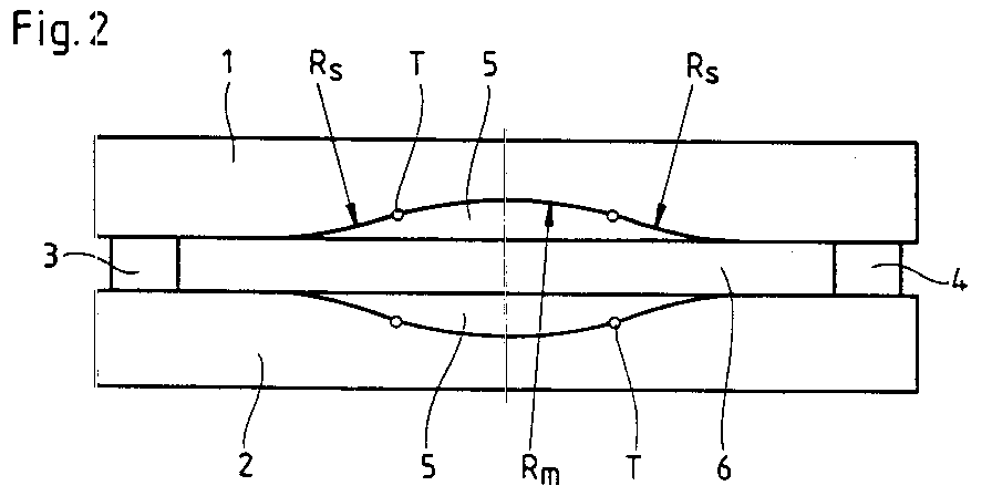
- a steel strip casting mold consists of two broad side walls 1, 2 and two narrow side walls 3, 4 arranged laterally between the broad side walls 1, 2.
- the wide side walls 1, 2 each form a pouring area 5 through an upper bulge, which leads to the narrow side walls 3 , 4 and in the casting direction to the thickness of the cast steel strip 6 is reduced.
- the shape of the pouring area 5 is determined by lateral arches and middle arches, the radii of curvature R s and R m of which increase uniformly in the casting direction.
- the tangent points T of successive arcs R s and R m form straight lines 7. Due to the successive enlargement of the radii R s and R m , the strand shell of the cast steel strip 6 is deformed on the entire surface of the pouring area 5.
- FIG 3 shows a side of a pouring area 8 shaped according to the invention with lateral and inner arches in the levels I, II, III.
- the radii R mI , R mII , R mIII of the middle arcs are evenly larger from top to bottom.
- the radii R sI and R sII of the lateral arches remain the same up to level II and increase evenly from level II to the end of the pouring area 8. This results in a lateral displacement of the tangent points T I , T II up to level II .
- kinked lines 9 are shown as the geometric location of the tangent points T I , T II , T III . In this way, a zone 10 is formed in which the strand shell of the cast steel strip 6 is advantageously not deformed.
- Fig. 5 shows a side of an alternatively shaped pouring area 11 with side and middle arches in the levels IV, V, VI.
- the radii R mIV , R mV , R mVI of the middle arches are evenly enlarged from top to bottom.
- the radii R sIV , R sV , R sVI of the side arches are the same across all levels IV, V, VI. This results in a lateral displacement of the tangent points T IV , T V , T VI over the entire height of the pouring area 11.
- lines 12 are shown as geometric locations of the tangent points T IV , T V T VI .
- the strand shell of the cast steel strip 6 is advantageously not deformed.
Landscapes
- Engineering & Computer Science (AREA)
- Mechanical Engineering (AREA)
- Continuous Casting (AREA)
Abstract
Description
- Die Erfindung betrifft eine Kokille zum Stranggießen von Stahlband oder Dünnbrammen mit gekühlten Breitseitenwänden und Schmalseitenwänden, wobei die Breitseitenwände einen trichterförmigen Eingießbereich bilden, der zu den Schmalseitenwänden und in Gießrichtung auf das Format des gegossenen Bandes reduziert ist und an jeder Breitseitenwand die Wölbung des Eingießbereichs durch seitliche Kreisbögen und an Tangentpunkten mit diesen verbundene mittlere Kreisbögen bestimmt ist, deren Radien mit ihrem Abstand von der Kokillenoberkante suksessive größer werden.
- Bei dieser durch die DE-A1 39 07 351 bekannten Kokille ist die den Eingießbereich bildende Wölbung der Breitseitenwände derart kreisbogenförmig gestaltet, daß sowohl die Radien der seitlichen Kreisbögen als auch die Radien der mittleren Kreisbögen in Stranglaufrichtung allmählich größer werden. An derartigen Wölbungen wird die sich unmittelbar unterhalb des Gießspiegels bildende Strangschale aufgrund der Radienänderung der Kreisbögen stetig bis zum Ende des Eingießbereichs verformt. Durch die Verformung wird die Reibung zwischen Strangschale und Breitseitenwand und damit die Zugbeanspruchung der Strangschale erhöht.
- Durch die EP-B1 02 68 910 ist eine Kokille mit erweitertem Eingießbereich bekannt, wobei zur Reduzierung der Strangschalenbelastung ein erster Abschnitt des Eingießbereichs der Breitseitenwand parallelwandig ist, wobei sich entgegengesetzte Verformungen ergeben.
- Aufgabe der Erfindung ist die Schaffung einer Kokille der angegebenen Gattung, wobei die durch Kreisbogen bestimmte Wölbung der Breitseitenwände derart gestaltet ist, daß Reibung und Verschleiß an den Breitseitenwänden vermindert und die Zug- und Biegebeanspruchung der Strangschale derart reduziert wird, daß die Betriebssicherheit des Gießvorganges erhöht und ein fehlerfreies Stahlband erzeugt wird.
- Der Erfindung liegt der Gedanke zugrunde, an den Breitseitenwänden verformungsfreie Wölbungsbereiche zu schaffen.
- Erfindungsgemäß wird vorgeschlagen, daß die Radien der seitlichen Kreisbögen von der Kokillenoberkante in einem mindestens 100 mm von der Kokillenoberkante abwärts reichenden Abschnitt des Eingießbereichs gleichbleibend sind.
- Dadurch wird erreicht, daß die noch dünne Strangschale unterhalb des Gießspiegels zu einem größeren Flächenanteil verformungsfrei geführt wird.
- Eine weitere Vergrößerung der verformungsfreien Wölbungsbereiche wird dadurch erreicht, daß die Radien der seitlichen Kreisbögen über die gesamte Höhe des Eingießbereichs gleich sind.
- In der Zeichnung sind Ausführungsbeispiele mit Merkmalen und Vorteilen der Erfindung dargestellt. Es Zeigen
- Fig. 1
- die Innenansicht einer bekannten Kokillenbreitseitenwand mit seitlich vorgeordneten Schmalseitenwänden,
- Fig. 2
- die Draufsicht einer Stahlbandgießkokille,
- Fig. 3
- eine Seite eines erfindungsgemäßen Eingießbereichs in Draufsicht,
- Fig. 4
- die Innenansicht einer gemäß Fig. 3 gestalteten Breitseitenwand,
- Fig. 5
- eine Seite eines alternativ gestalteten Eingießbereichs in Draufsicht
und - Fig. 6
- die Innenansicht einer gemäß Fig. 5 gestalteten Breitseitenwand.
- Eine Stahlbandgießkokille besteht gemäß den Figuren 1 und 2 aus zwei Breitseitenwänden 1, 2 und zwei seitlich zwischen den Breitseitenwänden 1, 2 angeordneten Schmalseitenwänden 3, 4. Die Breitseitenwänden 1, 2 bilden durch je eine obere Auswölbung einen Eingießbereich 5, der zu den Schmalseitenwänden 3, 4 und in Gießrichtung auf die Dicke des gegossenen Stahlbandes 6 reduziert ist.
- Die Form des Eingießbereichs 5 ist durch seitlichen Bögen und mittlere Bögen bestimmt, deren Krümmungsradien Rs und Rm in Gießrichtung gleichmäßig zunehmen. Bei dieser in Fig. 1 dargestellten bekannten Ausführung bilden die Tangentpunkte T aufeinanderfolgender Bögen Rs und Rm Geraden 7. Aufgrund der sukzessiven Vergrößerung der Radien Rs und Rm wird die Strangschale des gegossenen Stahlbandes 6 an der gesamte Fläche des Eingießbereichs 5 verformt.
- In Fig. 3 ist eine Seite eines erfindungsgemäß geformten Eingießbereichs 8 mit seitlichen und inneren Bögen in den Ebenen I, II, III dargestellt. Dabei werden die Radien RmI, RmII, RmIII der mittleren Bögen gleichmäßig von oben nach unten größer. Die Radien RsI und RsII der seitlichen Bögen bleiben bis zur Ebene II gleich und nehmen von der Ebene II bis zum Ende des Eingießbereichs 8 gleichmäßig zu. Daraus ergibt sich bis zur Ebene II eine Seitenverlagerung der Tangentpunkte TI, TII.
- In der Innenansicht gemäß Fig. 4 sind abgeknickte Linien 9 als geometrischer Ort der Tangentpunkte TI, TII, TIII dargestellt. Auf diese Weise wird eine Zone 10 gebildet, in der die Strangschale des gegossenen Stahlbandes 6 vorteilhaft nicht verformt wird.
- Fig. 5 zeigt eine Seite eines alternativ geformten Eingießbereichs 11 mit seitlichen und mittleren Bögen in den Ebenen IV, V, VI. Dabei sind die Radien RmIV, RmV, RmVI der mittleren Bögen gleichmäßig von oben nach unten vergrößert. Die Radien RsIV, RsV, RsVI der seitlichen Bögen sind über alle Ebenen IV, V, VI gleich. Daraus ergibt sich über die gesamte Höhe des Eingießbereichs 11 eine Seitenverlagerung der Tangentpunkte TIV, TV, TVI.
- In der Innenansicht gemäß Fig. 6 sind Linien 12 als geometrische Orte der Tangentpunkte TIV, TV TVI dargestellt. In den Zonen 13 des Eingießbereichs 11 wird die Strangschale des gegossenen Stahlbandes 6 vorteilhaft nicht verformt.
Claims (2)
- Kokille zum Stranggießen von Stahlband oder Dünnbrammen mit gekühlten Breitseitenwänden und Schmalseitenwänden, wobei die Breitseitenwände einen trichterförmigen Eingießbereich bilden, der zu den Schmalseitenwänden und in Gießrichtung auf das Format des gegossenen Bandes reduziert ist und an jeder Breitseitenwand die Wölbung des Eingießbereichs durch seitliche Kreisbögen und an Tangentpunkten mit diesen verbundene mittlere Kreisbögen bestimmt ist, deren Radien mit ihrem Abstand von der Kokillenoberkante suksessive größer werden,
dadurch gekennzeichnet,
daß die Radien (RsI - II) der seitlichen Kreisbögen von der Kokillenoberkante in einem mindestens 100 mm von der Kokillenoberkante abwärts reichenden Abschnitt (10) des Eingießbereichs (8) gleichbleibend sind. - Kokille nach Anspruch 1,
dadurch gekennzeichnet,
daß die Radien (RsIV - VI) der seitlichen Kreisbögen über die gesamte Höhe des Eingießbereichs (11) gleich sind.
Applications Claiming Priority (2)
| Application Number | Priority Date | Filing Date | Title |
|---|---|---|---|
| DE4201363 | 1992-01-20 | ||
| DE4201363A DE4201363C2 (de) | 1992-01-20 | 1992-01-20 | Kokille zum Stranggießen von Stahlband |
Publications (3)
| Publication Number | Publication Date |
|---|---|
| EP0552501A2 true EP0552501A2 (de) | 1993-07-28 |
| EP0552501A3 EP0552501A3 (de) | 1995-02-22 |
| EP0552501B1 EP0552501B1 (de) | 1997-05-14 |
Family
ID=6449855
Family Applications (1)
| Application Number | Title | Priority Date | Filing Date |
|---|---|---|---|
| EP92122119A Expired - Lifetime EP0552501B1 (de) | 1992-01-20 | 1992-12-30 | Kokille zum Stranggiessen von Stahlband |
Country Status (7)
| Country | Link |
|---|---|
| US (1) | US5311922A (de) |
| EP (1) | EP0552501B1 (de) |
| JP (1) | JP3140592B2 (de) |
| AT (1) | ATE152938T1 (de) |
| CA (1) | CA2087314A1 (de) |
| DE (2) | DE4201363C2 (de) |
| ES (1) | ES2101793T3 (de) |
Cited By (8)
| Publication number | Priority date | Publication date | Assignee | Title |
|---|---|---|---|---|
| EP0658387A1 (de) * | 1993-12-17 | 1995-06-21 | Sms Schloemann-Siemag Aktiengesellschaft | Kokille zum Stranggiessen von Stahlband |
| EP0659503A3 (de) * | 1993-12-27 | 1995-08-02 | Hitachi Ltd | |
| EP0694355A1 (de) * | 1994-07-25 | 1996-01-31 | Concast Standard Ag | Straggiesskokille für ein Doppel-T-Vorprofil |
| WO1999001244A1 (de) * | 1997-06-30 | 1999-01-14 | Sms Demag Ag | Verfahren und vorrichtung zum erzeugen von dünnbrammen |
| WO1999007499A1 (en) * | 1997-08-04 | 1999-02-18 | Giovanni Arvedi | Improved contact mould for the continuous casting of steel slabs |
| WO2003028924A1 (de) * | 2001-09-28 | 2003-04-10 | Voest-Alpine Industrieanlagenbau Gmbh & Co. | Stranggusskokille |
| WO2002064286A3 (de) * | 2001-02-09 | 2003-04-17 | Evertz Egon Kg Gmbh & Co | Stranggiesskokille |
| CN102328037A (zh) * | 2011-09-21 | 2012-01-25 | 首钢总公司 | 一种自带锥度连铸板坯倒角结晶器 |
Families Citing this family (8)
| Publication number | Priority date | Publication date | Assignee | Title |
|---|---|---|---|---|
| IT1262073B (it) * | 1993-02-16 | 1996-06-19 | Danieli Off Mecc | Lingottiera per colata continua di bramme sottili |
| DE4403050C1 (de) * | 1994-01-28 | 1995-09-28 | Mannesmann Ag | Stranggießkokille zum Führen von Strängen |
| DE4424600A1 (de) * | 1994-07-13 | 1996-01-18 | Eko Stahl Gmbh | Kokille zum Stranggießen von Dünnbrammen |
| DE19742795A1 (de) | 1997-09-27 | 1999-04-01 | Schloemann Siemag Ag | Trichtergeometrie einer Kokille zum Stranggießen von Metall |
| DE19753537A1 (de) * | 1997-12-03 | 1999-06-10 | Schloemann Siemag Ag | Trichtergeometrie einer Kokille zum Stranggießen von Metall |
| DE19850575A1 (de) * | 1998-11-02 | 2000-05-11 | Schloemann Siemag Ag | Breitenverstellbare Stranggießkokille mit gekrümmten Trennflächen |
| DE19853738A1 (de) * | 1998-11-21 | 2000-05-25 | Schloemann Siemag Ag | Kokille zum Stranggießen von Metall |
| DE10009073A1 (de) * | 1999-11-10 | 2001-05-17 | Sms Demag Ag | Kokille zum Stranggießen von Metall mit einem gekühlte Breitseitenwände und Schmalseitenwände aufweisenden, trichterförmig verjüngten Eingießbereich |
Family Cites Families (7)
| Publication number | Priority date | Publication date | Assignee | Title |
|---|---|---|---|---|
| DE3400220A1 (de) * | 1984-01-05 | 1985-07-18 | SMS Schloemann-Siemag AG, 4000 Düsseldorf | Kokille zum stranggiessen von stahlband |
| DE3640525C2 (de) * | 1986-11-27 | 1996-02-15 | Schloemann Siemag Ag | Kokille zum Stranggießen von Stahlband |
| DE3712314A1 (de) * | 1987-04-11 | 1988-10-20 | Robot Foto Electr Kg | Verkehrsueberwachungsvorrichtung |
| IT1218613B (it) * | 1987-04-27 | 1990-04-19 | Danieli Off Mecc | Procedimento per bramme sottili e lingottiera adottante tale procedimento |
| DE3723857A1 (de) * | 1987-07-18 | 1989-01-26 | Schloemann Siemag Ag | Kokille zum vertikalen stranggiessen von stahlband |
| GB8814331D0 (en) * | 1988-06-16 | 1988-07-20 | Davy Distington Ltd | Continuous casting of steel |
| DE3907351C2 (de) * | 1989-03-08 | 1998-09-24 | Schloemann Siemag Ag | Eingießtrichter einer Kokille |
-
1992
- 1992-01-20 DE DE4201363A patent/DE4201363C2/de not_active Expired - Fee Related
- 1992-12-30 ES ES92122119T patent/ES2101793T3/es not_active Expired - Lifetime
- 1992-12-30 EP EP92122119A patent/EP0552501B1/de not_active Expired - Lifetime
- 1992-12-30 DE DE59208495T patent/DE59208495D1/de not_active Expired - Lifetime
- 1992-12-30 AT AT92122119T patent/ATE152938T1/de not_active IP Right Cessation
-
1993
- 1993-01-13 US US08/003,552 patent/US5311922A/en not_active Expired - Fee Related
- 1993-01-13 JP JP05004281A patent/JP3140592B2/ja not_active Expired - Fee Related
- 1993-01-14 CA CA002087314A patent/CA2087314A1/en not_active Abandoned
Cited By (9)
| Publication number | Priority date | Publication date | Assignee | Title |
|---|---|---|---|---|
| EP0658387A1 (de) * | 1993-12-17 | 1995-06-21 | Sms Schloemann-Siemag Aktiengesellschaft | Kokille zum Stranggiessen von Stahlband |
| EP0659503A3 (de) * | 1993-12-27 | 1995-08-02 | Hitachi Ltd | |
| EP0694355A1 (de) * | 1994-07-25 | 1996-01-31 | Concast Standard Ag | Straggiesskokille für ein Doppel-T-Vorprofil |
| WO1999001244A1 (de) * | 1997-06-30 | 1999-01-14 | Sms Demag Ag | Verfahren und vorrichtung zum erzeugen von dünnbrammen |
| WO1999007499A1 (en) * | 1997-08-04 | 1999-02-18 | Giovanni Arvedi | Improved contact mould for the continuous casting of steel slabs |
| WO2002064286A3 (de) * | 2001-02-09 | 2003-04-17 | Evertz Egon Kg Gmbh & Co | Stranggiesskokille |
| US6932147B2 (en) | 2001-02-09 | 2005-08-23 | Egon Evertz K.G. (Gmbh & Co.) | Continuous casting ingot mould |
| WO2003028924A1 (de) * | 2001-09-28 | 2003-04-10 | Voest-Alpine Industrieanlagenbau Gmbh & Co. | Stranggusskokille |
| CN102328037A (zh) * | 2011-09-21 | 2012-01-25 | 首钢总公司 | 一种自带锥度连铸板坯倒角结晶器 |
Also Published As
| Publication number | Publication date |
|---|---|
| DE4201363A1 (de) | 1993-07-22 |
| DE59208495D1 (de) | 1997-06-19 |
| CA2087314A1 (en) | 1993-07-21 |
| JP3140592B2 (ja) | 2001-03-05 |
| EP0552501A3 (de) | 1995-02-22 |
| US5311922A (en) | 1994-05-17 |
| DE4201363C2 (de) | 2000-08-10 |
| ES2101793T3 (es) | 1997-07-16 |
| EP0552501B1 (de) | 1997-05-14 |
| JPH07132347A (ja) | 1995-05-23 |
| ATE152938T1 (de) | 1997-05-15 |
Similar Documents
| Publication | Publication Date | Title |
|---|---|---|
| EP0552501B1 (de) | Kokille zum Stranggiessen von Stahlband | |
| DE4131829C2 (de) | Flüssigkeitsgekühlte Kokille für das Stranggießen von Strängen aus Stahl im Brammenformat | |
| DE4327252A1 (de) | Blechprofilteil mit Sicke | |
| EP0741616A1 (de) | Stranggiesskokille zum führen von strängen | |
| DE4343124C2 (de) | Kokille zum Stranggießen von Stahlband | |
| EP1328364A1 (de) | Metallurgisches gefäss und verfahren zur herstellung desselben | |
| EP0297258B1 (de) | Kokille zum Stranggiessen von Vorprofilen zur Trägerwalzung | |
| EP0904873B2 (de) | Trichtergeometrie einer Kokille zum Stranggiessen von Metall | |
| EP0917922B1 (de) | Verfahren und Anlage zum Stranggiessen von Brammen | |
| EP0766608B1 (de) | Stranggiesskokille | |
| DE3724628C1 (de) | Stranggiesskokille zur Erzeugung duenner Straenge im Brammenformat | |
| EP1021261B1 (de) | Verfahren und vorrichtung zur herstellung von brammen verschiedener formate | |
| EP3130414B1 (de) | Schmelzmetallurgische anlage, umfassend eine kokille | |
| EP0920936A2 (de) | Kokille zum Stranggiessen | |
| EP2483015A1 (de) | Stranggiesskokille | |
| EP1103321A1 (de) | Radien-Konfiguration der Strangführung einer Vertikalabbiege-Stranggiessanlage | |
| EP1002599B1 (de) | Kokille zum Stranggiessen von Metall | |
| DE1957758B2 (de) | Verfahren zum Kühlen metallischer Stränge, insbesondere aus Stahl, in einer Bogen-Stranggießanlage mit vertikaler Stranggießkokille | |
| EP4215296A1 (de) | Breitseitenkokillenplatte, stranggiesskokille und verfahren zum herstellen einer breitseitenkokillenplatte | |
| AT390095B (de) | Schalung aus profilblech fuer betonverbunddecken | |
| DE69316578T2 (de) | Abfallschmelzofen | |
| CH689223A5 (de) | Stranggiesskokille fuer ein Doppel-T-Vorprofil. | |
| DE696086C (de) | Herdschienen in Durchlaufoefen mit selbsttaetiger Foerderung | |
| DE2504558A1 (de) | Stuetzrollenanordnung zum stuetzen und fuehren von gegossenen straengen | |
| DE4435218A1 (de) | Kokille zum Stranggießen von Dünnbrammen oder Stahlbändern |
Legal Events
| Date | Code | Title | Description |
|---|---|---|---|
| PUAI | Public reference made under article 153(3) epc to a published international application that has entered the european phase |
Free format text: ORIGINAL CODE: 0009012 |
|
| 17P | Request for examination filed |
Effective date: 19930119 |
|
| AK | Designated contracting states |
Kind code of ref document: A2 Designated state(s): AT BE CH DE DK ES FR GB GR IT LI LU NL PT SE |
|
| PUAL | Search report despatched |
Free format text: ORIGINAL CODE: 0009013 |
|
| AK | Designated contracting states |
Kind code of ref document: A3 Designated state(s): AT BE CH DE DK ES FR GB GR IT LI LU NL PT SE |
|
| 17Q | First examination report despatched |
Effective date: 19951219 |
|
| GRAG | Despatch of communication of intention to grant |
Free format text: ORIGINAL CODE: EPIDOS AGRA |
|
| GRAH | Despatch of communication of intention to grant a patent |
Free format text: ORIGINAL CODE: EPIDOS IGRA |
|
| GRAH | Despatch of communication of intention to grant a patent |
Free format text: ORIGINAL CODE: EPIDOS IGRA |
|
| GRAA | (expected) grant |
Free format text: ORIGINAL CODE: 0009210 |
|
| AK | Designated contracting states |
Kind code of ref document: B1 Designated state(s): AT BE CH DE DK ES FR GB GR IT LI LU NL PT SE |
|
| PG25 | Lapsed in a contracting state [announced via postgrant information from national office to epo] |
Ref country code: GR Free format text: LAPSE BECAUSE OF FAILURE TO SUBMIT A TRANSLATION OF THE DESCRIPTION OR TO PAY THE FEE WITHIN THE PRESCRIBED TIME-LIMIT Effective date: 19970514 Ref country code: DK Effective date: 19970514 |
|
| REF | Corresponds to: |
Ref document number: 152938 Country of ref document: AT Date of ref document: 19970515 Kind code of ref document: T |
|
| REG | Reference to a national code |
Ref country code: CH Ref legal event code: EP |
|
| REF | Corresponds to: |
Ref document number: 59208495 Country of ref document: DE Date of ref document: 19970619 |
|
| REG | Reference to a national code |
Ref country code: ES Ref legal event code: FG2A Ref document number: 2101793 Country of ref document: ES Kind code of ref document: T3 |
|
| ET | Fr: translation filed | ||
| PG25 | Lapsed in a contracting state [announced via postgrant information from national office to epo] |
Ref country code: SE Effective date: 19970814 Ref country code: PT Effective date: 19970814 |
|
| GBT | Gb: translation of ep patent filed (gb section 77(6)(a)/1977) |
Effective date: 19970818 |
|
| PG25 | Lapsed in a contracting state [announced via postgrant information from national office to epo] |
Ref country code: LI Free format text: LAPSE BECAUSE OF NON-PAYMENT OF DUE FEES Effective date: 19971231 Ref country code: CH Free format text: LAPSE BECAUSE OF NON-PAYMENT OF DUE FEES Effective date: 19971231 |
|
| PLBE | No opposition filed within time limit |
Free format text: ORIGINAL CODE: 0009261 |
|
| PLAA | Information modified related to event that no opposition was filed |
Free format text: ORIGINAL CODE: 0009299DELT |
|
| PLBQ | Unpublished change to opponent data |
Free format text: ORIGINAL CODE: EPIDOS OPPO |
|
| PLAV | Examination of admissibility of opposition |
Free format text: ORIGINAL CODE: EPIDOS OPEX |
|
| PLBI | Opposition filed |
Free format text: ORIGINAL CODE: 0009260 |
|
| PLAV | Examination of admissibility of opposition |
Free format text: ORIGINAL CODE: EPIDOS OPEX |
|
| PLBF | Reply of patent proprietor to notice(s) of opposition |
Free format text: ORIGINAL CODE: EPIDOS OBSO |
|
| 26N | No opposition filed | ||
| 26 | Opposition filed |
Opponent name: MANNESMANN AKTIENGESELLSCHAFT Effective date: 19980216 |
|
| NLR1 | Nl: opposition has been filed with the epo |
Opponent name: MANNESMANN AKTIENGESELLSCHAFT |
|
| REG | Reference to a national code |
Ref country code: CH Ref legal event code: PL |
|
| PLBF | Reply of patent proprietor to notice(s) of opposition |
Free format text: ORIGINAL CODE: EPIDOS OBSO |
|
| PLBF | Reply of patent proprietor to notice(s) of opposition |
Free format text: ORIGINAL CODE: EPIDOS OBSO |
|
| PLBL | Opposition procedure terminated |
Free format text: ORIGINAL CODE: EPIDOS OPPC |
|
| PLBM | Termination of opposition procedure: date of legal effect published |
Free format text: ORIGINAL CODE: 0009276 |
|
| STAA | Information on the status of an ep patent application or granted ep patent |
Free format text: STATUS: OPPOSITION PROCEDURE CLOSED |
|
| 27C | Opposition proceedings terminated |
Effective date: 19990703 |
|
| NLR2 | Nl: decision of opposition | ||
| PGFP | Annual fee paid to national office [announced via postgrant information from national office to epo] |
Ref country code: GB Payment date: 20011116 Year of fee payment: 10 |
|
| PGFP | Annual fee paid to national office [announced via postgrant information from national office to epo] |
Ref country code: NL Payment date: 20011120 Year of fee payment: 10 |
|
| PGFP | Annual fee paid to national office [announced via postgrant information from national office to epo] |
Ref country code: LU Payment date: 20011129 Year of fee payment: 10 |
|
| PGFP | Annual fee paid to national office [announced via postgrant information from national office to epo] |
Ref country code: AT Payment date: 20011203 Year of fee payment: 10 |
|
| PGFP | Annual fee paid to national office [announced via postgrant information from national office to epo] |
Ref country code: FR Payment date: 20011211 Year of fee payment: 10 |
|
| PGFP | Annual fee paid to national office [announced via postgrant information from national office to epo] |
Ref country code: ES Payment date: 20011212 Year of fee payment: 10 |
|
| PGFP | Annual fee paid to national office [announced via postgrant information from national office to epo] |
Ref country code: BE Payment date: 20011220 Year of fee payment: 10 |
|
| REG | Reference to a national code |
Ref country code: GB Ref legal event code: IF02 |
|
| PG25 | Lapsed in a contracting state [announced via postgrant information from national office to epo] |
Ref country code: GB Free format text: LAPSE BECAUSE OF NON-PAYMENT OF DUE FEES Effective date: 20021230 Ref country code: AT Free format text: LAPSE BECAUSE OF NON-PAYMENT OF DUE FEES Effective date: 20021230 Ref country code: LU Free format text: LAPSE BECAUSE OF NON-PAYMENT OF DUE FEES Effective date: 20021230 |
|
| PG25 | Lapsed in a contracting state [announced via postgrant information from national office to epo] |
Ref country code: BE Free format text: LAPSE BECAUSE OF NON-PAYMENT OF DUE FEES Effective date: 20021231 Ref country code: ES Free format text: LAPSE BECAUSE OF NON-PAYMENT OF DUE FEES Effective date: 20021231 |
|
| BERE | Be: lapsed |
Owner name: SCHLOEMANN-SIEMAG A.G. *SMS Effective date: 20021231 |
|
| PG25 | Lapsed in a contracting state [announced via postgrant information from national office to epo] |
Ref country code: NL Free format text: LAPSE BECAUSE OF NON-PAYMENT OF DUE FEES Effective date: 20030701 |
|
| GBPC | Gb: european patent ceased through non-payment of renewal fee |
Effective date: 20021230 |
|
| NLV4 | Nl: lapsed or anulled due to non-payment of the annual fee |
Effective date: 20030701 |
|
| PG25 | Lapsed in a contracting state [announced via postgrant information from national office to epo] |
Ref country code: FR Free format text: LAPSE BECAUSE OF NON-PAYMENT OF DUE FEES Effective date: 20030901 |
|
| REG | Reference to a national code |
Ref country code: FR Ref legal event code: ST |
|
| REG | Reference to a national code |
Ref country code: ES Ref legal event code: FD2A Effective date: 20021231 |
|
| PG25 | Lapsed in a contracting state [announced via postgrant information from national office to epo] |
Ref country code: IT Free format text: LAPSE BECAUSE OF NON-PAYMENT OF DUE FEES;WARNING: LAPSES OF ITALIAN PATENTS WITH EFFECTIVE DATE BEFORE 2007 MAY HAVE OCCURRED AT ANY TIME BEFORE 2007. THE CORRECT EFFECTIVE DATE MAY BE DIFFERENT FROM THE ONE RECORDED. Effective date: 20051230 |
|
| PGFP | Annual fee paid to national office [announced via postgrant information from national office to epo] |
Ref country code: DE Payment date: 20111222 Year of fee payment: 20 |
|
| REG | Reference to a national code |
Ref country code: DE Ref legal event code: R071 Ref document number: 59208495 Country of ref document: DE |
|
| PG25 | Lapsed in a contracting state [announced via postgrant information from national office to epo] |
Ref country code: DE Free format text: LAPSE BECAUSE OF EXPIRATION OF PROTECTION Effective date: 20130101 |