EP0550012B1 - Vorrichtung zur Kompressionskodierung von Videosignalen - Google Patents
Vorrichtung zur Kompressionskodierung von Videosignalen Download PDFInfo
- Publication number
- EP0550012B1 EP0550012B1 EP19920121906 EP92121906A EP0550012B1 EP 0550012 B1 EP0550012 B1 EP 0550012B1 EP 19920121906 EP19920121906 EP 19920121906 EP 92121906 A EP92121906 A EP 92121906A EP 0550012 B1 EP0550012 B1 EP 0550012B1
- Authority
- EP
- European Patent Office
- Prior art keywords
- transform coefficients
- quantizing
- transform
- variable length
- data
- Prior art date
- Legal status (The legal status is an assumption and is not a legal conclusion. Google has not performed a legal analysis and makes no representation as to the accuracy of the status listed.)
- Expired - Lifetime
Links
Images


Classifications
-
- H—ELECTRICITY
- H04—ELECTRIC COMMUNICATION TECHNIQUE
- H04N—PICTORIAL COMMUNICATION, e.g. TELEVISION
- H04N5/00—Details of television systems
- H04N5/76—Television signal recording
-
- H—ELECTRICITY
- H04—ELECTRIC COMMUNICATION TECHNIQUE
- H04N—PICTORIAL COMMUNICATION, e.g. TELEVISION
- H04N9/00—Details of colour television systems
- H04N9/79—Processing of colour television signals in connection with recording
- H04N9/80—Transformation of the television signal for recording, e.g. modulation, frequency changing; Inverse transformation for playback
- H04N9/804—Transformation of the television signal for recording, e.g. modulation, frequency changing; Inverse transformation for playback involving pulse code modulation of the colour picture signal components
- H04N9/8042—Transformation of the television signal for recording, e.g. modulation, frequency changing; Inverse transformation for playback involving pulse code modulation of the colour picture signal components involving data reduction
- H04N9/8047—Transformation of the television signal for recording, e.g. modulation, frequency changing; Inverse transformation for playback involving pulse code modulation of the colour picture signal components involving data reduction using transform coding
-
- H—ELECTRICITY
- H04—ELECTRIC COMMUNICATION TECHNIQUE
- H04N—PICTORIAL COMMUNICATION, e.g. TELEVISION
- H04N19/00—Methods or arrangements for coding, decoding, compressing or decompressing digital video signals
- H04N19/10—Methods or arrangements for coding, decoding, compressing or decompressing digital video signals using adaptive coding
- H04N19/102—Methods or arrangements for coding, decoding, compressing or decompressing digital video signals using adaptive coding characterised by the element, parameter or selection affected or controlled by the adaptive coding
- H04N19/124—Quantisation
- H04N19/126—Details of normalisation or weighting functions, e.g. normalisation matrices or variable uniform quantisers
-
- H—ELECTRICITY
- H04—ELECTRIC COMMUNICATION TECHNIQUE
- H04N—PICTORIAL COMMUNICATION, e.g. TELEVISION
- H04N19/00—Methods or arrangements for coding, decoding, compressing or decompressing digital video signals
- H04N19/10—Methods or arrangements for coding, decoding, compressing or decompressing digital video signals using adaptive coding
- H04N19/134—Methods or arrangements for coding, decoding, compressing or decompressing digital video signals using adaptive coding characterised by the element, parameter or criterion affecting or controlling the adaptive coding
- H04N19/146—Data rate or code amount at the encoder output
- H04N19/149—Data rate or code amount at the encoder output by estimating the code amount by means of a model, e.g. mathematical model or statistical model
-
- H—ELECTRICITY
- H04—ELECTRIC COMMUNICATION TECHNIQUE
- H04N—PICTORIAL COMMUNICATION, e.g. TELEVISION
- H04N19/00—Methods or arrangements for coding, decoding, compressing or decompressing digital video signals
- H04N19/10—Methods or arrangements for coding, decoding, compressing or decompressing digital video signals using adaptive coding
- H04N19/169—Methods or arrangements for coding, decoding, compressing or decompressing digital video signals using adaptive coding characterised by the coding unit, i.e. the structural portion or semantic portion of the video signal being the object or the subject of the adaptive coding
- H04N19/17—Methods or arrangements for coding, decoding, compressing or decompressing digital video signals using adaptive coding characterised by the coding unit, i.e. the structural portion or semantic portion of the video signal being the object or the subject of the adaptive coding the unit being an image region, e.g. an object
- H04N19/176—Methods or arrangements for coding, decoding, compressing or decompressing digital video signals using adaptive coding characterised by the coding unit, i.e. the structural portion or semantic portion of the video signal being the object or the subject of the adaptive coding the unit being an image region, e.g. an object the region being a block, e.g. a macroblock
-
- H—ELECTRICITY
- H04—ELECTRIC COMMUNICATION TECHNIQUE
- H04N—PICTORIAL COMMUNICATION, e.g. TELEVISION
- H04N19/00—Methods or arrangements for coding, decoding, compressing or decompressing digital video signals
- H04N19/10—Methods or arrangements for coding, decoding, compressing or decompressing digital video signals using adaptive coding
- H04N19/169—Methods or arrangements for coding, decoding, compressing or decompressing digital video signals using adaptive coding characterised by the coding unit, i.e. the structural portion or semantic portion of the video signal being the object or the subject of the adaptive coding
- H04N19/18—Methods or arrangements for coding, decoding, compressing or decompressing digital video signals using adaptive coding characterised by the coding unit, i.e. the structural portion or semantic portion of the video signal being the object or the subject of the adaptive coding the unit being a set of transform coefficients
-
- H—ELECTRICITY
- H04—ELECTRIC COMMUNICATION TECHNIQUE
- H04N—PICTORIAL COMMUNICATION, e.g. TELEVISION
- H04N19/00—Methods or arrangements for coding, decoding, compressing or decompressing digital video signals
- H04N19/10—Methods or arrangements for coding, decoding, compressing or decompressing digital video signals using adaptive coding
- H04N19/169—Methods or arrangements for coding, decoding, compressing or decompressing digital video signals using adaptive coding characterised by the coding unit, i.e. the structural portion or semantic portion of the video signal being the object or the subject of the adaptive coding
- H04N19/186—Methods or arrangements for coding, decoding, compressing or decompressing digital video signals using adaptive coding characterised by the coding unit, i.e. the structural portion or semantic portion of the video signal being the object or the subject of the adaptive coding the unit being a colour or a chrominance component
-
- H—ELECTRICITY
- H04—ELECTRIC COMMUNICATION TECHNIQUE
- H04N—PICTORIAL COMMUNICATION, e.g. TELEVISION
- H04N19/00—Methods or arrangements for coding, decoding, compressing or decompressing digital video signals
- H04N19/60—Methods or arrangements for coding, decoding, compressing or decompressing digital video signals using transform coding
-
- H—ELECTRICITY
- H04—ELECTRIC COMMUNICATION TECHNIQUE
- H04N—PICTORIAL COMMUNICATION, e.g. TELEVISION
- H04N19/00—Methods or arrangements for coding, decoding, compressing or decompressing digital video signals
- H04N19/85—Methods or arrangements for coding, decoding, compressing or decompressing digital video signals using pre-processing or post-processing specially adapted for video compression
- H04N19/88—Methods or arrangements for coding, decoding, compressing or decompressing digital video signals using pre-processing or post-processing specially adapted for video compression involving rearrangement of data among different coding units, e.g. shuffling, interleaving, scrambling or permutation of pixel data or permutation of transform coefficient data among different blocks
-
- H—ELECTRICITY
- H04—ELECTRIC COMMUNICATION TECHNIQUE
- H04N—PICTORIAL COMMUNICATION, e.g. TELEVISION
- H04N5/00—Details of television systems
- H04N5/76—Television signal recording
- H04N5/91—Television signal processing therefor
- H04N5/92—Transformation of the television signal for recording, e.g. modulation, frequency changing; Inverse transformation for playback
- H04N5/926—Transformation of the television signal for recording, e.g. modulation, frequency changing; Inverse transformation for playback by pulse code modulation
- H04N5/9261—Transformation of the television signal for recording, e.g. modulation, frequency changing; Inverse transformation for playback by pulse code modulation involving data reduction
- H04N5/9264—Transformation of the television signal for recording, e.g. modulation, frequency changing; Inverse transformation for playback by pulse code modulation involving data reduction using transform coding
-
- H—ELECTRICITY
- H04—ELECTRIC COMMUNICATION TECHNIQUE
- H04N—PICTORIAL COMMUNICATION, e.g. TELEVISION
- H04N19/00—Methods or arrangements for coding, decoding, compressing or decompressing digital video signals
- H04N19/10—Methods or arrangements for coding, decoding, compressing or decompressing digital video signals using adaptive coding
- H04N19/102—Methods or arrangements for coding, decoding, compressing or decompressing digital video signals using adaptive coding characterised by the element, parameter or selection affected or controlled by the adaptive coding
- H04N19/124—Quantisation
-
- H—ELECTRICITY
- H04—ELECTRIC COMMUNICATION TECHNIQUE
- H04N—PICTORIAL COMMUNICATION, e.g. TELEVISION
- H04N19/00—Methods or arrangements for coding, decoding, compressing or decompressing digital video signals
- H04N19/10—Methods or arrangements for coding, decoding, compressing or decompressing digital video signals using adaptive coding
- H04N19/102—Methods or arrangements for coding, decoding, compressing or decompressing digital video signals using adaptive coding characterised by the element, parameter or selection affected or controlled by the adaptive coding
- H04N19/132—Sampling, masking or truncation of coding units, e.g. adaptive resampling, frame skipping, frame interpolation or high-frequency transform coefficient masking
-
- H—ELECTRICITY
- H04—ELECTRIC COMMUNICATION TECHNIQUE
- H04N—PICTORIAL COMMUNICATION, e.g. TELEVISION
- H04N19/00—Methods or arrangements for coding, decoding, compressing or decompressing digital video signals
- H04N19/10—Methods or arrangements for coding, decoding, compressing or decompressing digital video signals using adaptive coding
- H04N19/134—Methods or arrangements for coding, decoding, compressing or decompressing digital video signals using adaptive coding characterised by the element, parameter or criterion affecting or controlling the adaptive coding
- H04N19/146—Data rate or code amount at the encoder output
Definitions
- This invention relates to compression encoding of digital video signals and, more particularly, to a technique for providing highly efficient encoding using orthogonal transformation, such as discrete cosine transformation.
- Digital video recorders such as digital VTRs
- Digital video recorders have been developed for recording a digitized video signal on a magnetic medium. Since the bandwidth of a digital video signal is quite wide, it is difficult to record a digital video signal directly on a video tape.
- techniques have been proposed for encoding the digital video signal in a manner which reduces its bandwidth.
- So-called compression encoding techniques include the orthogonal transformation of the digital video signal; and one highly efficient encoding technique utilizes discrete cosine transformation, or DCT. Such encoding also is quite useful in digital video transmission.
- DCT-transformed video data When compression encoding a digital video signal using a DCT transform, a frame or field of picture elements is segmented into blocks, sometimes referred to as DCT blocks, formed of, for example, an 8 x 8 array of picture elements. These picture elements are presented as information on a time axis, and DCT transformation transforms this information into data along a frequency axis. That is, DCT-transformed video data generally is represented as a two-dimensional array of coefficients representing different frequency components of the original video data. As is known, the DC component of DCT-transformed video data exhibits the highest level and the coefficients representing different frequency components that vary over a frequency band from lower to higher frequencies are of decreasing levels. Generally, the coefficients associated with the higher frequency components are of relatively low value. This is because of the inherent correlation exhibited by a video signal. Most of the information needed to reproduce a video picture of acceptable visual quality resides in the DC and lower frequency components of the DCT-transformed data.
- the frequency-axis data that is, the DCT coefficients
- a variable length code such as the well-known Huffman code.
- error correction encoding techniques are used, such as the Reed Solomon code.
- the amount of data which represents the video information of one frame may differ substantially from the amount of data which represents the video information in another frame. That is, by using such variable-length coding, the data length of one frame may be much shorter than the data length of another. This presents a practical difficulty when attempting to edit a digital video tape that has been recorded with such variable- length encoded data.
- One proposal for solving this problem proceeds by quantizing the DCT-transformed data by a particular quantizing step and then "rounding off" the quantized DCT coefficients so as to effectively eliminate those quantized coefficients of relatively low value. Quantization is achieved by mathematically dividing a DCT coefficient by a particular divisor. The greater the value of the divisor, the larger the quantizing step, resulting in coarse quantization. Moreover, this proposal for quantizing the DCT coefficients utilizes a non-uniform quantizing step, or divisor, within a two-dimensional DCT array. That is, divisors of a greater magnitude (or larger quantizing step) are used to quantize the coefficients for the higher frequency components and divisors of smaller magnitude are used to quantize the coefficients for the lower frequency components.
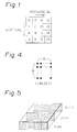
- This variable quantizing of the two-dimensional array of DCT coefficients can be thought of as being carried out by a quantizing unit having different divisors. If a two-dimensional array of DCT coefficients is thought of as being partitioned into 16 areas, these different areas may be depicted as areas 0, 1, ... 15 of FIG. 1.
- the "horizontal" and “vertical” axes represent increasing frequencies in the horizontal and vertical directions, respectively.
- a single quantizing unit exhibits different quantizing steps, or divisors, for the respective areas into which the two-dimensional array is partitioned. Typically, 16 different quantizing units may be provided, with each such unit exhibiting a different quantizing step, or divisor, for each of the 16 areas.
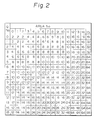
- FIG. 2 is a schematic representation of quantizing units 0, 1, ...15 and further represents the quantizing step, or divisor value for each area shown in FIG. 1, depending upon which quantizing unit is selected. For example, if quantizing unit 2 is selected, the DCT coefficients in areas 0-3 are divided by the divisor 4, the DCT coefficients in areas 4 and 5 are divided by the divisor 6, the DCT coefficients in areas 6-10 are divided by the divisor 8, the DCT coefficient in area 11 is divided by the divisor 10, the DCT coefficients in areas 12, 13 and 14 are divided by the divisor 16 and the DCT coefficient in area 15 is divided by the divisor 32.
- FIG. 2 demonstrates that the higher frequency coefficients are divided by larger divisors, resulting in coarser quantization.
- Quantization with the divisors shown in FIG. 2 have been implemented by multipliers. That is, rather than dividing a DCT coefficient by a divisor, the DCT coefficient is multiplied by a reciprocal of the divisor, that is, by a fraction.
- multipliers are simpler to construct than dividers, the use of a multiplying device generally adds to the complexity and size of the hardware and results in an increase in the cost of the encoding apparatus.
- Relatively simple division of the value of a digital signal can be obtained by use of a shift circuit. It is known that the value of digital data can be divided by 2 simply by shifting that digital signal one place to the right. A division by 4 can be obtained by shifting digital data two places to the right, a division by 8 can be obtained by shifting the digital data three places to the right, and so on.
- simple shift circuits thus can be used to achieve high speed, low cost division, such shift circuits generally are limited to performing division by the factor 2 N . Consequently, quantization by dividing DCT coefficients by a number that is not a power of 2 cannot be performed by such simple shift circuits. That is, quantization by using the different divisors shown in FIG. 2 cannot be attained.
- Another object of this invention is to provide encoding apparatus which quantizes orthogonal transform coefficients with an accuracy that is greater than that achieved by using simple shift circuits and which is less expensive and more efficient to implement than quantization by using multiplier circuits.
- a further object of this invention is to provide compression encoding apparatus which uses orthogonal transformation to produce a two-dimensional array of transform coefficients, the array being partitioned in a direction substantially perpendicular to the oblique frequency axis of the array to form respective areas of coefficients which are quantized with quantizing values that are different for different areas.
- An additional object of this invention is to provide compression encoding apparatus which uses orthogonal transformation to produce a two-dimensional array of transform coefficients, the array being partitioned into respective areas which are quantized by dividing the value of the transform coefficients in different areas by a divisor 2 n/2 where n is an iteger that is different for different areas.
- apparatus for compression encoding video signals.
- a vertical interval such as a field or frame, of video picture elements is segmented into a plurality of blocks of picture elements.
- Each block is orthogonally transformed, such as by discrete cosine transformation (DCT) to a two-dimensional array of transform coefficients for different frequency components.
- the array is partitioned into respective areas; and in one embodiment, the partitioning is in a direction which is substantially perpendicular to the oblique frequency axis of the array.
- Each area is quantized with a respective quantizing value which differs for the different areas.
- each area is quantized by dividing the value of the transform coefficients in that area by a divisor 2 n/2 , where n is an integer which differs for different areas.
- quantizing takes place by dividing the value of a transform coefficient either by a power of 2 or by a multiple power of the root of 2.
- the division of a transform coefficient by the root of 2 is achieved by relatively simple and inexpensive adding circuits and shift circuits.
- the root of 2 is approximated by shifting digital data representing a transform coefficient through a two-place shift circuit, thereby dividing the transform coefficient by 4, shifting the transform coefficient through a three-place shift circuit, thereby dividing the transform coefficient by 8, shifting the transform coefficient through a five-place shift circuit, thereby dividing the transform coefficient by 32, and summing the value of the transform coefficient and the outputs of each of the two-place, three-place and five-place shift circuits so as to provide an approximation of the root of 2.
- the quantized transform coefficients are encoded in variable length code. More particularly, the two-dimensional array of quantized transform coefficients is supplied to a variable length encoder by reading out such coefficients from the array in a zigzag manner from lower frequency coefficients to higher frequency coefficients.
- the variable length encoding is implemented by run length encoding having two data components: one representing the number of successive, quantized transform coefficients of zero value and the other representing the next- following non-zero quantized transform coefficient.
- such variable length encoding is the Huffman code.
- FIG. 3 is a block diagram of video signal compression encoding apparatus in which the present invention finds ready application.
- This apparatus is comprised of a valid information extraction circuit 2, block segmentation circuits 3A-3C, a macro block composition circuit 4, an orthogonal transformation circuit 6, a quantizing circuit 8 and a variable length encoding circuit 9.
- Valid information extraction circuit 2 is coupled to receive digitized luminance and color difference signals and includes an input terminal 1A to receive the digital luminance signal Y and input terminals 1B and 1C to receive the digital color difference signals U and V, respectively.
- the digitized luminance and color difference signals are in the NTSC format.
- other conventional television broadcast standards such as PAL, SECAM or the like may be used.
- the sampling frequency of the luminance signal Y is on the order of about 13.5 MHz and the sampling frequency of each of the color difference signals U and V is on the order of about 6.75 MHz.
- Each digital sample is comprised of 8 bits. It is appreciated, therefore, that valid information extraction circuit 2 is supplied with component signals of the so-called 4:2:2 system.
- the valid information extraction circuit is adapted to remove redundant information from the input luminance and color difference components Y, U and V and thereby extract only that information from which an accurate video picture can be reproduced.
- valid information extraction circuit 2 functions to reduce the amount of information needed to represent a video picture.
- the usual horizontal synchronizing signal, the vertical synchronizing signal and those signals and other information components normally included in the horizontal and vertical blanking intervals are deleted. It is recognized that such signals and information are not needed to reproduce a video picture and, thus, no loss in video accuracy is expected from their deletion.
- the number of samples used to represent the color difference signals U and V may be less than the number of samples that are used to represent the luminance signal Y.
- valid information extraction circuit 2 reduces the number of samples which represent the color difference signals U and V by one-half.
- the luminance samples and color difference samples produced by the valid information extraction circuit are supplied to block segmentation circuits 3A, 3B and 3C, respectively.
- These block segmentation circuits divide a field or frame of luminance picture elements (or pixels) and a field or frame of color difference pixels into individual blocks.
- the expression "vertical interval" is used to refer either to a frame or a field of pixels.
- Each block formed by a block segmentation circuit is referred to, for convenience, as a DCT block because it is this block which is transformed by orthogonal transformation and, as is described below, a preferred form of orthogonal transformation is discrete cosine transformation (DCT).
- DCT discrete cosine transformation
- Each DCT block formed by a block segmentation circuit appears as shown in FIG. 4 and is comprised of an array of 8 x 8 pixels, in which each pixel is represented by 8 bits.
- the DCT block of luminance pixels produced by block segmentation circuit 3A as well as the DCT block of color difference pixels U and the DCT block of color difference pixels V produced by block segmentation circuits 3B and 3C are supplied to macro block composition circuit 4.
- the number of luminance pixels included in a vertical interval is twice the number of color difference pixels U and twice the number of color difference pixels V, and since valid information extraction circuit 2 halves the number of color difference pixels U and V included in the vertical interval, it is appreciated that, in each vertical interval, there are four times the number of luminance pixels than color difference pixels. If it is assumed that one macro block is comprised of four DCT blocks of luminance pixels, then the luminance pixels which constitute these four blocks coincide with one block of color difference pixels U and one block of color difference pixels V. That is, if a set of positions in a video picture is considered, those positions will be occupied by four DCT blocks of luminance pixels, one block of color difference pixels U and one block of color difference pixels V. This is shown more particularly in FIG.
- macro block composition circuit 4 forms a macro block of the four DCT blocks of luminance pixels, the one DCT block of color difference pixels U and the one DCT block of color difference pixels V.
- the formation of a macro block is preferred because this facilitates shuffling and interpolation which, as is known by those of ordinary skill in the art of digital video processing, improves noise immunity.
- the macro blocks formed by macro block composition circuit 4 are coupled to a shuffling circuit 5 which operates in a conventional manner to shuffle the macro blocks. As is known, this minimizes picture degradation in the event of dropout in the recorded digital video data.
- the shuffled macro blocks are supplied to orthogonal transform circuit 6 which operates to derive an orthogonal transformation of each individual block included in the shuffled macro block.
- orthogonal transform circuit 6 which operates to derive an orthogonal transformation of each individual block included in the shuffled macro block.
- discrete cosine transformation derives from an 8 x 8 block of pixel data an array of coefficients, referred to for convenience as DCT coefficients, formed of a DC component and higher frequency components.
- the array of coefficients represents, in the horizontal direction, increasing frequencies and also represents increasing frequencies in the vertical direction. That is, there are higher frequency components in both the horizontal and vertical directions. It is appreciated, therefore, that the array of transform coefficients admits of an oblique frequency axis which increases from the DC component toward higher frequency components.
- the DC component included in the array of transform coefficients is the most important component because it contains the most information representing the video picture.
- the value of the DC component is the largest in the array of transform coefficients. Consequently, when transmitting or recording the encoded digital video signal, the DC component is not further quantized but, rather, is recorded or transmitted substantially as is.
- the DC transform coefficient is supplied directly from DCT circuit 6 to a frame segmenting and error correction encoding circuit 15 which is adapted to form a digital frame of encoded data for recording purposes.
- the higher frequency transform coefficients produced by the DCT circuit are supplied to quantizing circuit 8 for the purpose of data reduction, as by reducing the number of bits used to represent each coefficient, as will be described.
- Quantizing circuit 8 is coupled to variable length encoder 9 to supply quantized transform coefficients thereto.
- the variable length encoder may be of the type which generates a run length code which, as is known to those skilled in the encoding arts, operates to compress the amount of information needed to represent data.
- a suitable run length code is the Huffman code. In this code, the number of successive 0's which separate non-zero data is transmitted as one digital number, or character, and the value of the non-zero data which follows these 0's is transmitted as another character. Thus, and as an example, it each digital sample is comprised of 8 bits, it is not necessary to transmit successive 8-bit samples of zero data.
- Quantizing circuit 8 is adapted to quantize the non-DC transform coefficients produced by DCT circuit 6 by variable amounts. Quantization is obtained by dividing the value of a transform coefficient by a particular divisor.
- the value of the divisor used for the respective transform coefficients in a single array of coefficients varies throughout the array. More particularly, and as is described below, if the array is partitioned into a number of areas, the coefficients in a given area are divided by the same divisor, but the coefficients in a different area are divided by a different divisor.
- the values of these divisors for the different areas are predetermined, and a set of these divisors is associated with a particular quantizing unit. As was the case in the prior art shown in FIG.
- each quantizing unit is composed of a set of different divisors, and a particular divisor is used to quantize the transform coefficients in one or more areas.
- the particular quantizing unit which is chosen to quantize the array of transform coefficients supplied to quantizing circuit 8 is selected by a quantizing unit selection circuit 12 in response to a selecting signal supplied thereto by an estimating circuit 10 which, in turn, estimates the amount of data that will be transmitted by variable length encoding circuit 9 when a particular quantizing unit is selected.
- the array of transform coefficients produced by DCT circuit 6 are stored in a buffer 7 and at the same time supplied to estimating circuit 10.
- the capacity of the buffer is sufficient to store the transform coefficients produced for five macro blocks.
- the estimating circuit is coupled to a Huffman code look- up table 11 and operates to estimate the amount of data that will be included in five macro blocks that are quantized by the selection of a particular quantizing unit and then encoded in Huffman code. If the estimated data is less than a predetermined amount, the preliminary selection of the quantizing unit is changed in a direction which tends to increase the value of the quantized transform coefficients. Then, the amount of data included in the Huffman code which represents the quantized transform coefficients if this newly selected quantizing unit is chosen is estimated once again. Here too, if the amount of data still is less than the aforementioned predetermined amount, the preliminary selection of the quantizing unit is changed once again.
- the quantizing unit which preceded the present selection is chosen to quantize the array of transform coefficients produced by DCT circuit 6.
- This selected quantizing unit is supplied from, for example, a suitable table included in quantizing unit selection circuit 12 to quantizing circuit 8 for quantizing the transform coefficients.
- Quantizing circuit 8 quantizes the transform coefficients of five macro blocks supplied thereto from buffer 7 in accordance with the respective divisors included in the selected quantizing unit.
- the quantized transform coefficients are supplied from the quantizing circuit to variable length encoder 9 which encodes these quantized coefficients in accordance with, for example, Huffman code.
- the resultant Huffman code quantized transform coefficients of five macro blocks are supplied to frame segmenting and error correction encoding circuit 15.
- this circuit composes a digital frame from the DC transform coefficient supplied thereto directly from DCT circuit 6 and from the Huffman code supplied thereto by variable length encoder 9; and adds thereto a suitable error correction code, such as ECC code, parity code, or the like.
- the digital frame formed by circuit 15 is coupled to a channel encoder 16 which modulates the digital data in a form suitable for recording, such as 1,7 code, MFM modulation or other known encoding/modulation schemes.
- the output of the channel encoder is coupled to respective recording heads 18A and 18B by record amplifiers 17A and 17B, respectively.
- the heads function to record the encoded digital video data in respective tracks on a record medium, such as magnetic tape.
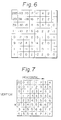
- FIG. 6 is a schematic representation of a typical two-dimensional array of transform coefficients produced by DCT circuit 6 for each DCT block of pixels supplied thereto. It is appreciated that the horizontal and vertical axes in FIG. 6 represent horizontal and vertical frequencies in that portion of the video picture corresponding to the DCT block; and these frequencies increase from the DC coefficient in both the horizontal and vertical directions. Accordingly, the array of FIG. 6 may be thought of as having an oblique frequency axis in the direction from the upper left corner to the lower right corner. It is seen that the transform coefficient of the DC component admits of the largest value (shown in FIG. 6 as "265 "), and as the horizontal and vertical frequencies increase, the values of the corresponding transform coefficients decrease.
- quantizing circuit 8 first partitions the array, excluding the DC transform coefficient, into respective areas.
- the array is partitioned into eight areas shown in FIG. 7 as the areas designated 0, 1, 2, ...6, 7. It is appreciated that these successive areas are formed in a direction substantially perpendicular to the oblique frequency axis of the two-dimensional array. If a given quantizing unit is selected, all of the transform coefficients included in a particular area are quantized by the same quantizing step, and the value of this quantizing step is different in the different areas.
- Quantization is obtained by dividing the value of a transform coefficient by a divisor; and the values of the different divisors used to divide the transform coefficients in the different areas are illustrated in FIG. 8.
- quantizing unit 0 quantizing unit 1
- quantizing unit 2 quantizing unit 2
- ...quantizing unit 15 each quantizing unit provides distinctive divisors for the respective areas in which the two-dimensional array is partitioned.
- the transform coefficients are quantized by dividing their values by the root of 2 (i.e. 2 1/2 ), which is represented in FIG. 8 as "SQ".
- the transform coefficients disposed in area 4 are quantized by dividing their values by 2;
- the transform coefficients in area 5 are quantized by dividing their values by two times the root of 2 (i.e. 2 3/2 , which is represented as 2SQ);
- the transform coefficients disposed in area 6 are quantized by dividing their values by 4;
- the transform coefficients disposed in area 7 are quantized by dividing their values by four times the root of 2 (i.e. 2 5/2 , represented as 4SQ).
- quantizing unit 2 is selected to quantize the transform coefficients included in the two-dimensional array of FIG. 6, those transform coefficients which are disposed in area zero are quantized by dividing their values by 2, the transform coefficients disposed in areas 1 and 2 are quantized by dividing their values by 2 3/2 (or 2SQ), the transform coefficients disposed in area 3 are quantized by dividing their values by 4, the transform coefficients disposed in areas 4, 5 and 6 are quantized by dividing their values by 2 5/2 (or 4SQ), and the transform coefficients disposed in area 7 are quantized by dividing their values by 8. Any remainder obtained by such division is rounded off, as is conventional. It will be appreciated, then, that most of the quantized transform coefficients are reduced to an effective value of 0.
- the two-dimensional array of quantized transform coefficients is supplied from quantizing circuit 8 to variable length encoder 9 by scanning the two-dimensional array in a zigzag manner, such as depicted in FIG. 9. Thus, respective areas are scanned in the direction from transform coefficients representing lower frequencies to transform coefficients representing higher frequencies. It is appreciated from the foregoing discussion that, since much of the quantized data is reduced to 0, the transform coefficients which are supplied to encoder 9 as a result of the zigzag scanning of the two-dimensional array supplies a significant amount of redundant, unnecessary data. This data is further compressed by variable length encoder 9 which, for example, compresses the quantized transform coefficients by using the Huffman code.
- variable length code two data characters are transmitted: one to represent the number of successive quantized transform coefficients of less than a threshold value, which are rounded off to zero, and which precede a quantized transform coefficient which exceeds that threshold value and a second data character to represent the magnitude of that non-zero quantized transform coefficient.
- FIG. 10 An example of a variable length code representing quantized transform coefficients is schematically illustrated in FIG. 10, wherein it is assumed that a non-zero transmission coefficient having an arbitrary value of 5 is separated by two zero-value transform coefficients from the next non-zero transform coefficient, the latter having an arbitrary value of 2.
- each transform coefficient is represented by an 8-bit data character, thirteen data characters would be needed to represent the transform coefficients depicted in FIG. 10. However, by using Huffman code, or other suitable variable length code, only eight data characters are needed, as follows: (0, 5), (2, 2), (5, 1), (2, 1).
- a represents the number of zero-value transmission coefficients which precede the non-zero transmission coefficient b
- b represents the value of that non-zero transmission coefficient.
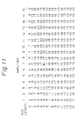
- An example of a Huffman table which may be used as the variable length code is illustrated in FIG. 11, wherein the column "run length” represents the number of successive 0's that precede non-zero data and the row "amplitude" represents the value of the non-zero data.
- quantization of a transform coefficient is obtained by dividing the value of that transform coefficient by a divisor that is either a power of 2 (e.g. 2 N ) or a power of 2 times the root of 2 (e.g. 2 N x 2 1/2 ). Stated more generally, if N is an even number, then the divisor has a value 2 n ; and if N is an odd number, the divisor has a value 2 n/2 . In general, then, the divisor may be expressed as the value 2 n/2 , where n is an integer (both odd and even).
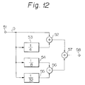
- FIG. 12 is a block diagram representing one embodiment of an approximation circuit which serves to multiply the value D of a transform coefficient (or of any other digital signal) by approximately the root of 2.
- the value 2 1/2 is approximated by 1 + 1/4 + 1/8 + 1/32.
- Shift circuit 53 is a divide by 4 circuit that may be constructed as a shift circuit which shifts the digital signal D two places to the right.
- Shift circuit 54 is a divide by 8 circuit and may be constructed as a shift circuit which shifts the digital signal D three places to the right.
- shift circuit 55 is a divide by 32 circuit and may be constructed as a shift circuit which shifts the digital signal D five places to the right.
- a summing circuit serves to sum the digital signal D supplied to input terminal 51 as well as the outputs of shift circuits 53, 54 and 55, resulting in an output signal whose value is D(1 + 1/4 + 1/8 + 1/32), which is a reasonably good approximation of D x 2 1/2 .
- individual summing circuits 52, 56 and 57 are used, wherein summing circuit 52 sums D + D/4, summing circuit 56 sums D/8 + D/32 and summing circuit 57 sums the outputs of summing circuits 52 and 56, or D(1 + 1/4 + 1/8 + 1/32).
- output terminal 58 which is coupled to summing circuit 57, provides a digital signal that is a close approximation of D 2
- n-place shift circuit when a transform coefficient is divided by the divisor 2 n , a simple n-place shift circuit may be used. However, when the transform coefficient is quantized by dividing its value by 2 n/2 , the digital signal representing the transform coefficient is shifted by a (n-1) place shift circuit as well as the circuit illustrated in FIG. 12. If such shift circuits are connected in cascade, terminal 58 in FIG. 12 provides a quantized transform coefficient whose value is divided by the divisor 2 n/2 .
Claims (11)
- Vorrichtung zur Kompressionscodierung von Videosignalen, aufweisend: eine Blocksegmentierungseinrichtung (3A, 3B, 3C) zur Segmentierung eines vertikalen Bereichs von Videobildelementen in mehrere Blöcke von Bildelementen, eine Orthogonal-Transformationseinrichtung (6) zur Orthogonaltransformation von jeweiligen Blöcken, wobei die Orthogonaltransformation eines Blocks durch eine zweidimensionale Anordnung an Transformationskoeffizienten verschiedener Werte wiedergegeben wird, eine Einrichtung zur Einteilung der zweidimensionalen Matrix an Transformationskoeffizienten in jeweilige Bereiche, und eine Quantisierungseinrichtung zur Quantisierung der Bereiche mit jeweiligen Quantisierungswerten, dadurch gekennzeichnet, daßdie Quantisierungseinrichtung dazu vorgesehen ist, den Wert der Transformationskoeffizienten in den Bereichen durch einen jeweiligen Divisor 2n/2 zu teilen, wobei n eine ganze Zahl ist, die für verschiedene Bereiche unterschiedlich ist, unddaß die Quantisieiungseinrichtung mehrere Verschiebungsschaltungen (53, 54, 55) aufweist, deren Eingänge zur Aufnahme von Transformationskoeffizientendaten miteinander verbunden sind, und eine Einrichtung (52, 56, 57) zur Addition verschobener Daten, die durch die Verschiebeschaltungen erzeugt wurden, um eine Näherung des Teilers 21/2 zu schaffen.
- Vorrichtung nach Anspruch 1,
bei der die Schiebeschaltungen (53, 54, 55) eine Zweiplatz-Verschiebeschaltung (53) zur Teilung der Transformationskoeffizientendaten D um 4 (D/4), eine Dreiplatz-Verschiebeschaltung (54) zur Teilung der Transformationskoeffizientendaten um 8 (D/8) und eine Fünfplatz-Verschiebeschaltung (55) zur Teilung der Transformationskoeffizientendaten um 32 (D/32) aufweist, und bei der die Einrichtung (52, 56, 57) zur Addition der Verschiebedaten einen Wert der Transformationsdaten D (1 + 1/4 + 1/8 + 1/32) erhält. - Vorrichtung nach einem der Ansprüche 1 oder 2,
bei der die Orthogonal-Transformationseinrichtung (6) eine Einrichtung zur Erhaltung einer diskreten Cosinustransformation jeweiliger Blöcke an Bildelementen aufweist. - Vorrichtung nach einem der Ansprüche 1 bis 3,
weiterhin aufweisend eine Einrichtung (9) zur Codierung mit variabler Länge, die mit der Quantisierungseinrichtung (8) verbunden ist, um die quantisierten Transformationskoeffizienten mit einem Code mit variabler Länge zu codieren. - Vorrichtung nach Anspruch 4,
wobei der Code mit variabler Länge ein Lauflängencode ist. - Vorrichtung nach Anspruch 4,
bei dem der Code mit variabler Länge ein Huffman-Code ist. - Vorrichtung nach einem der Ansprüche 4 bis 6,
bei der die Transformationskoeffizienten in der zweidimensionalen Matrix Komponenten höherer Frequenz sowohl in der horizontalen wie auch in der vertikalen Richtung wiedergeben, und weiterhin eine Einrichtung zum Abtasten der zweidimensionalen Matrix in einer Zickzack-Weise von den Komponenten niedriger Frequenz in Richtung der Komponenten höherer Frequenz vorgesehen ist, um die quantisierten Transformationsdaten zu der Codierungseinrichtung mit variabler Länge zu geben. - Vorrichtung nach Anspruch 7,
bei der die Codierungseinrichtung mit variabler Länge eine Einrichtung zur Erzeugung eines ersten Datensignals, das die Anzahl an sukzessiv abgetasteten quantisierten Transformationskoeffizienten wiedergibt, die kleiner als ein Schwellenwert sind, und ein zweites Datensignal aufweist, das den Wert des unmittelbar folgenden Transformationskoeffizienten wiedergibt, der den Schwellenwert überschreitet. - Vorrichtung nach Anspruch 7 oder 8,
bei der die zweidimensionale Matrix eine schräge Frequenzachse aufweist, wobei die jeweiligen Bereiche, in die die zweidimensionale Matrix unterteilt ist, im wesentlichen senkrecht zu der schrägen Achse sind, und die Einrichtung zur Abtastung der zweidimensionalen Matrix die Transformationskoeffizienten in den entsprechenden Bereichen von niedrigen zu höheren Frequenzen zu der Einrichtung zur Codierung mit variabler Länge gibt. - Vorrichtung nach Anspruch 4,
bei der die quantisierten Transformationskoeffizienten zu der Codierungseinrichtung mit variabler Länge von dem jeweiligen Bereich von den Komponenten niedrigerer Frequenz in Richtung Komponenten höherer Frequenz gegeben werden. - Vorrichtung nach einem der vorhergehenden Ansprüche,
bei der die Orthogonal-Transformationseinrichtung (6) eine diskrete Cosinus-Transformationseinrichtung aufweist.
Applications Claiming Priority (2)
| Application Number | Priority Date | Filing Date | Title |
|---|---|---|---|
| JP35863191A JP3298915B2 (ja) | 1991-12-28 | 1991-12-28 | 符号化装置 |
| JP358631/91 | 1991-12-28 |
Publications (3)
| Publication Number | Publication Date |
|---|---|
| EP0550012A2 EP0550012A2 (de) | 1993-07-07 |
| EP0550012A3 EP0550012A3 (de) | 1994-04-20 |
| EP0550012B1 true EP0550012B1 (de) | 1998-07-08 |
Family
ID=18460315
Family Applications (1)
| Application Number | Title | Priority Date | Filing Date |
|---|---|---|---|
| EP19920121906 Expired - Lifetime EP0550012B1 (de) | 1991-12-28 | 1992-12-23 | Vorrichtung zur Kompressionskodierung von Videosignalen |
Country Status (7)
| Country | Link |
|---|---|
| US (1) | US5347310A (de) |
| EP (1) | EP0550012B1 (de) |
| JP (1) | JP3298915B2 (de) |
| KR (1) | KR100254505B1 (de) |
| AU (1) | AU653877B2 (de) |
| CA (1) | CA2086316C (de) |
| DE (1) | DE69226160T2 (de) |
Families Citing this family (28)
| Publication number | Priority date | Publication date | Assignee | Title |
|---|---|---|---|---|
| US5355450A (en) | 1992-04-10 | 1994-10-11 | Avid Technology, Inc. | Media composer with adjustable source material compression |
| JP2518503B2 (ja) * | 1993-03-08 | 1996-07-24 | 日本電気株式会社 | 画面切り替え検出方法 |
| US6674897B1 (en) * | 1993-09-08 | 2004-01-06 | Sony Corporation | Picture data compression device and red data detection device |
| JP3202433B2 (ja) * | 1993-09-17 | 2001-08-27 | 株式会社リコー | 量子化装置、逆量子化装置及び画像処理装置並びに量子化方法、逆量子化方法及び画像処理方法 |
| US5617333A (en) * | 1993-11-29 | 1997-04-01 | Kokusai Electric Co., Ltd. | Method and apparatus for transmission of image data |
| KR0129573B1 (ko) * | 1994-04-30 | 1998-04-10 | 배순훈 | 디지탈 화상 복호화를 위한 디씨(dc) 계수의 오차보상 방법 |
| JP3336754B2 (ja) * | 1994-08-19 | 2002-10-21 | ソニー株式会社 | デジタルビデオ信号の記録方法及び記録装置 |
| US5644504A (en) * | 1995-03-27 | 1997-07-01 | International Business Machines Corporation | Dynamically partitionable digital video encoder processor |
| US6026232A (en) * | 1995-07-13 | 2000-02-15 | Kabushiki Kaisha Toshiba | Method and system to replace sections of an encoded video bitstream |
| US5819004A (en) * | 1995-05-08 | 1998-10-06 | Kabushiki Kaisha Toshiba | Method and system for a user to manually alter the quality of previously encoded video frames |
| US5684714A (en) * | 1995-05-08 | 1997-11-04 | Kabushiki Kaisha Toshiba | Method and system for a user to manually alter the quality of a previously encoded video sequence |
| US6574416B1 (en) * | 1995-11-02 | 2003-06-03 | Videa, Llc | Picture-based video indexing system |
| JPH10117350A (ja) * | 1996-10-09 | 1998-05-06 | Matsushita Electric Ind Co Ltd | アナログ処理方式の画像符号化装置 |
| US6037985A (en) * | 1996-10-31 | 2000-03-14 | Texas Instruments Incorporated | Video compression |
| US6339614B1 (en) * | 1996-12-20 | 2002-01-15 | Intel Corporation | Method and apparatus for quantizing and run length encoding transform coefficients in a video coder |
| US6594398B1 (en) * | 1998-03-06 | 2003-07-15 | Divio, Inc. | Method and apparatus for run-length encoding video data |
| US7221761B1 (en) * | 2000-09-18 | 2007-05-22 | Sharp Laboratories Of America, Inc. | Error resilient digital video scrambling |
| US7130876B2 (en) * | 2001-11-30 | 2006-10-31 | General Instrument Corporation | Systems and methods for efficient quantization |
| AU2003304049A1 (en) * | 2003-03-28 | 2004-11-19 | Ess Technology, Inc. | Variable rate sigma delta modulator |
| US7564874B2 (en) | 2004-09-17 | 2009-07-21 | Uni-Pixel Displays, Inc. | Enhanced bandwidth data encoding method |
| EP1890475A1 (de) * | 2006-08-15 | 2008-02-20 | STMicroelectronics (Research & Development) Limited | Videobildspeicher |
| US8345162B2 (en) * | 2007-07-31 | 2013-01-01 | Verint Systems Inc. | Systems and methods for triggering an out of focus alert |
| US20110090952A1 (en) * | 2009-10-21 | 2011-04-21 | Cohen Robert A | Directional Transforms for Video and Image Coding |
| KR101650381B1 (ko) * | 2010-02-02 | 2016-08-23 | 엘지전자 주식회사 | 입체 영상 보정 장치 및 방법 |
| US8780972B2 (en) | 2011-02-25 | 2014-07-15 | Blackberry Limited | Methods and devices for data compression using offset-based adaptive reconstruction levels |
| US20130083845A1 (en) | 2011-09-30 | 2013-04-04 | Research In Motion Limited | Methods and devices for data compression using a non-uniform reconstruction space |
| EP2575364B1 (de) | 2011-09-30 | 2020-03-18 | BlackBerry Limited | Verfahren und Vorrichtungen zur Datenkomprimierung mithilfe eines ungleichförmigen Rekonstruktionsraums |
| EP2595382B1 (de) | 2011-11-21 | 2019-01-09 | BlackBerry Limited | Verfahren und Vorrichtungen zur Codierung und Decodierung von Transformationsdomänenfiltern |
Family Cites Families (10)
| Publication number | Priority date | Publication date | Assignee | Title |
|---|---|---|---|---|
| ATE25177T1 (de) * | 1982-10-14 | 1987-02-15 | British Telecomm | Bilduebertragung. |
| US4698672A (en) * | 1986-10-27 | 1987-10-06 | Compression Labs, Inc. | Coding system for reducing redundancy |
| BE1000643A5 (fr) * | 1987-06-05 | 1989-02-28 | Belge Etat | Procede de codage de signaux d'image. |
| US4972260A (en) * | 1988-08-22 | 1990-11-20 | Matsushita Electric Industrial Co., Ltd. | Apparatus for coding a moving-picture signal |
| EP0366435B1 (de) * | 1988-10-27 | 1998-12-23 | Matsushita Electric Industrial Co., Ltd. | Gerät für die direkte oder umgekehrte orthogonale Transformation |
| JPH0797753B2 (ja) * | 1989-01-24 | 1995-10-18 | 日本ビクター株式会社 | 符号化出力データ量の制御方式 |
| US5073821A (en) * | 1989-01-30 | 1991-12-17 | Matsushita Electric Industrial Co., Ltd. | Orthogonal transform coding apparatus for reducing the amount of coded signals to be processed and transmitted |
| JPH02226886A (ja) * | 1989-02-28 | 1990-09-10 | Sony Corp | データ伝送装置及び伝送方法 |
| FR2660139B1 (fr) * | 1990-03-23 | 1995-08-25 | France Etat | Procede de codage et de transmission a au moins deux niveaux de qualite d'images numeriques appartenant a une sequence d'images, et dispositifs correspondants. |
| US5150208A (en) * | 1990-10-19 | 1992-09-22 | Matsushita Electric Industrial Co., Ltd. | Encoding apparatus |
-
1991
- 1991-12-28 JP JP35863191A patent/JP3298915B2/ja not_active Expired - Lifetime
-
1992
- 1992-12-16 US US07/991,267 patent/US5347310A/en not_active Expired - Lifetime
- 1992-12-17 KR KR1019920024559A patent/KR100254505B1/ko not_active IP Right Cessation
- 1992-12-23 DE DE1992626160 patent/DE69226160T2/de not_active Expired - Fee Related
- 1992-12-23 EP EP19920121906 patent/EP0550012B1/de not_active Expired - Lifetime
- 1992-12-24 CA CA 2086316 patent/CA2086316C/en not_active Expired - Lifetime
- 1992-12-24 AU AU30442/92A patent/AU653877B2/en not_active Expired
Also Published As
| Publication number | Publication date |
|---|---|
| KR100254505B1 (ko) | 2000-05-01 |
| EP0550012A2 (de) | 1993-07-07 |
| CA2086316A1 (en) | 1993-06-29 |
| AU3044292A (en) | 1993-07-01 |
| KR930015821A (ko) | 1993-07-24 |
| CA2086316C (en) | 2003-05-13 |
| US5347310A (en) | 1994-09-13 |
| DE69226160D1 (de) | 1998-08-13 |
| AU653877B2 (en) | 1994-10-13 |
| DE69226160T2 (de) | 1998-11-12 |
| JPH05183890A (ja) | 1993-07-23 |
| EP0550012A3 (de) | 1994-04-20 |
| JP3298915B2 (ja) | 2002-07-08 |
Similar Documents
| Publication | Publication Date | Title |
|---|---|---|
| EP0550012B1 (de) | Vorrichtung zur Kompressionskodierung von Videosignalen | |
| EP0619059B1 (de) | Verfahren und vorrichtung zur bilddatenkompression durch luminanz/chrominanz-kodierung | |
| EP0558016B1 (de) | Verfahren und Vorrichtung zur Bildsignalkodierung mit merhstufigen Quantisierungnummernbestimmung | |
| US5301018A (en) | Method and apparatus for shuffling image data into statistically averaged data groups and for deshuffling the data | |
| US5170264A (en) | Compression coding device and expansion decoding device for a picture signal | |
| JP3134424B2 (ja) | 可変長符号化方法及び装置 | |
| US5374958A (en) | Image compression based on pattern fineness and edge presence | |
| US5321440A (en) | High efficiency data compressed image encoding | |
| EP0663778B1 (de) | Bildkodierungsverfahren und -vorrichtung | |
| KR960015510B1 (ko) | 기록재생장치 | |
| US5572331A (en) | Video signal recording format, deep recording/reproducing apparatus and method therefor | |
| JPH04373286A (ja) | 画像符号化装置 | |
| US5745644A (en) | Method and apparatus for encoding a digital video signal | |
| JP3271098B2 (ja) | ディジタル画像信号復号装置および方法 | |
| EP0523708A2 (de) | Verfahren und Vorrichtung zum Aufzeichnen von digitalen Videosignalen | |
| JP3125471B2 (ja) | ディジタルビデオ信号記録装置におけるフレーム化装置 | |
| JPH05176311A (ja) | 画像符号化装置 | |
| JPH06292020A (ja) | 画像符号復号方法ならびに装置 | |
| JPH05316496A (ja) | 符号化装置 | |
| JPH05130424A (ja) | 画像符号化装置 | |
| JPH0514739A (ja) | 画像符号化装置 | |
| JPH0530536A (ja) | 画像符号化装置 | |
| JPH0514875A (ja) | 画像符号化装置 | |
| JPH06233240A (ja) | 磁気記録再生装置 | |
| JPH06217279A (ja) | 画像データ処理装置 |
Legal Events
| Date | Code | Title | Description |
|---|---|---|---|
| PUAI | Public reference made under article 153(3) epc to a published international application that has entered the european phase |
Free format text: ORIGINAL CODE: 0009012 |
|
| AK | Designated contracting states |
Kind code of ref document: A2 Designated state(s): DE FR GB NL |
|
| PUAL | Search report despatched |
Free format text: ORIGINAL CODE: 0009013 |
|
| RHK1 | Main classification (correction) |
Ipc: H04N 7/133 |
|
| AK | Designated contracting states |
Kind code of ref document: A3 Designated state(s): DE FR GB NL |
|
| 17P | Request for examination filed |
Effective date: 19940926 |
|
| 17Q | First examination report despatched |
Effective date: 19961106 |
|
| GRAG | Despatch of communication of intention to grant |
Free format text: ORIGINAL CODE: EPIDOS AGRA |
|
| GRAG | Despatch of communication of intention to grant |
Free format text: ORIGINAL CODE: EPIDOS AGRA |
|
| GRAH | Despatch of communication of intention to grant a patent |
Free format text: ORIGINAL CODE: EPIDOS IGRA |
|
| GRAH | Despatch of communication of intention to grant a patent |
Free format text: ORIGINAL CODE: EPIDOS IGRA |
|
| GRAA | (expected) grant |
Free format text: ORIGINAL CODE: 0009210 |
|
| AK | Designated contracting states |
Kind code of ref document: B1 Designated state(s): DE FR GB NL |
|
| REF | Corresponds to: |
Ref document number: 69226160 Country of ref document: DE Date of ref document: 19980813 |
|
| ET | Fr: translation filed | ||
| PLBE | No opposition filed within time limit |
Free format text: ORIGINAL CODE: 0009261 |
|
| STAA | Information on the status of an ep patent application or granted ep patent |
Free format text: STATUS: NO OPPOSITION FILED WITHIN TIME LIMIT |
|
| 26N | No opposition filed | ||
| PGFP | Annual fee paid to national office [announced via postgrant information from national office to epo] |
Ref country code: FR Payment date: 20011212 Year of fee payment: 10 |
|
| PGFP | Annual fee paid to national office [announced via postgrant information from national office to epo] |
Ref country code: GB Payment date: 20011227 Year of fee payment: 10 |
|
| PGFP | Annual fee paid to national office [announced via postgrant information from national office to epo] |
Ref country code: NL Payment date: 20011228 Year of fee payment: 10 |
|
| REG | Reference to a national code |
Ref country code: GB Ref legal event code: IF02 |
|
| PGFP | Annual fee paid to national office [announced via postgrant information from national office to epo] |
Ref country code: DE Payment date: 20020109 Year of fee payment: 10 |
|
| PG25 | Lapsed in a contracting state [announced via postgrant information from national office to epo] |
Ref country code: GB Free format text: LAPSE BECAUSE OF NON-PAYMENT OF DUE FEES Effective date: 20021223 |
|
| PG25 | Lapsed in a contracting state [announced via postgrant information from national office to epo] |
Ref country code: NL Free format text: LAPSE BECAUSE OF NON-PAYMENT OF DUE FEES Effective date: 20030701 Ref country code: DE Free format text: LAPSE BECAUSE OF NON-PAYMENT OF DUE FEES Effective date: 20030701 |
|
| GBPC | Gb: european patent ceased through non-payment of renewal fee |
Effective date: 20021223 |
|
| NLV4 | Nl: lapsed or anulled due to non-payment of the annual fee |
Effective date: 20030701 |
|
| PG25 | Lapsed in a contracting state [announced via postgrant information from national office to epo] |
Ref country code: FR Free format text: LAPSE BECAUSE OF NON-PAYMENT OF DUE FEES Effective date: 20030901 |
|
| REG | Reference to a national code |
Ref country code: FR Ref legal event code: ST |