EP0543383B1 - Verfahren zur Bearbeitung von Steuerkanten auf den Kolben der Kraftstoffeinspritzpumpen - Google Patents
Verfahren zur Bearbeitung von Steuerkanten auf den Kolben der Kraftstoffeinspritzpumpen Download PDFInfo
- Publication number
- EP0543383B1 EP0543383B1 EP92119747A EP92119747A EP0543383B1 EP 0543383 B1 EP0543383 B1 EP 0543383B1 EP 92119747 A EP92119747 A EP 92119747A EP 92119747 A EP92119747 A EP 92119747A EP 0543383 B1 EP0543383 B1 EP 0543383B1
- Authority
- EP
- European Patent Office
- Prior art keywords
- machining
- plunger
- hole
- lead
- port hole
- Prior art date
- Legal status (The legal status is an assumption and is not a legal conclusion. Google has not performed a legal analysis and makes no representation as to the accuracy of the status listed.)
- Expired - Lifetime
Links
- 238000003754 machining Methods 0.000 title claims description 43
- 238000002347 injection Methods 0.000 title claims description 34
- 239000007924 injection Substances 0.000 title claims description 34
- 239000000446 fuel Substances 0.000 title claims description 33
- 238000000034 method Methods 0.000 claims description 21
- 238000005520 cutting process Methods 0.000 claims description 8
- 239000006185 dispersion Substances 0.000 description 8
- 238000010586 diagram Methods 0.000 description 4
- 238000005086 pumping Methods 0.000 description 4
- 238000005259 measurement Methods 0.000 description 3
- 238000004891 communication Methods 0.000 description 2
- 230000009467 reduction Effects 0.000 description 2
- 229910000831 Steel Inorganic materials 0.000 description 1
- 230000002411 adverse Effects 0.000 description 1
- 229910052799 carbon Inorganic materials 0.000 description 1
- 229910052804 chromium Inorganic materials 0.000 description 1
- 239000011651 chromium Substances 0.000 description 1
- 230000006835 compression Effects 0.000 description 1
- 238000007906 compression Methods 0.000 description 1
- 230000003631 expected effect Effects 0.000 description 1
- 230000001788 irregular Effects 0.000 description 1
- 238000004519 manufacturing process Methods 0.000 description 1
- 239000002994 raw material Substances 0.000 description 1
- 230000001105 regulatory effect Effects 0.000 description 1
- 239000010959 steel Substances 0.000 description 1
- 239000004575 stone Substances 0.000 description 1
Images


Classifications
-
- F—MECHANICAL ENGINEERING; LIGHTING; HEATING; WEAPONS; BLASTING
- F02—COMBUSTION ENGINES; HOT-GAS OR COMBUSTION-PRODUCT ENGINE PLANTS
- F02M—SUPPLYING COMBUSTION ENGINES IN GENERAL WITH COMBUSTIBLE MIXTURES OR CONSTITUENTS THEREOF
- F02M59/00—Pumps specially adapted for fuel-injection and not provided for in groups F02M39/00 -F02M57/00, e.g. rotary cylinder-block type of pumps
- F02M59/20—Varying fuel delivery in quantity or timing
- F02M59/24—Varying fuel delivery in quantity or timing with constant-length-stroke pistons having variable effective portion of stroke
- F02M59/26—Varying fuel delivery in quantity or timing with constant-length-stroke pistons having variable effective portion of stroke caused by movements of pistons relative to their cylinders
- F02M59/265—Varying fuel delivery in quantity or timing with constant-length-stroke pistons having variable effective portion of stroke caused by movements of pistons relative to their cylinders characterised by the arrangement or form of spill port of spill contour on the piston
-
- F—MECHANICAL ENGINEERING; LIGHTING; HEATING; WEAPONS; BLASTING
- F02—COMBUSTION ENGINES; HOT-GAS OR COMBUSTION-PRODUCT ENGINE PLANTS
- F02M—SUPPLYING COMBUSTION ENGINES IN GENERAL WITH COMBUSTIBLE MIXTURES OR CONSTITUENTS THEREOF
- F02M59/00—Pumps specially adapted for fuel-injection and not provided for in groups F02M39/00 -F02M57/00, e.g. rotary cylinder-block type of pumps
- F02M59/44—Details, components parts, or accessories not provided for in, or of interest apart from, the apparatus of groups F02M59/02 - F02M59/42; Pumps having transducers, e.g. to measure displacement of pump rack or piston
-
- F—MECHANICAL ENGINEERING; LIGHTING; HEATING; WEAPONS; BLASTING
- F02—COMBUSTION ENGINES; HOT-GAS OR COMBUSTION-PRODUCT ENGINE PLANTS
- F02M—SUPPLYING COMBUSTION ENGINES IN GENERAL WITH COMBUSTIBLE MIXTURES OR CONSTITUENTS THEREOF
- F02M59/00—Pumps specially adapted for fuel-injection and not provided for in groups F02M39/00 -F02M57/00, e.g. rotary cylinder-block type of pumps
- F02M59/20—Varying fuel delivery in quantity or timing
- F02M59/24—Varying fuel delivery in quantity or timing with constant-length-stroke pistons having variable effective portion of stroke
-
- Y—GENERAL TAGGING OF NEW TECHNOLOGICAL DEVELOPMENTS; GENERAL TAGGING OF CROSS-SECTIONAL TECHNOLOGIES SPANNING OVER SEVERAL SECTIONS OF THE IPC; TECHNICAL SUBJECTS COVERED BY FORMER USPC CROSS-REFERENCE ART COLLECTIONS [XRACs] AND DIGESTS
- Y10—TECHNICAL SUBJECTS COVERED BY FORMER USPC
- Y10T—TECHNICAL SUBJECTS COVERED BY FORMER US CLASSIFICATION
- Y10T29/00—Metal working
- Y10T29/49—Method of mechanical manufacture
- Y10T29/49229—Prime mover or fluid pump making
- Y10T29/49236—Fluid pump or compressor making
-
- Y—GENERAL TAGGING OF NEW TECHNOLOGICAL DEVELOPMENTS; GENERAL TAGGING OF CROSS-SECTIONAL TECHNOLOGIES SPANNING OVER SEVERAL SECTIONS OF THE IPC; TECHNICAL SUBJECTS COVERED BY FORMER USPC CROSS-REFERENCE ART COLLECTIONS [XRACs] AND DIGESTS
- Y10—TECHNICAL SUBJECTS COVERED BY FORMER USPC
- Y10T—TECHNICAL SUBJECTS COVERED BY FORMER US CLASSIFICATION
- Y10T29/00—Metal working
- Y10T29/49—Method of mechanical manufacture
- Y10T29/49229—Prime mover or fluid pump making
- Y10T29/49249—Piston making
-
- Y—GENERAL TAGGING OF NEW TECHNOLOGICAL DEVELOPMENTS; GENERAL TAGGING OF CROSS-SECTIONAL TECHNOLOGIES SPANNING OVER SEVERAL SECTIONS OF THE IPC; TECHNICAL SUBJECTS COVERED BY FORMER USPC CROSS-REFERENCE ART COLLECTIONS [XRACs] AND DIGESTS
- Y10—TECHNICAL SUBJECTS COVERED BY FORMER USPC
- Y10T—TECHNICAL SUBJECTS COVERED BY FORMER US CLASSIFICATION
- Y10T29/00—Metal working
- Y10T29/49—Method of mechanical manufacture
- Y10T29/49405—Valve or choke making
- Y10T29/49412—Valve or choke making with assembly, disassembly or composite article making
- Y10T29/49416—Valve or choke making with assembly, disassembly or composite article making with material shaping or cutting
- Y10T29/49419—Valve or choke making with assembly, disassembly or composite article making with material shaping or cutting including machining or drilling
Definitions
- the present invention relates to a process for machining a lead of a plunger to he used in a fuel injection pump especially of the type having a variable fuel injection rate.
- a variable fuel injection rate type is known as one of the types of an in-line type fuel injection pump in a diesel engine.
- the fuel injection pump of this type has its plunger prestroke adjusted by changing the axial position of a control sleeve with respect to the plunger.
- This fuel injection pump is disclosed in JP-A-61-123756 (corresponding to GB-A-2169357), JP-A-61-218769 (corresponding to EP-A-181402), JP-A-1-117981 and JP-Y-61-35727.
- a plunger on which is fitted relatively movably a control sleeve.
- the plunger has its upper end facing an upper fuel compression chamber and formed at its center with an axial bore which extends in the axial direction.
- the plunger is formed in its outer circumference with a longitudinal groove and a lead (i.e., inclined groove) intersecting with the former groove.
- This longitudinal groove has communication with the axial bore via a radial bore.
- the control sleeve is formed with a radial spill port.
- This prestroke can be changed by displacing the control sleeve in the axial direction of the plunger by the control rod.
- a time period after the prestroke and before communication between the lead and the spill port is the pumping effective stroke, for which the fuel is pumped.
- the pumping effective stroke can also be changed by turning the plunger relative to the control sleeve.
- the lead and the spill port are aligned in the circumferential direction, there is established a non-injection state, in which the fuel is not compressed in the least by the plunger.
- variable injection rate type fuel injection pump tends to be widely used.
- the position and size of the lead of the plunger have to be highly accurate. This high accuracy is difficult to achieve in the prior art.
- the ordinary in-line type fuel injection pump finds it relatively easy to reduce the dispersion of the fuel-pumping effective stroke because what the barrel undergoes is the vertical reciprocations of the plunger.
- the control sleeve is moved up and down relative to the plunger.
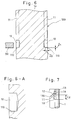
- both the length from the lower end of the control sleeve to the edge of the spill port and the length L2 from the lower end of a port hole 10 of a plunger 10, as shown in Fig. 7, to the branching starting portion of the lead are effective to cause the dispersion of the fuel-pumping effective stroke.
- a longitudinal groove 11 and a leads 12 have to be formed not at the upper end of the plunger 1 but at predetermined lower distances than the upper end.
- the lead has found it so seriously difficult to machine in the normal position that its positioning accuracy has failed to improve.
- the plunger has a basic structure shown in Fig. 8-A by way of example.
- a plunger body 1a having a predetermined external diameter and across a neck portion 1b
- a face portion 1c below which is formed a bottom end 1e across a neck portion 1d.
- the bottom end 1e is in abutment against the not-shown cam through a tappet so that the plunger reciprocates along the contour of the cam.
- the face portion 1c is so engaged by an injection rate adjusting sleeve other than the aforementioned control sleeve that its turning motion is regulated by the adjusting sleeve.
- a plunger blank 100 which has been worked to the state shown in Fig. 8-A (i.e., to the state at which it has not been hardened yet), is machined on the basis of information inputted in advance to an NC machine, to form both an axial bore 13 having a desired depth from the upper end face and a round port hole 10 in a predetermined circumferential position.
- the plunger blank 100 is hardened to have its hardness increased.
- the length L3 from the lower end of the port hole 10 to the bottom face 1f of the bottom end 1e is measured, as shown in Fig. 8-B, and is classified according to the difference from a reference size. This is because the hole position will disperse due to not only a machining error before the hardening step but also a deformation at the hardening step.
- the plunger blank 100 is chucked by the machine tool, and the programmed numerical value or coordinate of the length L3 inputted in advance to a NC machine 2 is corrected according to the aforementioned classification, as shown in Fig. 8-C.
- the machine body and its machining head 3 are moved relative to each other with reference to the machining reference plane of the bottom face 1f of the plunger bottom end in accordance with a control command having correcting program data, thereby to machine the longitudinal groove 11 and the lead 12.
- the machining reference is located at the plunger lower end (or its bottom face).
- the length L2 (as will be called the "effective stroke size") from the lower end of the port hole 10 to the branching starting portion of the lead 12 will involve the dispersion of the length L3 from the lower end of the port hole 10 to the bottom end face 1f.
- the measurement itself of the length prior to the classification will involve minute errors. This makes it unavoidable to deteriorate the accuracy of the aforementioned effective stroke size L2.
- An object of the present invention is to provide a process for machining the lead of a plunger of a variable fuel injection rate type fuel injection pump simply, efficiently and highly accurately.
- a process for machining a plunger blank having a body, a first neck portion, a face portion, a second neck portion and a bottom end into a plunger to be used in a variable fuel injection rate type in-lie fuel injection pump which process comprises: a first step of machining both an axial bore in the body of the plunger blank which is not hardened yet, from the upper end face of the same and a port hole in a predetermined position of the outer circumference of the body, and then hardening the plunger blank to enhance the hardness; a second step of additionally machining a shallow hole while overlapping the lower end of said port hole, by fixing the hardened plunger blank in an NC machine and by cutting said body with a cutting tool; and a third step of machining both a longitudinal groove in the outer circumference of said body with the machining reference of said shallow hole while holding the fixed state of said second step and a lead from a predetermined point of the longitudinal groove with the
- the dispersion of the effective stroke size is not influenced by the dispersion of the port hole position, if any due to the deformation of the hardening step, so that it is remarkably reduced.
- the injections are sharpened to reduce the exhaust emissions. Less dispersions are caused at the beginning and end of injections of each cylinder.
- the variable fuel injection rate type fuel injection system can sufficiently exhibit its advantages including the improvements in the output power and the mileage and in the reduction of the exhaust emissions.
- the lead is machined with reference to a slight slot by forming the slot in the port hole which has been machined in advance before the hardening step. Both of these slot and lead are machined while the plunger blank is being chucked (in one chucked state) by the machine.
- the complicate steps such as the measurement of the distance from the bottom end to the port hole, the classification based upon the measurement result and the correction of the NC program.
- the flow beginning and end states of the fuel can be smoothed by machining the shallow hole in addition to the port hole.
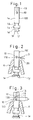
- Figs. 1 to 3 schematically show a plunger lead machining process according to the present invention.
- a raw material is machined to prepare a plunger blank 100 having a body 1a, a neck portion 1b, a face portion 1c, a neck portion 1d and a bottom end 1e, as shown in Fig. 1.
- This machining process may be identical to that of the prior art.
- the machining command data are prepared by making a program from the drawing and are encoded and read by the reader of an NC machine. This NC machine is used to perform the cutting operation.
- the plunger blank 100 thus prepared is bored with a port hole 10 in a predetermined position of its outer circumference and with an axial bore 13 from the upper end face of its body. Then, the plunger blank 100 is removed from the NC cutting machine and is hardened to have its entire hardness enhanced. The process till this step is identical to that of the prior art.
- the port hole 10 of this embodiment is made blind.
- the hardened plunger blank 100 is attached to the spindle end 4 of an NC machine such as an NC grinder, as shown in Fig. 2, and is additionally machined in a chucked state to form a shallow hole 110 which overlaps the lower end of the aforementioned port hole 10.
- an NC machine such as an NC grinder
- Fig. 4 shows the spindle end 4 and the machining state in detail.
- an inner chuck 41 having a positioning rod 40 fitted axially movably therein, there is arranged through a guide sleeve 42 a three-split outer chuck 43, which is fastened by a fastening sleeve 44 to be moved by a hydraulic actuator 45.
- the spindle end 4 is made rotatable.
- Reference numeral 3 designates a machining head which is carried by a cutter carriage and equipped at its leading end with a cutter (e.g., a grind stone or a cutting tool) 30. The machining head 3 is moved in the axial directions and in the radial directions.
- the aforementioned hardened plunger blank 100 is supported to have the bottom face 1f of its bottom end 1e abutting against the upper end of the positioning rod 40.
- the inner chuck 41 is fastened to chuck the circumference of the bottom end 1e.
- the fastening sleeve 44 is actuated by the actuator 45 to shrink the outer chuck 43 radially.
- the outer chuck 43 chucks the body 1a on its inner wall 430 so that the plunger blank 100 is firmly held and fixed in an upright position.
- the shallow hole 110 is machined.
- the shallow hole 110 is formed into a crescent shape having a smaller curvature than that of the port hole 10 and its lowermost point located on the longitudinal center line CL of the port hole 10.
- the combined shape of the port hole 10 and the shallow hole 110 exhibits a shape similar to a keyhole in a front elevation.
- the shallow hole 110 has its axial leading end merging smoothly into the inner wall of the port hole 10 along an arcuate or straight line.
- the shallow hole 110 is meant to have a smaller depth than that of the port hole 10.
- the size of the shallow hole 110 is unable to function as an effective machining reference point and difficult to machine, if it is too small. If too large, however, the shallow hole 110 may possibly affect the fuel flow adversely.
- the size (i.e., the radial depth) D1 of the shallow hole 110 from the lower end of the port hole 10 to the lowermost point of the arc is desired to fall within a range of 1/20 to 1/50 of the diameter of the port hole 10, as shown in Fig. 6.
- the axial size (i.e., the axial depth) of the shallow hole 110 from the entrance of the port hole 10 is desired to fall within a range of 1/3 to 5/6 of the depth of the port hole 10, if this hole 10 is blind.
- the spindle and the machining head 3 are relatively controlled, while the chucked state of Fig. 4 being held, to machine a longitudinal groove 11 having a predetermined length with the cutter 30 with reference of the lower end edge of the shallow hole 110.
- the longitudinal groove 11 is indicated by phantom lines in Fig. 6.
- Fig. 3 shows the state in which this machining operation is completed.
- a second lead 120 angularly displaced is machined subsequent to the foregoing lead 12. Then, a radial bore 14 extending through the body 1a is bored in the longitudinal groove 11 above the lead branching position.
- the size required to be functionally accurate is the length L2, as shown in Figs. 3 and 7, but the size from the lower end edge of the shallow hole 110 to the bottom face 1f of the bottom end 1e may disperse. This is because, the latter size can be adjusted by means of a shim when the fuel injection pump is adjusted.
- the radial bore 14 leading to the longitudinal bore 13 is formed close to the upper end of the longitudinal groove 11.
- this mode of embodiment should not limit the present invention.
- the port hole 10 may be modified, as in Fig. 8, into a through bore which is reached by the axial bore 13.
- the radial bore 14 may be formed at the first step.
- a rod made of high-carbon chromium bearing steel and having a diameter of 15 mm was machined to prepare a plunger blank.
- the plunger blank was machined to form an axial bore having a diameter of 3.5 mm and a depth of 2.6 mm from the top face and a port hole having a diameter of 3.5 mm and a substantial depth of 1.5 mm in a position at a distance of 64 mm from the bottom end.
- the plunger blank thus prepared was hardened to have a hardness of HRC63.
- the plunger blank was chucked by the spindle end of a vertical NC grinding machine, as shown in Fig. 4, to slot a shallow hole at the lower edge of the port hole.
- the cutter used was an electrodeposited grinding wheel having a diameter of 2.5 mm and was fed by 0.6 mm at a speed of 10 mm/min.
- the shallow hole had a crescent shape, as viewed in front elevation, and had a depth D2 of 1.0 mm, as taken in the axial direction of the port hole, and a radial depth D1 of 0.1 mm, as taken from the lower end of the port hole.
- the spindle end and the cutter carriage were controlled with the machining reference point of the lower end of the shallow hole to machine a longitudinal groove having a width of 3 mm, a cut of 1.5 mm and a length of 13mm and then to machine a first lead having an angle of 40 degrees, a width of 3 mm and a length of 8 mm and a second lead having an angle of 52 degrees, a width of 3 mm and a length of 3 mm in accordance with the program.
- One hundreds of plungers were manufactured by the process thus far described.
Landscapes
- Engineering & Computer Science (AREA)
- Chemical & Material Sciences (AREA)
- Combustion & Propulsion (AREA)
- Mechanical Engineering (AREA)
- General Engineering & Computer Science (AREA)
- Fuel-Injection Apparatus (AREA)
Claims (6)
- Verfahren zur Bearbeitung eines Kolbenrohlings (100), der einen Körper (1a), einen ersten Halsbereich (1b), einen Stirnbereich (1c), einen zweiten Halsbereich (1d) und ein Bodenende (1e) aufweist, in einen Kolben zur Verwendung in einer in-line-Kraftstoffeinspritzpumpe des Typs mit variabler Kraftstoffeinspritzmenge, enthaltend:
einen ersten Schritt der maschinellen Herstellung von sowohl einer axialen Bohrung (13) in dem Körper (1a) des Kolbenrohlings (100), welcher noch nicht gehärtet ist, von der oberen Endfläche desselben und einer Mündungsbohrung (10) an einer vorgegebenen Position des äußeren Umfangs des Körpers (1a), und dann Härten des Kolbenrohlings (100), um die Härte zu vergrößern;
weitere Schritte enthaltend einen Schritt der maschinellen Herstellung von sowohl einer longitudinalen Nut (11) in dem äußeren Umfang des gehärteten Kolbenrohlings (100) und einer Steuerkante (12) von einem vorgegebenen Punkt der longitudinalen Nut (11) in einer NC-Maschine mit einer gegebenen Bearbeitungsreferenz zum Einstellen einer effektiven Hubgröße (L₂),
dadurch gekennzeichnet, daß die weiteren Schritte enthalten:
einen zweiten Schritt des zusätzlichen maschinellen Herstellens einer oberflächlichen Öffnung (110) unter Überlappung des unteren Endes der Mündungsbohrung (10), durch Fixieren des gehärteten Kolbenrohlings (100) in der NC-Maschine und durch Schneiden des Körpers (1a) mit einem Schneidwerkzeug (30); und
einen dritten Schritt der Durchführung der maschinellen Herstellung der longitudinalen Nut (11) mit der Bearbeitungsreferenz der oberflächlichen Öffnung (110), wobei der fixierte Zustand des zweiten Schritts beibehalten wird, und Durchführung der maschinellen Herstellung der Steuerkante (12) mit der Bearbeitungsreferenz der oberflächlichen Öffnung (110). - Verfahren nach Anspruch 1, bei dem die Mündungsbohrung (10) blind hergestellt wird, während die oberflächliche Öffnung (110) mittels einer Schleifmaschine oder eines Schneidwerkzeugs als Schlitz ausgeführt wird, so daß sie in eine Halbmondform gebracht wird, die eine kleinere Krümmung hat als die der Mündungsbohrung (10) und deren unterster Punkt auf der longitudinalen Mittellinie (CL) der Mündungsbohrung (10) befindlich ist.
- Verfahren nach Anspruch 1 oder 2, bei dem der dritte Schritt weiterhin eine maschinelle Herstellung einer Radialbohrung (14) enthält.
- Verfahren nach Anspruch 1, bei dem die Mündungsbohrung (10) sich durch den Körper (1a) erstreckt.
- Verfahren nach Anspruch 1, bei dem der dritte Schritt weiterhin die maschinelle Herstellung einer zweiten Steuerkante (120) enthält mit einem geänderten Winkel auf die Steuerkante (12) folgend.
- Verfahren nach Anspruch 1, bei dem in den zweiten und dritten Schritten der gehärtete Kolbenrohling mit seinem Bodenende (1e) durch das obere Ende einer Positionierungsstange (40) einer Spindel (4) einer NC-Maschine getragen und an seinen Seiten durch ein inneres Spannfutter (41) fixiert und mit seinem Körper (1a) durch ein äußeres Spannfutter (43) fixiert wird.
Applications Claiming Priority (2)
| Application Number | Priority Date | Filing Date | Title |
|---|---|---|---|
| JP3329740A JP2884454B2 (ja) | 1991-11-20 | 1991-11-20 | 燃料噴射ポンプ用プランジャのリード加工法 |
| JP329740/91 | 1991-11-20 |
Publications (2)
| Publication Number | Publication Date |
|---|---|
| EP0543383A1 EP0543383A1 (de) | 1993-05-26 |
| EP0543383B1 true EP0543383B1 (de) | 1995-03-01 |
Family
ID=18224752
Family Applications (1)
| Application Number | Title | Priority Date | Filing Date |
|---|---|---|---|
| EP92119747A Expired - Lifetime EP0543383B1 (de) | 1991-11-20 | 1992-11-19 | Verfahren zur Bearbeitung von Steuerkanten auf den Kolben der Kraftstoffeinspritzpumpen |
Country Status (5)
| Country | Link |
|---|---|
| US (1) | US5267396A (de) |
| EP (1) | EP0543383B1 (de) |
| JP (1) | JP2884454B2 (de) |
| KR (1) | KR960008784B1 (de) |
| DE (1) | DE69201551T2 (de) |
Families Citing this family (3)
| Publication number | Priority date | Publication date | Assignee | Title |
|---|---|---|---|---|
| JPH06147054A (ja) * | 1992-10-30 | 1994-05-27 | Zexel Corp | プランジャバレルの製造方法 |
| KR200460498Y1 (ko) * | 2011-02-16 | 2012-05-25 | 김대읍 | 찌꺼기 제거용 주걱 |
| CN114683008B (zh) * | 2022-04-24 | 2023-07-21 | 成都飞机工业(集团)有限责任公司 | 一种高精度同轴耳片锥孔的加工方法 |
Family Cites Families (17)
| Publication number | Priority date | Publication date | Assignee | Title |
|---|---|---|---|---|
| GB1084198A (de) * | 1900-01-01 | |||
| US3123006A (en) * | 1964-03-03 | Injector plunger | ||
| US2696786A (en) * | 1952-01-21 | 1954-12-14 | Caterpillar Tractor Co | Fuel injection pump plunger |
| US3833988A (en) * | 1972-08-23 | 1974-09-10 | J Tobias | Method of making spool valves |
| JPS5118011B2 (de) * | 1972-12-06 | 1976-06-07 | ||
| US4163634A (en) * | 1977-11-25 | 1979-08-07 | Caterpillar Tractor Co. | Fuel pump plunger |
| AT374570B (de) * | 1982-04-27 | 1984-05-10 | Steyr Daimler Puch Ag | Einspritzkolbenpumpe fuer dieselmotoren |
| DE3347430A1 (de) * | 1983-12-29 | 1985-07-11 | Robert Bosch Gmbh, 7000 Stuttgart | Kraftstoffeinspritzpumpe fuer brennkraftmaschinen |
| FR2562165B1 (fr) * | 1984-03-29 | 1988-06-17 | Semt | Procede et dispositif d'amortissement des ondes de pression hydrauliques et d'ecretage des variations de pression dans les conduits d'alimentation d'une pompe d'injection de combustible |
| JPH0635863B2 (ja) * | 1985-03-25 | 1994-05-11 | 三菱自動車工業株式会社 | 燃料噴射ポンプ |
| JPS6135727A (ja) * | 1984-07-26 | 1986-02-20 | 株式会社クボタ | 温室用温調装置 |
| JPS61123756A (ja) * | 1984-11-16 | 1986-06-11 | Diesel Kiki Co Ltd | 燃料噴射ポンプ |
| DE3724409A1 (de) * | 1986-10-31 | 1988-05-19 | Bosch Gmbh Robert | Kraftstoffeinspritzpumpe fuer brennkraftmaschinen |
| DE3723698C2 (de) * | 1987-07-17 | 1995-04-27 | Bosch Gmbh Robert | Kraftstoffeinspritzventil sowie Verfahren zu dessen Einstellung |
| JPH01117981A (ja) * | 1987-10-31 | 1989-05-10 | Diesel Kiki Co Ltd | プリストローク制御機構付き燃料噴射ポンプ |
| IN171906B (de) * | 1988-07-19 | 1993-02-06 | Motor Ind Co Ltd | |
| DE3914582A1 (de) * | 1989-05-03 | 1990-11-08 | Kloeckner Humboldt Deutz Ag | Brennstoffeinspritzvorrichtung |
-
1991
- 1991-11-20 JP JP3329740A patent/JP2884454B2/ja not_active Expired - Lifetime
-
1992
- 1992-11-17 US US07/977,813 patent/US5267396A/en not_active Expired - Fee Related
- 1992-11-18 KR KR1019920021627A patent/KR960008784B1/ko not_active Expired - Fee Related
- 1992-11-19 DE DE69201551T patent/DE69201551T2/de not_active Expired - Fee Related
- 1992-11-19 EP EP92119747A patent/EP0543383B1/de not_active Expired - Lifetime
Also Published As
| Publication number | Publication date |
|---|---|
| JPH05141324A (ja) | 1993-06-08 |
| JP2884454B2 (ja) | 1999-04-19 |
| KR930010368A (ko) | 1993-06-22 |
| US5267396A (en) | 1993-12-07 |
| KR960008784B1 (ko) | 1996-07-03 |
| DE69201551T2 (de) | 1995-10-19 |
| EP0543383A1 (de) | 1993-05-26 |
| DE69201551D1 (de) | 1995-04-06 |
Similar Documents
| Publication | Publication Date | Title |
|---|---|---|
| US4545706A (en) | Method and machine for machining the surface of a valve seat | |
| DE60038459T2 (de) | Brillenglaslinsen bearbeitungsverfahren und vorrichtung | |
| JP2682813B2 (ja) | 穴の始端の面取り部を精密研削する方法 | |
| CN108672806A (zh) | 一种硬齿面花键孔的刮削拉刀 | |
| US11623283B2 (en) | Turning insert for metal cutting | |
| EP0543383B1 (de) | Verfahren zur Bearbeitung von Steuerkanten auf den Kolben der Kraftstoffeinspritzpumpen | |
| US9539658B2 (en) | Reaming tool and method for the production thereof | |
| US3930482A (en) | Fuel injection piston and method of its manufacture | |
| JP4112471B2 (ja) | シリンダヘッドのバルブシート面及びバルブガイド穴の加工方法及び加工装置 | |
| CN110587223B (zh) | 一种薄壁高位置精度孔系零件加工方法 | |
| US4827673A (en) | Process and device for grinding moulding blanks to size | |
| US11565356B2 (en) | Method for producing a cutting head | |
| EP0404407A1 (de) | Kraftstoffeinspritzdüse | |
| CN205362713U (zh) | 一种用于柴油机体凸轮轴孔加工的纠偏复合刀具 | |
| CN205572145U (zh) | 一种精加工挺柱孔珩磨刀 | |
| EP3577336B1 (de) | Verfahren zum erreichen eines finalen luftspalts und parallelismus eines kraftstoffeinspritzsteuerventils | |
| CN105458311B (zh) | 用于柴油机体凸轮轴孔加工的纠偏复合刀具 | |
| US20220281017A1 (en) | Method for producing a milled part with a countersinking tool and countersinking tool | |
| CN106541193B (zh) | 精密异形高压油道加工方法 | |
| CN112846342A (zh) | 一种组合式高强度插刀 | |
| CN218362443U (zh) | 一种具有辅助定位导向装置的筒式拉刀 | |
| JP2002331447A (ja) | 燃料噴射ノズルのシート部研削加工方法 | |
| JPH0874704A (ja) | 内燃機関用の燃料噴射ポンプ | |
| KR20200005855A (ko) | 실린더 헤드 및 그 제조방법 | |
| JPS629834A (ja) | バルブ停止機構付エンジンのカムシヤフト製造方法 |
Legal Events
| Date | Code | Title | Description |
|---|---|---|---|
| PUAI | Public reference made under article 153(3) epc to a published international application that has entered the european phase |
Free format text: ORIGINAL CODE: 0009012 |
|
| AK | Designated contracting states |
Kind code of ref document: A1 Designated state(s): DE FR |
|
| 17P | Request for examination filed |
Effective date: 19931108 |
|
| 17Q | First examination report despatched |
Effective date: 19931210 |
|
| GRAA | (expected) grant |
Free format text: ORIGINAL CODE: 0009210 |
|
| RIN1 | Information on inventor provided before grant (corrected) |
Inventor name: MORI, KOITI, C/O HIGASHI-MATSUYAMA KOJO Inventor name: NAKAGAWA, TOSHIHIRO, C/O HIGASHI-MATSUYAMA KOJO Inventor name: WADA, YUKIO, C/O HIGASHI-MATSUYAMA KOJO |
|
| AK | Designated contracting states |
Kind code of ref document: B1 Designated state(s): DE FR |
|
| REF | Corresponds to: |
Ref document number: 69201551 Country of ref document: DE Date of ref document: 19950406 |
|
| ET | Fr: translation filed | ||
| PLBE | No opposition filed within time limit |
Free format text: ORIGINAL CODE: 0009261 |
|
| STAA | Information on the status of an ep patent application or granted ep patent |
Free format text: STATUS: NO OPPOSITION FILED WITHIN TIME LIMIT |
|
| 26N | No opposition filed | ||
| PGFP | Annual fee paid to national office [announced via postgrant information from national office to epo] |
Ref country code: FR Payment date: 20001110 Year of fee payment: 9 |
|
| PGFP | Annual fee paid to national office [announced via postgrant information from national office to epo] |
Ref country code: DE Payment date: 20001113 Year of fee payment: 9 |
|
| REG | Reference to a national code |
Ref country code: FR Ref legal event code: CD Ref country code: FR Ref legal event code: CA |
|
| PG25 | Lapsed in a contracting state [announced via postgrant information from national office to epo] |
Ref country code: DE Free format text: LAPSE BECAUSE OF NON-PAYMENT OF DUE FEES Effective date: 20020702 |
|
| PG25 | Lapsed in a contracting state [announced via postgrant information from national office to epo] |
Ref country code: FR Free format text: LAPSE BECAUSE OF NON-PAYMENT OF DUE FEES Effective date: 20020730 |
|
| REG | Reference to a national code |
Ref country code: FR Ref legal event code: ST |
|
| REG | Reference to a national code |
Ref country code: FR Ref legal event code: ST |