EP3577336B1 - Verfahren zum erreichen eines finalen luftspalts und parallelismus eines kraftstoffeinspritzsteuerventils - Google Patents
Verfahren zum erreichen eines finalen luftspalts und parallelismus eines kraftstoffeinspritzsteuerventils Download PDFInfo
- Publication number
- EP3577336B1 EP3577336B1 EP18702475.7A EP18702475A EP3577336B1 EP 3577336 B1 EP3577336 B1 EP 3577336B1 EP 18702475 A EP18702475 A EP 18702475A EP 3577336 B1 EP3577336 B1 EP 3577336B1
- Authority
- EP
- European Patent Office
- Prior art keywords
- armature
- face
- upper face
- control valve
- top face
- Prior art date
- Legal status (The legal status is an assumption and is not a legal conclusion. Google has not performed a legal analysis and makes no representation as to the accuracy of the status listed.)
- Active
Links
Images

Classifications
-
- F—MECHANICAL ENGINEERING; LIGHTING; HEATING; WEAPONS; BLASTING
- F02—COMBUSTION ENGINES; HOT-GAS OR COMBUSTION-PRODUCT ENGINE PLANTS
- F02M—SUPPLYING COMBUSTION ENGINES IN GENERAL WITH COMBUSTIBLE MIXTURES OR CONSTITUENTS THEREOF
- F02M47/00—Fuel-injection apparatus operated cyclically with fuel-injection valves actuated by fluid pressure
- F02M47/02—Fuel-injection apparatus operated cyclically with fuel-injection valves actuated by fluid pressure of accumulator-injector type, i.e. having fuel pressure of accumulator tending to open, and fuel pressure in other chamber tending to close, injection valves and having means for periodically releasing that closing pressure
- F02M47/022—Mechanically actuated valves draining the chamber to release the closing pressure
-
- B—PERFORMING OPERATIONS; TRANSPORTING
- B23—MACHINE TOOLS; METAL-WORKING NOT OTHERWISE PROVIDED FOR
- B23K—SOLDERING OR UNSOLDERING; WELDING; CLADDING OR PLATING BY SOLDERING OR WELDING; CUTTING BY APPLYING HEAT LOCALLY, e.g. FLAME CUTTING; WORKING BY LASER BEAM
- B23K26/00—Working by laser beam, e.g. welding, cutting or boring
- B23K26/36—Removing material
-
- F—MECHANICAL ENGINEERING; LIGHTING; HEATING; WEAPONS; BLASTING
- F02—COMBUSTION ENGINES; HOT-GAS OR COMBUSTION-PRODUCT ENGINE PLANTS
- F02M—SUPPLYING COMBUSTION ENGINES IN GENERAL WITH COMBUSTIBLE MIXTURES OR CONSTITUENTS THEREOF
- F02M47/00—Fuel-injection apparatus operated cyclically with fuel-injection valves actuated by fluid pressure
- F02M47/02—Fuel-injection apparatus operated cyclically with fuel-injection valves actuated by fluid pressure of accumulator-injector type, i.e. having fuel pressure of accumulator tending to open, and fuel pressure in other chamber tending to close, injection valves and having means for periodically releasing that closing pressure
- F02M47/027—Electrically actuated valves draining the chamber to release the closing pressure
-
- F—MECHANICAL ENGINEERING; LIGHTING; HEATING; WEAPONS; BLASTING
- F02—COMBUSTION ENGINES; HOT-GAS OR COMBUSTION-PRODUCT ENGINE PLANTS
- F02M—SUPPLYING COMBUSTION ENGINES IN GENERAL WITH COMBUSTIBLE MIXTURES OR CONSTITUENTS THEREOF
- F02M61/00—Fuel-injectors not provided for in groups F02M39/00 - F02M57/00 or F02M67/00
- F02M61/16—Details not provided for in, or of interest apart from, the apparatus of groups F02M61/02 - F02M61/14
- F02M61/168—Assembling; Disassembling; Manufacturing; Adjusting
-
- F—MECHANICAL ENGINEERING; LIGHTING; HEATING; WEAPONS; BLASTING
- F02—COMBUSTION ENGINES; HOT-GAS OR COMBUSTION-PRODUCT ENGINE PLANTS
- F02M—SUPPLYING COMBUSTION ENGINES IN GENERAL WITH COMBUSTIBLE MIXTURES OR CONSTITUENTS THEREOF
- F02M63/00—Other fuel-injection apparatus having pertinent characteristics not provided for in groups F02M39/00 - F02M57/00 or F02M67/00; Details, component parts, or accessories of fuel-injection apparatus, not provided for in, or of interest apart from, the apparatus of groups F02M39/00 - F02M61/00 or F02M67/00; Combination of fuel pump with other devices, e.g. lubricating oil pump
- F02M63/0012—Valves
- F02M63/0014—Valves characterised by the valve actuating means
- F02M63/0015—Valves characterised by the valve actuating means electrical, e.g. using solenoid
- F02M63/0017—Valves characterised by the valve actuating means electrical, e.g. using solenoid using electromagnetic operating means
- F02M63/0021—Valves characterised by the valve actuating means electrical, e.g. using solenoid using electromagnetic operating means characterised by the arrangement of mobile armatures
-
- F—MECHANICAL ENGINEERING; LIGHTING; HEATING; WEAPONS; BLASTING
- F02—COMBUSTION ENGINES; HOT-GAS OR COMBUSTION-PRODUCT ENGINE PLANTS
- F02M—SUPPLYING COMBUSTION ENGINES IN GENERAL WITH COMBUSTIBLE MIXTURES OR CONSTITUENTS THEREOF
- F02M63/00—Other fuel-injection apparatus having pertinent characteristics not provided for in groups F02M39/00 - F02M57/00 or F02M67/00; Details, component parts, or accessories of fuel-injection apparatus, not provided for in, or of interest apart from, the apparatus of groups F02M39/00 - F02M61/00 or F02M67/00; Combination of fuel pump with other devices, e.g. lubricating oil pump
- F02M63/0012—Valves
- F02M63/0031—Valves characterized by the type of valves, e.g. special valve member details, valve seat details, valve housing details
- F02M63/0033—Lift valves, i.e. having a valve member that moves perpendicularly to the plane of the valve seat
- F02M63/0035—Poppet valves, i.e. having a mushroom-shaped valve member that moves perpendicularly to the plane of the valve seat
-
- F—MECHANICAL ENGINEERING; LIGHTING; HEATING; WEAPONS; BLASTING
- F02—COMBUSTION ENGINES; HOT-GAS OR COMBUSTION-PRODUCT ENGINE PLANTS
- F02M—SUPPLYING COMBUSTION ENGINES IN GENERAL WITH COMBUSTIBLE MIXTURES OR CONSTITUENTS THEREOF
- F02M2200/00—Details of fuel-injection apparatus, not otherwise provided for
- F02M2200/80—Fuel injection apparatus manufacture, repair or assembly
- F02M2200/8069—Fuel injection apparatus manufacture, repair or assembly involving removal of material from the fuel apparatus, e.g. by punching, hydro-erosion or mechanical operation
Definitions
- a needle valve member reciprocally moves along a main axis to alternatively enable or prevent fuel injection.
- the pressure in a control chamber associated to said needle is varied by alternating a control valve having a body extending about a main axis from an axially transverse top face to an opposed bottom face and being provided with an axial hydraulic bore opening in a recess defining a chamber opening in said top face.
- the control valve further comprises a spool comprising a thick disc magnetic armature having opposed upper and lower faces and, a stem press-fitted in an axial central drilling of the armature.
- Said spool is arranged in the body in a rest position wherein the stem is axially guided in the hydraulic bore and the armature lies in the chamber the upper face of the armature being slightly recessed from the top face of the body.
- the ablating step comprises:
- the tilt height is of constant depth.
- the constant depth may be about 1 ⁇ m.
- the band comprising the highest point of the line of greatest slope, the highest point band is ablated several time and the band comprising to the lowest point of the line of greatest slope, the lowest point band, is ablated only one time.
- the ablating step is performed in using a picosecond or a femtosecond pulsed laser.
- the control valve is further provided with a spool comprising a thick disc magnetic armature having an axial central drilling opening at each ends in a planar transverse upper face and an opposed lower face and, a stem press-fitted in said central drilling, the spool being arranged in the body in a rest position wherein, the stem, is axially guided in the hydraulic bore, and the armature is lying in the chamber, the armature upper face being slightly recessed from the body top face.
- the armature upper face is ablated as per the method previously described.
- the final air gap tolerance of said control valve is about 2 ⁇ m and the parallelism of the armature upper face and the body top face is about 10 ⁇ m.
- a fuel injector 10 is provided with a control valve 12 enabling pressure to vary in a control chamber such that, a needle valve moves and open or close spray holes arranged in a nozzle of the injector 10.
- the example is chosen from a diesel fuel injector.
- the control valve 12 has a body 14 in which is arranged a moving spool 16.
- the body 14 is a cylindrical member extending along a main axis X between a top transverse face 18 and an opposed lower face 20.
- a recess 22 forming a chamber 22 opening in the top face 18 and, an hydraulic bore 24 extending along a main axis X and opening at a lower end in the lower face 20 and, at an upper end in the bottom 26 of the recess 22.
- the control valve 12 is pressed between an actuation member and the nozzle assembly, the valve body top face 18 being in sealing surface contact against a lower face of said actuation member.
- the body top face 18 is provided with sealing areas adapted to be in said sealing contact with said actuation member, and with larger area in recess to said sealing areas.
- the sealing areas are for instance an annular ring face surrounding the opening of the chamber 22 and three angular sectors arranged on the peripheral edge of said top face.
- said sealing areas are identified as the body top face 18.
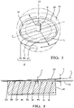
- the magnetic armature 28 is entirely in the chamber 22, the armature upper face 30 being parallel and slightly recessed relative to said top face 18 (sealing areas) by a final air gap (FAG). Positioning tolerances are extremely tight and, as shown on the figure, a parallelism of 10 ⁇ m and a recess of 2 ⁇ m between the armature upper face 30 and the body top face 18 are realistic example.
- the upper face 30 of the armature is finished in following a method 100 of ablation by parallel bands using an ultra-short pulse laser such as a picosecond or a femtosecond pulsed laser.
- an ultra-short pulse laser such as a picosecond or a femtosecond pulsed laser.
- the method 100 initial step is to measure 110 the relative position from the armature upper face 30 and the body top face 18 and, to determine the actual parallelism error between said faces.
- a measuring device can be either of contact type using an arrangement of positional probes across the body top face 18 to set the datum and the armature upper face 30 to construct a plane.
- Another option is to use a non-contact type such as optical interferometry to achieve the same result.
- the FAG tolerance achievement is expected to be as much as ⁇ 3 ⁇ m and the parallelism 15 ⁇ m.
- the body top face 18 is the reference face and, both faces 18, 30 being planar at start, said parallelism error is an angular tilt of the armature upper face 30 relative to the body top face 18.
- said tilt height H is divided 116 in a plurality of individual ablating pass depth D.
- a preferred dividing step is to have constant depth D of about 1 ⁇ m while other values may be chosen.
- Said division also determines a number of parallel bands B on the upper face 30, said bands B being perpendicular to the line of greatest slope L.
- Said method steps 110-116 prepare the operational step coming next.
- Said operational step consist in ablating 120 the armature upper face 30, said ablating step 120 being performed by successive passes, each of the depth D previously calculated in step 114. Said successive passes are performed band after bands B of the upper face 30.
- the ablating step 120 is started by a first band B1 comprising the highest point of the line of greatest slope L where a depth D of surface material is removed from this first band B1.
- the following step is to ablate a second band B2, neighbour to the first band B1, as well as ablating the first band B1.
- a depth D of surface material has been removed once from the second band B2 and twice form the first band B1. This continues as long as the last band B comprising the lowest point of the line L is not ablated. Therefore, if the upper face 30 comprises N bands B, the first band B1 is ablated N times for a total depth of N.D and the last band "BN" is ablated just one time for a depth of 1.D.
- the ablating operation is performed by having the entire area of a band scanned by the beam of said ultra-short pulse laser which focuses on the surface of the band.
- Tests have been performed programing the laser to scan each band by moving along the beam along the transverse tilt axis Y, scanning a complete band requiring several of said transverse displacements, offsetting the laser beam along the line of greatest slope L at the end of each transverse displacement when reaching the periphery of the armature upper face 30.
- a scanning speed of few meters per second, five for instance, has shown good results.
- the scanning speed may be varied between starting and finishing ablation of a band. Slowing down said scanning speed enables the laser beam to focus longer on certain area of the band than on others and then to remove more material on said areas. The speed is then kept constant as long as ablating a line, or linear area, and the laser translating along the transverse axis Y and, when offsetting the beam in order to change line, the scanning speed may slightly reduce to enable the beam to remain longer on an area and then, remove more material.
- This process method 100 enables to achieve the required parallelism between the surfaces and also to adjust the final air gap.
Landscapes
- Engineering & Computer Science (AREA)
- Mechanical Engineering (AREA)
- Chemical & Material Sciences (AREA)
- Combustion & Propulsion (AREA)
- General Engineering & Computer Science (AREA)
- Physics & Mathematics (AREA)
- Electromagnetism (AREA)
- Fluid Mechanics (AREA)
- Manufacturing & Machinery (AREA)
- Optics & Photonics (AREA)
- Plasma & Fusion (AREA)
- Fuel-Injection Apparatus (AREA)
Claims (10)
- Verfahren (100) zum Erreichen eines abschließenden Luftspalts (final air gap - FAG) und einer Parallelität eines Steuerventils (12) einer Kraftstoffeinspritzdüse (10),wobei das Steuerventil (12) einen Körper (14) aufweist, der sich um eine Hauptachse (X) von einer obersten Querfläche (18) zu einer gegenüberliegenden unteren Fläche (20) erstreckt und mit einer axialen Hydraulikbohrung (24) versehen ist, die sich in einer Vertiefung öffnet, wobei die Vertiefung eine Kammer (22) definiert, die sich in der obersten Fläche (18) öffnet,wobei das Steuerventil (12) ferner mit einer Rolle (16) versehen ist, umfassend einen scheibenförmigen Magnetanker (28), der eine axiale zentrale Bohröffnung an jedem Ende in einer ebenen oberen Querfläche (30) und einer gegenüberliegenden unteren Fläche aufweist, und einen Schaft (34), der in der zentralen Bohrung befestigt ist,wobei die Rolle (16) in dem Körper (14) in einer Ruheposition angeordnet ist, wobei der Schaft (34) in der Hydraulikbohrung (24) axial geführt ist und der Anker (28) in der Kammer (22) liegt, wobei die obere Fläche (30) des Ankers leicht von der obersten Fläche (18) des Körpers vertieft ist, dadurch gekennzeichnet, dassdas Verfahren die folgenden Schritte umfasst:a) Messen (110) der tatsächlichen Position von der oberen Fläche (30) des Ankers und der obersten Fläche (18) des Körpers und Bestimmen des tatsächlichen Parallelitätsfehlers zwischen den Flächen (18, 30), wobei der tatsächliche Parallelitätsfehler die Winkelneigung der ebenen oberen Querfläche (30) relativ zu der obersten Fläche (18) ist, wobei das Messen (110) umfasst: a1) Bestimmen (112) der Neigungsachse (Y) und der Linie des größten Gefälles (L) der oberen Fläche (30) des Ankers, wobei die Neigungsachse (Y) und die Linie (L) senkrecht zueinander sind, wobei die Neigungsachse (Y) die Querachse ist, um die die obere Fläche (30) abgewinkelt ist;a2) Berechnen (114) einer Neigungshöhe (H) zwischen den Enden der Linie des größten Gefälles (L), wobei die Neigungshöhe (H) der Abstand ist, der entlang der Hauptachse (X) von dem höchsten Punkt der Linie (L) zu dem niedrigsten Punkt der Linie (L) gemessen wird, wobei der höchste Punkt näher an der obersten Fläche (18) liegt und der niedrigste Punkt weiter in die Kammer (22) vertieft ist; unda3) Teilen (116) der Neigungshöhe (H) in einzelne Abtragungsdurchlauftiefen (D);wobei das Verfahren ferner umfasst: b) Abtragen (120) des Ankers, um die Neigungshöhe und den Parallelitätsfehler durch ein Erzeugen einer abgetragenen oberen Fläche (32) parallel zu der obersten Fläche (18) des Körpers zu korrigieren, wobei der Abstand von der abgetragenen oberen Fläche (32) zu der obersten Fläche (18) des Körpers ein abschließender Luftspalt (FAG) ist.
- Verfahren (100) nach Anspruch 1, wobei der Abtragungsschritt (120) umfasst:
b1) Abtragen (120) des Ankers durch aufeinanderfolgendes Durchlaufen der einzelnen Tiefe (D) und Erzeugen der abgetragenen Fläche (32) durch aufeinanderfolgendes Abtragen einer Vielzahl von parallelen Bändern (B), die sich entlang der Neigungsachse (Y) erstrecken. - Verfahren (100) nach Anspruch 2, wobei in dem Teilungsschritt (116) die Neigungshöhe (H) eine konstante Tiefe (D) aufweist.
- Verfahren (100) nach Anspruch 3, wobei die konstante Tiefe (D) etwa 1 µm beträgt.
- Verfahren (100) nach einem der Ansprüche 2 bis 4, wobei während des Ablationsschritts (120) das Band (B), das den höchsten Punkt der Linie des größten Gefälles (L) umfasst, das Band (B1) mit dem höchsten Punkt, mehrmals abgetragen wird, und das Band, das bis zu dem niedrigsten Punkt der Linie des größten Gefälles (L) umfasst, das Band mit dem niedrigsten Punkt, nur einmal abgetragen wird.
- Verfahren (100) nach Anspruch 5, wobei das Band (B1) mit dem höchsten Punkt so oft abgetragen wird, wie die Neigungshöhe (H) in Schritt (116) geteilt wurde.
- Verfahren (100) nach einem der vorhergehenden Ansprüche, wobei der Abtragungsschritt (120) unter Verwendung eines gepulsten Pikosekunden- oder Femtosekundenlasers durchgeführt wird.
- Steuerventil (12) einer Kraftstoffeinspritzdüse (10), wobei das Steuerventil (12) einen Körper (14) aufweist, der sich um eine Hauptachse (X) von einer obersten Querfläche (18) zu einer gegenüberliegenden unteren Fläche (20) erstreckt und mit einer axialen hydraulischen Bohrung (24) versehen ist, die sich in einer Vertiefung öffnet, wobei die Vertiefung eine Kammer (22) definiert, die sich in der obersten Fläche (18) öffnet,wobei das Steuerventil (12) ferner mit einer Rolle (16) versehen ist, umfassend einen scheibenförmigen Magnetanker (28), der eine axiale zentrale Bohröffnung an jedem Ende in einer ebenen oberen Querfläche (30) und einer gegenüberliegenden unteren Fläche aufweist, und einen Schaft (34), der in der zentralen Bohrung befestigt ist,wobei die Rolle (16) in dem Körper (14) in einer Ruheposition angeordnet ist, wobei der Schaft (34) in der Hydraulikbohrung (24) axial geführt ist und der Anker (28) in der Kammer (22) liegt, wobei die obere Fläche (30) des Ankers leicht von der obersten Fläche (18) des Körpers vertieft ist, dadurch gekennzeichnet, dassdie obere Fläche (30) des Ankers gemäß dem Verfahren (100) nach einem der vorstehenden Ansprüche abgetragen wird.
- Steuerventil (12) nach Anspruch 8, wobei der abschließende Luftspalt (FAG) etwa 2 µm beträgt und die Parallelität der oberen Fläche des Ankers und der obersten Fläche des Körpers etwa 10 µm beträgt.
- Kraftstoffeinspritzdüse (10), umfassend ein Steuerventil (12) nach einem der Ansprüche 8 oder 9.
Applications Claiming Priority (2)
| Application Number | Priority Date | Filing Date | Title |
|---|---|---|---|
| GB1701555.3A GB2559342A (en) | 2017-01-31 | 2017-01-31 | Method for achieving final air gap and parallelism of a fuel injector control valve |
| PCT/EP2018/052175 WO2018141696A1 (en) | 2017-01-31 | 2018-01-29 | Method for achieving final air gap and parallelism of a fuel injector control valve |
Publications (2)
| Publication Number | Publication Date |
|---|---|
| EP3577336A1 EP3577336A1 (de) | 2019-12-11 |
| EP3577336B1 true EP3577336B1 (de) | 2022-09-14 |
Family
ID=58462744
Family Applications (1)
| Application Number | Title | Priority Date | Filing Date |
|---|---|---|---|
| EP18702475.7A Active EP3577336B1 (de) | 2017-01-31 | 2018-01-29 | Verfahren zum erreichen eines finalen luftspalts und parallelismus eines kraftstoffeinspritzsteuerventils |
Country Status (4)
| Country | Link |
|---|---|
| US (1) | US11022081B2 (de) |
| EP (1) | EP3577336B1 (de) |
| GB (1) | GB2559342A (de) |
| WO (1) | WO2018141696A1 (de) |
Families Citing this family (1)
| Publication number | Priority date | Publication date | Assignee | Title |
|---|---|---|---|---|
| US20210379701A1 (en) * | 2020-06-08 | 2021-12-09 | Standex International Corporation | Laser engraving using stochastically generated laser pulse locations |
Family Cites Families (19)
| Publication number | Priority date | Publication date | Assignee | Title |
|---|---|---|---|---|
| US4978074A (en) * | 1989-06-21 | 1990-12-18 | General Motors Corporation | Solenoid actuated valve assembly |
| US5947442A (en) * | 1997-09-10 | 1999-09-07 | Cummins Engine Company, Inc. | Solenoid actuated valve assembly |
| JP4277158B2 (ja) * | 2000-04-11 | 2009-06-10 | 株式会社デンソー | 電磁弁及びそれを用いた燃料噴射装置 |
| DE10105368A1 (de) * | 2001-02-06 | 2002-08-29 | Siemens Ag | Kraftstoffeinspritzdüse für eine Brennkraftmaschine |
| DE10202324A1 (de) | 2002-01-23 | 2003-07-31 | Bosch Gmbh Robert | Magnetventil und Verfahren zu seiner Herstellung |
| JP4064934B2 (ja) * | 2004-02-27 | 2008-03-19 | 三菱重工業株式会社 | 電磁弁装置 |
| US20070138324A1 (en) * | 2005-12-20 | 2007-06-21 | Ibrahim Daniel R | Armature assembly with improved alignment capability |
| US7779854B2 (en) * | 2007-01-12 | 2010-08-24 | Caterpillar Inc | Valve member to armature coupling system and fuel injector using same |
| DE102008040015A1 (de) | 2008-06-30 | 2009-12-31 | Robert Bosch Gmbh | Magnetventil, Kraftstoff-Injektor sowie Herstellungsverfahren |
| US8459577B2 (en) * | 2008-07-08 | 2013-06-11 | Caterpillar Inc. | Decoupled valve assembly and fuel injector using same |
| US8083206B2 (en) * | 2008-07-08 | 2011-12-27 | Caterpillar Inc. | Precision ground armature assembly for solenoid actuator and fuel injector using same |
| US20100007224A1 (en) * | 2008-07-08 | 2010-01-14 | Caterpillar Inc. | Precision ground stator assembly for solenoid actuator and fuel injector using same |
| US8316826B2 (en) * | 2009-01-15 | 2012-11-27 | Caterpillar Inc. | Reducing variations in close coupled post injections in a fuel injector and fuel system using same |
| US8368661B2 (en) * | 2009-07-13 | 2013-02-05 | Apple Inc. | Method for fabricating touch sensor panels |
| JP2011125914A (ja) * | 2009-12-18 | 2011-06-30 | Denso Corp | 周期構造の形成方法及び周期構造を有する燃料噴射装置 |
| EP2771562B1 (de) * | 2011-10-26 | 2019-09-18 | CPT Group GmbH | Ventilanordnung für ein einspritzventil und einspritzventil |
| US20130248612A1 (en) * | 2012-03-26 | 2013-09-26 | Caterpillar Inc. | Solenoid Actuator And Fuel Injector Using Same |
| DE102012218325A1 (de) * | 2012-10-09 | 2014-04-10 | Continental Automotive Gmbh | Aktuatoreinheit, insbesondere für die Einspritzung eines Kraftstoffs in einen Brennraum einer Verbrennungskraftmaschine |
| CN107002620B (zh) * | 2014-12-11 | 2019-06-25 | 德尔福国际业务卢森堡公司 | 控制阀组件 |
-
2017
- 2017-01-31 GB GB1701555.3A patent/GB2559342A/en not_active Withdrawn
-
2018
- 2018-01-29 US US16/482,496 patent/US11022081B2/en active Active
- 2018-01-29 WO PCT/EP2018/052175 patent/WO2018141696A1/en not_active Ceased
- 2018-01-29 EP EP18702475.7A patent/EP3577336B1/de active Active
Also Published As
| Publication number | Publication date |
|---|---|
| EP3577336A1 (de) | 2019-12-11 |
| GB201701555D0 (en) | 2017-03-15 |
| US11022081B2 (en) | 2021-06-01 |
| WO2018141696A1 (en) | 2018-08-09 |
| US20200011278A1 (en) | 2020-01-09 |
| GB2559342A (en) | 2018-08-08 |
Similar Documents
| Publication | Publication Date | Title |
|---|---|---|
| US6138055A (en) | Controlled machining of combustion chambers, gears and other surfaces | |
| US4559684A (en) | Controlled machining of combustion chambers, gears and other surfaces | |
| JP2683502B2 (ja) | 工作物の表面を精密加工するための方法 | |
| DE102020206089A1 (de) | Laserbearbeitungsgerät, laserbearbeitungsverfahren und korrekturdaten-erzeugungsverfahren | |
| JP2682813B2 (ja) | 穴の始端の面取り部を精密研削する方法 | |
| EP3577336B1 (de) | Verfahren zum erreichen eines finalen luftspalts und parallelismus eines kraftstoffeinspritzsteuerventils | |
| US8360338B2 (en) | Fuel injection valve and machining method for nozzle | |
| US5940302A (en) | Controlled machining of combustion chambers, gears and other surfaces | |
| EP3883720B1 (de) | Verfahren zur laserbearbeitung und laserbearbeitungssystem zur durchführung des verfahrens | |
| JP6496924B2 (ja) | ワーク円筒部の形状測定方法および形状測定装置 | |
| US5012574A (en) | Controlled machining of combustion chambers gears and other surfaces | |
| US20140147220A1 (en) | Milling/surfacing method and device | |
| KR102279990B1 (ko) | 호닝 툴 및 호닝 머신을 사용하여 원통형 보어를 원추화하도록 설계되고 배치된 회전 대칭의 비-원통형 보어를 생성하기 위한 방법 | |
| WO2019065408A1 (ja) | 燃料噴射弁 | |
| JP2020172944A (ja) | 燃料噴射弁 | |
| Tai et al. | Surface variation reduction for face milling based on high-definition metrology | |
| US11619200B2 (en) | Fuel injection valve | |
| EP2477787B1 (de) | Laser-match-förderungssystem und -verfahren | |
| CN113814494B (zh) | 一种针栓式喷注器闭式喷注槽精密加工方法 | |
| EP3352939B1 (de) | Ventilnadel für ein fluideinspritzventil, fluideinspritzventil und verfahren zur herstellung einer ventilnadel | |
| EP0543383B1 (de) | Verfahren zur Bearbeitung von Steuerkanten auf den Kolben der Kraftstoffeinspritzpumpen | |
| US20170030315A1 (en) | Method for manufacturing injection openings and fuel injector having such injection openings | |
| JP5932863B2 (ja) | 燃料噴射弁及びノズルの加工方法 | |
| JP4038636B2 (ja) | 電磁弁着座用プレートの製造方法およびそれを用いた燃料噴射弁 | |
| JP6708235B2 (ja) | 燃料噴射弁 |
Legal Events
| Date | Code | Title | Description |
|---|---|---|---|
| STAA | Information on the status of an ep patent application or granted ep patent |
Free format text: STATUS: UNKNOWN |
|
| STAA | Information on the status of an ep patent application or granted ep patent |
Free format text: STATUS: THE INTERNATIONAL PUBLICATION HAS BEEN MADE |
|
| PUAI | Public reference made under article 153(3) epc to a published international application that has entered the european phase |
Free format text: ORIGINAL CODE: 0009012 |
|
| STAA | Information on the status of an ep patent application or granted ep patent |
Free format text: STATUS: REQUEST FOR EXAMINATION WAS MADE |
|
| 17P | Request for examination filed |
Effective date: 20190829 |
|
| AK | Designated contracting states |
Kind code of ref document: A1 Designated state(s): AL AT BE BG CH CY CZ DE DK EE ES FI FR GB GR HR HU IE IS IT LI LT LU LV MC MK MT NL NO PL PT RO RS SE SI SK SM TR |
|
| AX | Request for extension of the european patent |
Extension state: BA ME |
|
| DAV | Request for validation of the european patent (deleted) | ||
| DAX | Request for extension of the european patent (deleted) | ||
| STAA | Information on the status of an ep patent application or granted ep patent |
Free format text: STATUS: EXAMINATION IS IN PROGRESS |
|
| 17Q | First examination report despatched |
Effective date: 20210719 |
|
| GRAP | Despatch of communication of intention to grant a patent |
Free format text: ORIGINAL CODE: EPIDOSNIGR1 |
|
| STAA | Information on the status of an ep patent application or granted ep patent |
Free format text: STATUS: GRANT OF PATENT IS INTENDED |
|
| INTG | Intention to grant announced |
Effective date: 20220504 |
|
| GRAS | Grant fee paid |
Free format text: ORIGINAL CODE: EPIDOSNIGR3 |
|
| GRAA | (expected) grant |
Free format text: ORIGINAL CODE: 0009210 |
|
| STAA | Information on the status of an ep patent application or granted ep patent |
Free format text: STATUS: THE PATENT HAS BEEN GRANTED |
|
| AK | Designated contracting states |
Kind code of ref document: B1 Designated state(s): AL AT BE BG CH CY CZ DE DK EE ES FI FR GB GR HR HU IE IS IT LI LT LU LV MC MK MT NL NO PL PT RO RS SE SI SK SM TR |
|
| REG | Reference to a national code |
Ref country code: GB Ref legal event code: FG4D |
|
| REG | Reference to a national code |
Ref country code: CH Ref legal event code: EP |
|
| REG | Reference to a national code |
Ref country code: DE Ref legal event code: R096 Ref document number: 602018040615 Country of ref document: DE |
|
| REG | Reference to a national code |
Ref country code: IE Ref legal event code: FG4D |
|
| REG | Reference to a national code |
Ref country code: AT Ref legal event code: REF Ref document number: 1518830 Country of ref document: AT Kind code of ref document: T Effective date: 20221015 |
|
| RAP4 | Party data changed (patent owner data changed or rights of a patent transferred) |
Owner name: DELPHI TECHNOLOGIES IP LIMITED |
|
| REG | Reference to a national code |
Ref country code: LT Ref legal event code: MG9D |
|
| RAP4 | Party data changed (patent owner data changed or rights of a patent transferred) |
Owner name: DELPHI TECHNOLOGIES IP LIMITED |
|
| REG | Reference to a national code |
Ref country code: DE Ref legal event code: R081 Ref document number: 602018040615 Country of ref document: DE Owner name: DELPHI TECHNOLOGIES IP LIMITED, BB Free format text: FORMER OWNER: DELPHI TECHNOLOGIES IP LIMITED, ST. MICHAEL, BB Ref country code: DE Ref legal event code: R081 Ref document number: 602018040615 Country of ref document: DE Owner name: PHINIA DELPHI LUXEMBOURG SARL, LU Free format text: FORMER OWNER: DELPHI TECHNOLOGIES IP LIMITED, ST. MICHAEL, BB |
|
| REG | Reference to a national code |
Ref country code: NL Ref legal event code: MP Effective date: 20220914 |
|
| PG25 | Lapsed in a contracting state [announced via postgrant information from national office to epo] |
Ref country code: SE Free format text: LAPSE BECAUSE OF FAILURE TO SUBMIT A TRANSLATION OF THE DESCRIPTION OR TO PAY THE FEE WITHIN THE PRESCRIBED TIME-LIMIT Effective date: 20220914 Ref country code: RS Free format text: LAPSE BECAUSE OF FAILURE TO SUBMIT A TRANSLATION OF THE DESCRIPTION OR TO PAY THE FEE WITHIN THE PRESCRIBED TIME-LIMIT Effective date: 20220914 Ref country code: NO Free format text: LAPSE BECAUSE OF FAILURE TO SUBMIT A TRANSLATION OF THE DESCRIPTION OR TO PAY THE FEE WITHIN THE PRESCRIBED TIME-LIMIT Effective date: 20221214 Ref country code: LV Free format text: LAPSE BECAUSE OF FAILURE TO SUBMIT A TRANSLATION OF THE DESCRIPTION OR TO PAY THE FEE WITHIN THE PRESCRIBED TIME-LIMIT Effective date: 20220914 Ref country code: LT Free format text: LAPSE BECAUSE OF FAILURE TO SUBMIT A TRANSLATION OF THE DESCRIPTION OR TO PAY THE FEE WITHIN THE PRESCRIBED TIME-LIMIT Effective date: 20220914 Ref country code: FI Free format text: LAPSE BECAUSE OF FAILURE TO SUBMIT A TRANSLATION OF THE DESCRIPTION OR TO PAY THE FEE WITHIN THE PRESCRIBED TIME-LIMIT Effective date: 20220914 |
|
| REG | Reference to a national code |
Ref country code: AT Ref legal event code: MK05 Ref document number: 1518830 Country of ref document: AT Kind code of ref document: T Effective date: 20220914 |
|
| PG25 | Lapsed in a contracting state [announced via postgrant information from national office to epo] |
Ref country code: HR Free format text: LAPSE BECAUSE OF FAILURE TO SUBMIT A TRANSLATION OF THE DESCRIPTION OR TO PAY THE FEE WITHIN THE PRESCRIBED TIME-LIMIT Effective date: 20220914 Ref country code: GR Free format text: LAPSE BECAUSE OF FAILURE TO SUBMIT A TRANSLATION OF THE DESCRIPTION OR TO PAY THE FEE WITHIN THE PRESCRIBED TIME-LIMIT Effective date: 20221215 |
|
| PG25 | Lapsed in a contracting state [announced via postgrant information from national office to epo] |
Ref country code: SM Free format text: LAPSE BECAUSE OF FAILURE TO SUBMIT A TRANSLATION OF THE DESCRIPTION OR TO PAY THE FEE WITHIN THE PRESCRIBED TIME-LIMIT Effective date: 20220914 Ref country code: RO Free format text: LAPSE BECAUSE OF FAILURE TO SUBMIT A TRANSLATION OF THE DESCRIPTION OR TO PAY THE FEE WITHIN THE PRESCRIBED TIME-LIMIT Effective date: 20220914 Ref country code: PT Free format text: LAPSE BECAUSE OF FAILURE TO SUBMIT A TRANSLATION OF THE DESCRIPTION OR TO PAY THE FEE WITHIN THE PRESCRIBED TIME-LIMIT Effective date: 20230116 Ref country code: ES Free format text: LAPSE BECAUSE OF FAILURE TO SUBMIT A TRANSLATION OF THE DESCRIPTION OR TO PAY THE FEE WITHIN THE PRESCRIBED TIME-LIMIT Effective date: 20220914 Ref country code: CZ Free format text: LAPSE BECAUSE OF FAILURE TO SUBMIT A TRANSLATION OF THE DESCRIPTION OR TO PAY THE FEE WITHIN THE PRESCRIBED TIME-LIMIT Effective date: 20220914 Ref country code: AT Free format text: LAPSE BECAUSE OF FAILURE TO SUBMIT A TRANSLATION OF THE DESCRIPTION OR TO PAY THE FEE WITHIN THE PRESCRIBED TIME-LIMIT Effective date: 20220914 |
|
| PG25 | Lapsed in a contracting state [announced via postgrant information from national office to epo] |
Ref country code: SK Free format text: LAPSE BECAUSE OF FAILURE TO SUBMIT A TRANSLATION OF THE DESCRIPTION OR TO PAY THE FEE WITHIN THE PRESCRIBED TIME-LIMIT Effective date: 20220914 Ref country code: PL Free format text: LAPSE BECAUSE OF FAILURE TO SUBMIT A TRANSLATION OF THE DESCRIPTION OR TO PAY THE FEE WITHIN THE PRESCRIBED TIME-LIMIT Effective date: 20220914 Ref country code: IS Free format text: LAPSE BECAUSE OF FAILURE TO SUBMIT A TRANSLATION OF THE DESCRIPTION OR TO PAY THE FEE WITHIN THE PRESCRIBED TIME-LIMIT Effective date: 20230114 Ref country code: EE Free format text: LAPSE BECAUSE OF FAILURE TO SUBMIT A TRANSLATION OF THE DESCRIPTION OR TO PAY THE FEE WITHIN THE PRESCRIBED TIME-LIMIT Effective date: 20220914 |
|
| P01 | Opt-out of the competence of the unified patent court (upc) registered |
Effective date: 20230327 |
|
| REG | Reference to a national code |
Ref country code: DE Ref legal event code: R097 Ref document number: 602018040615 Country of ref document: DE |
|
| PG25 | Lapsed in a contracting state [announced via postgrant information from national office to epo] |
Ref country code: NL Free format text: LAPSE BECAUSE OF FAILURE TO SUBMIT A TRANSLATION OF THE DESCRIPTION OR TO PAY THE FEE WITHIN THE PRESCRIBED TIME-LIMIT Effective date: 20220914 Ref country code: AL Free format text: LAPSE BECAUSE OF FAILURE TO SUBMIT A TRANSLATION OF THE DESCRIPTION OR TO PAY THE FEE WITHIN THE PRESCRIBED TIME-LIMIT Effective date: 20220914 |
|
| PLBE | No opposition filed within time limit |
Free format text: ORIGINAL CODE: 0009261 |
|
| STAA | Information on the status of an ep patent application or granted ep patent |
Free format text: STATUS: NO OPPOSITION FILED WITHIN TIME LIMIT |
|
| PG25 | Lapsed in a contracting state [announced via postgrant information from national office to epo] |
Ref country code: DK Free format text: LAPSE BECAUSE OF FAILURE TO SUBMIT A TRANSLATION OF THE DESCRIPTION OR TO PAY THE FEE WITHIN THE PRESCRIBED TIME-LIMIT Effective date: 20220914 |
|
| 26N | No opposition filed |
Effective date: 20230615 |
|
| PG25 | Lapsed in a contracting state [announced via postgrant information from national office to epo] |
Ref country code: SI Free format text: LAPSE BECAUSE OF FAILURE TO SUBMIT A TRANSLATION OF THE DESCRIPTION OR TO PAY THE FEE WITHIN THE PRESCRIBED TIME-LIMIT Effective date: 20220914 |
|
| REG | Reference to a national code |
Ref country code: CH Ref legal event code: PL |
|
| PG25 | Lapsed in a contracting state [announced via postgrant information from national office to epo] |
Ref country code: LU Free format text: LAPSE BECAUSE OF NON-PAYMENT OF DUE FEES Effective date: 20230129 |
|
| REG | Reference to a national code |
Ref country code: BE Ref legal event code: MM Effective date: 20230131 |
|
| PG25 | Lapsed in a contracting state [announced via postgrant information from national office to epo] |
Ref country code: LI Free format text: LAPSE BECAUSE OF NON-PAYMENT OF DUE FEES Effective date: 20230131 Ref country code: CH Free format text: LAPSE BECAUSE OF NON-PAYMENT OF DUE FEES Effective date: 20230131 |
|
| PG25 | Lapsed in a contracting state [announced via postgrant information from national office to epo] |
Ref country code: BE Free format text: LAPSE BECAUSE OF NON-PAYMENT OF DUE FEES Effective date: 20230131 |
|
| PG25 | Lapsed in a contracting state [announced via postgrant information from national office to epo] |
Ref country code: IE Free format text: LAPSE BECAUSE OF NON-PAYMENT OF DUE FEES Effective date: 20230129 |
|
| REG | Reference to a national code |
Ref country code: DE Ref legal event code: R081 Ref document number: 602018040615 Country of ref document: DE Owner name: PHINIA DELPHI LUXEMBOURG SARL, LU Free format text: FORMER OWNER: DELPHI TECHNOLOGIES IP LIMITED, ST MICHAEL, BB |
|
| REG | Reference to a national code |
Ref country code: GB Ref legal event code: 732E Free format text: REGISTERED BETWEEN 20240411 AND 20240417 |
|
| PG25 | Lapsed in a contracting state [announced via postgrant information from national office to epo] |
Ref country code: IT Free format text: LAPSE BECAUSE OF FAILURE TO SUBMIT A TRANSLATION OF THE DESCRIPTION OR TO PAY THE FEE WITHIN THE PRESCRIBED TIME-LIMIT Effective date: 20220914 |
|
| PG25 | Lapsed in a contracting state [announced via postgrant information from national office to epo] |
Ref country code: MC Free format text: LAPSE BECAUSE OF FAILURE TO SUBMIT A TRANSLATION OF THE DESCRIPTION OR TO PAY THE FEE WITHIN THE PRESCRIBED TIME-LIMIT Effective date: 20220914 |
|
| PG25 | Lapsed in a contracting state [announced via postgrant information from national office to epo] |
Ref country code: MC Free format text: LAPSE BECAUSE OF FAILURE TO SUBMIT A TRANSLATION OF THE DESCRIPTION OR TO PAY THE FEE WITHIN THE PRESCRIBED TIME-LIMIT Effective date: 20220914 |
|
| PG25 | Lapsed in a contracting state [announced via postgrant information from national office to epo] |
Ref country code: BG Free format text: LAPSE BECAUSE OF FAILURE TO SUBMIT A TRANSLATION OF THE DESCRIPTION OR TO PAY THE FEE WITHIN THE PRESCRIBED TIME-LIMIT Effective date: 20220914 |
|
| PG25 | Lapsed in a contracting state [announced via postgrant information from national office to epo] |
Ref country code: BG Free format text: LAPSE BECAUSE OF FAILURE TO SUBMIT A TRANSLATION OF THE DESCRIPTION OR TO PAY THE FEE WITHIN THE PRESCRIBED TIME-LIMIT Effective date: 20220914 |
|
| PG25 | Lapsed in a contracting state [announced via postgrant information from national office to epo] |
Ref country code: CY Free format text: LAPSE BECAUSE OF FAILURE TO SUBMIT A TRANSLATION OF THE DESCRIPTION OR TO PAY THE FEE WITHIN THE PRESCRIBED TIME-LIMIT; INVALID AB INITIO Effective date: 20180129 |
|
| PG25 | Lapsed in a contracting state [announced via postgrant information from national office to epo] |
Ref country code: HU Free format text: LAPSE BECAUSE OF FAILURE TO SUBMIT A TRANSLATION OF THE DESCRIPTION OR TO PAY THE FEE WITHIN THE PRESCRIBED TIME-LIMIT; INVALID AB INITIO Effective date: 20180129 |
|
| PG25 | Lapsed in a contracting state [announced via postgrant information from national office to epo] |
Ref country code: TR Free format text: LAPSE BECAUSE OF FAILURE TO SUBMIT A TRANSLATION OF THE DESCRIPTION OR TO PAY THE FEE WITHIN THE PRESCRIBED TIME-LIMIT Effective date: 20220914 |
|
| PGFP | Annual fee paid to national office [announced via postgrant information from national office to epo] |
Ref country code: GB Payment date: 20251211 Year of fee payment: 9 |
|
| PGFP | Annual fee paid to national office [announced via postgrant information from national office to epo] |
Ref country code: FR Payment date: 20251216 Year of fee payment: 9 |
|
| PGFP | Annual fee paid to national office [announced via postgrant information from national office to epo] |
Ref country code: DE Payment date: 20251222 Year of fee payment: 9 |