EP0542029B1 - Druckknopf - Google Patents
Druckknopf Download PDFInfo
- Publication number
- EP0542029B1 EP0542029B1 EP92118328A EP92118328A EP0542029B1 EP 0542029 B1 EP0542029 B1 EP 0542029B1 EP 92118328 A EP92118328 A EP 92118328A EP 92118328 A EP92118328 A EP 92118328A EP 0542029 B1 EP0542029 B1 EP 0542029B1
- Authority
- EP
- European Patent Office
- Prior art keywords
- spring
- ball
- rivet
- spring housing
- eye
- Prior art date
- Legal status (The legal status is an assumption and is not a legal conclusion. Google has not performed a legal analysis and makes no representation as to the accuracy of the status listed.)
- Expired - Lifetime
Links
Images

Classifications
-
- A—HUMAN NECESSITIES
- A44—HABERDASHERY; JEWELLERY
- A44B—BUTTONS, PINS, BUCKLES, SLIDE FASTENERS, OR THE LIKE
- A44B17/00—Press-button or snap fasteners
- A44B17/0011—Press-button fasteners in which the elastic retaining action is obtained by a spring working in the plane of the fastener
Definitions
- the invention relates to a push button for surface material, consisting of an upper part and a lower part, each of which can be fastened to surface materials to be connected and locked together, the upper part and the lower part each consisting of a rivet shaft acting on the surface material with a molded rivet flange and of one consists of a ball (2) or an eyelet (1) existing locking part on the other side of the surface material in which the rivet shaft is riveted, and in the eyelet of the lower part in a spring housing a spring is arranged as a spring element, the inner leg in two mutually parallel slots are resiliently inserted in the inner part of the eyelet of the lower part.
- a push button with a spring arranged in a spring housing is known, the spring housing of which on the side facing the opening forms a centering surface for the ball.
- the chamfering of the opening-side surface of the spring housing allows the ball to be put on, but Due to the very short and steep area, it cannot be called a centering aid.
- the spring is loosely arranged in the housing, so that the spring cannot slide away at any time in the axial direction towards the center of the die, held in the die when the ball enters.
- the object of the invention is to create a push button with a spring which enables the ball to be centered in the eyelet and can be connected to the surface material without ruffling.
- a generic push button in which a centering cone is formed on the inside of the eyelet on the spring housing and the middle leg of the spring is arranged in the spring housing in the axial direction towards the centering cone and the spring housing on the outside has a bead has and the spring is cambered towards the ball.
- the bead on the outside of the spring housing fixes the spring in the spring housing, so that the spring can be prevented from slipping when the spring is pressed apart by the incoming ball.
- This hold of the spring in the spring housing is ensured by the convex, i.e.
- the spring which is designed in a curved shape, is reinforced.
- a centering cone can be formed on the ball between the snap area and the ball flange, which is used on the one hand as a contact surface for the centering cone and on the other hand to absorb the deformation pressure during ball production.
- the ball can be open, wherein the rivet shaft can be riveted in the opening serving as the rivet hole.
- the rivet shaft can be riveted in the opening serving as the rivet hole.
- a surface is placed on the surface material and a lower tool is held against the opposite side through the rivet hole and the surface material is punched out at the passage point, so that no crimping of the surface material can occur.
- the rivet flange is then flanged to the rivet hole in a known manner.
- a push button designed according to the invention has the advantage of centering the ball in the eyelet and also of a crimp-free connection to the surface material.
- an eyelet 1 and a ball 2 are shown before assembly.
- an S-spring 3 is arranged as a spring element so that the inner legs of the S-spring 3 engage in the two slots 4 arranged parallel to one another in the inner part of the eyelet 1.
- the S-spring 3 is inserted into a spring housing 5, which has a bead 6 on the outside, which serves to fix the S-spring 3 in the spring housing 5.
- a centering cone 7 is formed on the inside of the eyelet 1 on the spring housing 5.
- a rivet shaft 9 is inserted through a rivet hole 10 and connected in the eyelet 1 for connection to the surface material 8.
- the rivet shank 9 punches out the sheet material 8 so that it cannot curl at the edges.
- a rivet flange 11 is integrally formed on the rivet shaft 9 and is fixed in the flanged edges of a cap 12.
- the ball 2 corresponding to the eyelet 1 has a centering cone 15 between a ball flange 13 and a snap area 14.
- the ball 2 is connected to the surface material 8 in the same way as the eyelet 1 by means of a rivet shaft 16 with a molded rivet flange 17.
- the rivet shaft 16 punches out the sheet material 8 at the penetration point and is then flanged in the rivet hole 18.
Landscapes
- Slide Fasteners, Snap Fasteners, And Hook Fasteners (AREA)
- Massaging Devices (AREA)
Description
- Gegenstand der Erfindung ist ein Druckknopf für Flächenmaterial, bestehend aus einen Oberteil und aus einem Unterteil, die jeweils an zu verbindenden Flächenmaterialien befestigbar und miteinander verrastbar sind, wobei das Oberteil und das Unterteil jeweils aus einem auf das Flächenmaterial einwirkenden Nietschaft mit angeformtem Nietflansch sowie aus einem aus einer Kugel (2) bzw. einer Öse (1) bestehenden Rastteil auf der anderen Seite des Flächenmaterials besteht, in dem der Nietschaft vernietet ist, und in der Öse des Unterteils in einem Federgehäuse eine Feder als Federelement angeordnet ist, deren innere Schenkel in zwei zueinander parallelen Schlitzen im Innenteil der Öse des Unterteils federnd eingesetzt sind.
- Aus der DE-OS 25 22 518 ist ein Druckknopf mit einer im einem Federgehäuse angeordneten Feder bekannt, dessen Federgehäuse auf der der Öffnung zugewandten Seite abgeschrägt eine Zentrierfläche für die Kugel bildet Die Abschrägung der öffnungsseitigen Fläche des Federgehäuses erlaubt zwar ein Anlegen der Kugel, jedoch kann aufgrund der sehr kurzen und steilen Fläche nicht von einer Zentrierhilfe gesprochen werden. Darüber hinaus ist bei diesem Druckknopf die Feder lose im Gehäuse angeordnet, so daß die Feder nicht jederzeit in axialer Richtung auf die Mitte der Matrize hin versetzt in der Matrize gehalten beim Eintreten der Kugel wegrutschen kann.
- Aus der US-A-1 386 306 ist ein Druckknopf mit einer in einem Federgehäuse angeordneten S-Feder bekannt, deren innere Schenkel in zwei zueinander parallelen Schlitzen eingesetzt sind. Um die S-Feder gegen Herausfallen zu sichern, wird der äußere Bereich der S-Feder durch die obere Kante der an der Außenseite des Federgehäuses ausgebildeten Bördelkante gehalten. Die Bördelkante verhindert außerdem eine radiale Verschiebung der Feder im Federgehäuse. Bei diesem Druckknopf erfolgt fast keine Vorzentrierung der Kugel durch die radial nach außen in einer Ebene senkrecht zur Druckknopfachse federnden inneren und mittleren Schenkel. Darüber hinaus wird durch die Bördelkante nur ein Herausfallen und eine radiale Verschiebung der S-Feder verhindert, nicht aber ein Wegrutschen der S-Feder in axialer Richtung beim Eintreten der Kugel. Auch kann dieser Druckknopf nicht kreuselfrei mit dem Flächenmaterial verbunden werden.
- Davon ausgehend liegt der Erfindung die Aufgabe zugrunde, einen Druckknopf mit einer Feder zu schaffen, der eine Zentrierung der Kugel in der Öse ermöglicht sowie kräuselfrei mit dem Flächenmaterial verbunden werden kann.
- Als technische Lösung dieser Aufgabe wird ein gattungsgemäßer Druckknopf vorgeschlagen, bei dem auf der Innenseite der Öse an dem Federgehäuse ein Zentrierkonus angeformt und der mittlere Schenkel der Feder in dem Federgehäuse in axialer Richtung auf den Zentrierkonus hin angeordnet ist sowie das Federgehäuse auf der Außenseite eine Sicke aufweist und die Feder in Richtung auf die Kugel bombiert ist.
- Die Sicke auf der Außenseite des Federgehäuses legt die Feder im Federgehäuse fest, so daß ein Wegrutschen der Feder vermieden werden kann, wenn die Feder durch die eintretende Kugel auseinander gedrückt wird. Dieser Halt der Feder im Federgehäuse wird durch die bombierte, d.h. in gewölbter Form ausgestaltete Feder noch verstärkt.
- An der Kugel kann zwischen Schnappbereich und Kugelflansch ein Zentrierkegel angeformt sein, der einerseits als Anlagefläche für den Zentrierkonus dient und andererseits den Verformungsdruck bei der Kugelherstellung auffangen soll.
- Um Nietschaft und Kugel ohne Kräuselung des Flächenmaterials verbinden zu können, kann die Kugel offen sein, wobei der Nietschaft in der als Nietloch dienenden Öffnung vernietet werden kann. Bei dieser Ausführungsform wird zur Befestigung an dem Flächenmaterial der Nietschaft auf das Flächenmaterial aufgesetzt und von der Gegenseite durch das Nietloch ein Unterwerkzeug entgegengehalten und das Flächenmaterial an der Durchtrittsstelle ausgestanzt, so daß keine Kräuselung des Flächenmaterials auftreten kann. Der Nietflansch wird anschließend in bekannter Weise am Nietloch angebördelt.
- Ein erfindungsgemäß ausgebildeter Druckknopf hat den Vorteil einer Zentrierung der Kugel in der Öse und zudem einer kräuselfreien Verbindung mit dem Flächenmaterial.
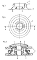
- Weitere Einzelheiten und Vorteile ergeben sich aus der nachfolgenden Beschreibung der zugehörigen Zeichnungen, in denen eine bevorzugte Ausführungsform eines erfindungsgemäß ausgebildeten Druckknopfes dargestellt ist. In den Zeichnungen zeigen:
- Fig. 1
- eine Öse in Ansicht von unten;
- Fig. 2
- dieselbe Öse entlang der Linie II-II in Fig. 1 geschnitten;
- Fig. 3
- eine Kugel entlang der Linie III-III in Fig. 4 geschnitten;
- Fig. 4
- dieselbe Kugel in Draufsicht;
- Fig. 5
- eine Öse und eine Kugel im vernieteten und verrasteten Zustand im Längsschnitt.
- In den Fig. 1 bis 4 sind eine Öse 1 und eine Kugel 2 vor der Montage dargestellt. In der Öse 1 ist als Federelement eine S-Feder 3 so angeordnet, daß die inneren Schenkel der S-Feder 3 in die beiden parallel zueinander angeordneten Schlitze 4 im Innenteil der Öse 1 eingreifen. Die S-Feder 3 ist in ein Federgehäuse 5 eingesetzt, welches auf der Außenseite eine Sicke 6 aufweist, die der Festlegung der S-Feder 3 im Federgehäuse 5 dient. Auf der Innenseite der Öse 1 ist an dem Federgehäuse 5 ein Zentrierkonus 7 angeformt. Durch die Verlegung der Federebene der S-Feder 3 in axialer Richtung auf die Mitte der Öse 1 hin ändert sich die Bauhöhe der Öse 1 gegenüber Ösen ohne Zentrierkonus 7 nicht.
- Wie aus Fig. 5 ersichtlich, wird zur Verbindung mit dem Flächenmaterial 8 ein Nietschaft 9 durch ein Nietloch 10 gesteckt und in der Öse 1 angebördelt. Der Nietschaft 9 stanzt dabei das Flächenmaterial 8 aus, so daß sich dieses an den Rändern nicht kräuseln kann. An den Nietschaft 9 ist einstückig ein Nietflansch 11 angeformt, welcher in den umgebördelten Rändern einer Kappe 12 festgelegt ist.
- Die mit der Öse 1 korrespondierende Kugel 2 weist zwischen einem Kugelflansch 13 und einem Schnappbereich 14 einen Zentrierkegel 15 auf.
- Die Kugel 2 wird in gleicher Weise wie die Öse 1 mittels eines Nietschaftes 16 mit angeformtem Nietflansch 17 mit dem Flächenmaterial 8 verbunden. Hierbei stanzt wiederum der Nietschaft 16 das Flächenmaterial 8 an der Durchdringungsstelle aus und wird anschließend im Nietloch 18 angebördelt.
-
- 1
- Öse
- 2
- Kugel
- 3
- S-Feder
- 4
- Schlitz
- 5
- Federgehäuse
- 6
- Sicke
- 7
- Zentrierkonus
- 8
- Flächenmaterial
- 9
- Nietschaft
- 10
- Nietloch
- 11
- Nietflansch
- 12
- Kappe
- 13
- Kugelflansch
- 14
- Schnappbereich
- 15
- Zentrierkegel
- 16
- Nietschaft
- 17
- Nietflansch
- 18
- Nietloch
Claims (3)
- Druckknopf für Flächenmaterial, bestehend aus einem Oberteil und aus einem Unterteil, die jeweils an zu verbindenden Flächenmaterialien (8) befestigbar und miteinander verrastbar sind, wobei das Oberteil und das Unterteil jeweils aus einem auf das Flächenmaterial (8) einwirkenden Nietschaft (9, 16) mit angeformtem Nietflansch (11, 17) sowie aus einem aus einer Kugel (2) bzw. einer Öse (1) bestehenden Rastteil auf der anderen Seite des Flächenmaterials (8) besteht, wobei der Nietschaft (9, 16) in dem Flächenmaterial (8) vernietet ist, und in der Öse (1) des Unterteils in einem Federgehäuse (5) eine Feder (3) als Federelement angeordnet ist, deren innere Schenke in zwei zueinander parallelen Schlitzen (4) im Innenteil der Öse (1) des Unterteils federnd eingesetzt sind,
dadurch gekennzeichnet, daß auf der Innenseite der Öse (1) an dem Federgehäuse (5) ein Zentrierkonus (7) angeformt und der mittlere Schenkel der Feder (3) in dem Federgehäuse (5) in axialer Richtung auf den Zentrierkonus (7) hin versetzt angeordnet ist, daß das Federgehäuse (5) auf der Außenseite eine Sicke (6) aufweist und daß die Feder (3) in Richtung auf die Kugel (2) bombiert ist. - Druckknopf nach Anspruch 1, dadurch gekennzeichnet, daß an der Kugel (2) zwischen Schnappbereich (14) und Kugelflansch (13) ein Zentrierkegel (15) angeformt ist.
- Druckknopf nach Anspruch 1, dadurch gekennzeichnet, daß die Kugel (2) offen ist und der Nietschaft (16) in einem Nietloch (18) vernietet ist.
Applications Claiming Priority (2)
| Application Number | Priority Date | Filing Date | Title |
|---|---|---|---|
| DE4137418 | 1991-11-14 | ||
| DE4137418A DE4137418C2 (de) | 1991-11-14 | 1991-11-14 | Druckknopf |
Publications (2)
| Publication Number | Publication Date |
|---|---|
| EP0542029A1 EP0542029A1 (de) | 1993-05-19 |
| EP0542029B1 true EP0542029B1 (de) | 1995-08-23 |
Family
ID=6444770
Family Applications (1)
| Application Number | Title | Priority Date | Filing Date |
|---|---|---|---|
| EP92118328A Expired - Lifetime EP0542029B1 (de) | 1991-11-14 | 1992-10-27 | Druckknopf |
Country Status (3)
| Country | Link |
|---|---|
| EP (1) | EP0542029B1 (de) |
| AT (1) | ATE126679T1 (de) |
| DE (2) | DE4137418C2 (de) |
Families Citing this family (2)
| Publication number | Priority date | Publication date | Assignee | Title |
|---|---|---|---|---|
| RU2161898C2 (ru) * | 1999-02-11 | 2001-01-20 | Кузьмин Иван Александрович | Кнопка-пружинка |
| JP5132490B2 (ja) * | 2008-09-04 | 2013-01-30 | Ykk株式会社 | 雄型スナップ |
Family Cites Families (9)
| Publication number | Priority date | Publication date | Assignee | Title |
|---|---|---|---|---|
| US1386306A (en) * | 1919-05-08 | 1921-08-02 | Baum Charles | Snap-fastener |
| US1387114A (en) * | 1920-01-16 | 1921-08-09 | Carr Fastener Co Ltd | Fastener |
| FR1062583A (fr) * | 1952-06-06 | 1954-04-26 | Scovill Manufactring Co | Perfectionnements aux boutons-pression s'ouvrant dans une seule direction |
| GB724609A (en) * | 1952-06-14 | 1955-02-23 | United Carr Fastener Corp | Improvements in and relating to snap fastener members of the stud and socket type |
| US2861317A (en) * | 1955-09-29 | 1958-11-25 | Rau Fastener Company | Ornamental snap fastener assembly |
| JPS5325604Y2 (de) * | 1974-05-21 | 1978-06-30 | ||
| FR2518377A1 (fr) * | 1981-12-18 | 1983-06-24 | Sonofam | Bouton-fermoir |
| DE3514896A1 (de) * | 1985-04-25 | 1986-11-06 | William Prym-Werke GmbH & Co KG, 5190 Stolberg | Druckknopfverbindung |
| DE8915362U1 (de) * | 1989-06-06 | 1990-04-26 | William Prym-Werke GmbH & Co KG, 5190 Stolberg | Druckknopfverbindung |
-
1991
- 1991-11-14 DE DE4137418A patent/DE4137418C2/de not_active Expired - Fee Related
-
1992
- 1992-10-27 EP EP92118328A patent/EP0542029B1/de not_active Expired - Lifetime
- 1992-10-27 AT AT92118328T patent/ATE126679T1/de not_active IP Right Cessation
- 1992-10-27 DE DE59203375T patent/DE59203375D1/de not_active Expired - Fee Related
Also Published As
| Publication number | Publication date |
|---|---|
| DE4137418C2 (de) | 1995-07-06 |
| DE59203375D1 (de) | 1995-09-28 |
| DE4137418A1 (de) | 1993-05-19 |
| ATE126679T1 (de) | 1995-09-15 |
| EP0542029A1 (de) | 1993-05-19 |
Similar Documents
| Publication | Publication Date | Title |
|---|---|---|
| EP3047165B1 (de) | Befestigungskralle | |
| DE3321881A1 (de) | Kupplungsmechanismus, insbesondere fuer kraftfahrzeuge | |
| DE3114011C2 (de) | ||
| EP3158208A1 (de) | Bauteilverbindung | |
| CH451601A (de) | Befestigungsmittel | |
| EP0013377B1 (de) | Ventil | |
| DE4322669C2 (de) | Befestigungseinrichtung | |
| DE1196119B (de) | Topffoermige Abdeckkappe aus Kunststoffmaterial fuer Dosen, insbesondere Aerosoldosen | |
| DE3706807C2 (de) | Druckknopfteil | |
| EP1670993A1 (de) | Deckel einer schachtabdeckung sowie schachtabdeckung | |
| DE2130180A1 (de) | Druckknopfartiger Sicherheitsverschluss | |
| EP0542029A1 (de) | Druckknopf | |
| DE2452766C3 (de) | Flaschenverschluß für Kronenkorkenflaschen | |
| EP0090131B1 (de) | Kunststoffkappe an Halteteilen für Kurzwarenartikel, wie Druckknopfteile | |
| DE2035735A1 (de) | Kunststoff-Druckknopf | |
| DE2058688B2 (de) | Mehrstufiger Membranantrieb zur Steuerung eines Stellglieds, insbesondere eines Ventils | |
| DE202019100668U1 (de) | Zwei elastische Ringkörper aufweisende Drehachsenanordnung für eine Lenkrolle | |
| DE3601962C2 (de) | Patrize eines Druckknopfes oder dergleichen | |
| DE3212154C1 (de) | Abdeckkappe für Schlitzschrauben | |
| AT396398B (de) | Einrichtung zur halterung eines schauglases | |
| DE69104524T2 (de) | Druckvorrichtung für eine Kupplungstellerfeder, insbesondere für Kraftfahrzeuge. | |
| DE2037163A1 (de) | Pfannenglied für Druckknopf | |
| DE2251629C3 (de) | Klemmrollen-Freilaufkupplung | |
| CH386932A (de) | Uhrgehaeuseboden | |
| DE7641068U (de) | KupplungsausrUcklager |
Legal Events
| Date | Code | Title | Description |
|---|---|---|---|
| PUAI | Public reference made under article 153(3) epc to a published international application that has entered the european phase |
Free format text: ORIGINAL CODE: 0009012 |
|
| AK | Designated contracting states |
Kind code of ref document: A1 Designated state(s): AT BE DE FR GB NL |
|
| 17P | Request for examination filed |
Effective date: 19930714 |
|
| 17Q | First examination report despatched |
Effective date: 19940801 |
|
| RAP1 | Party data changed (applicant data changed or rights of an application transferred) |
Owner name: STOCKO VERSCHLUSSTECHNIK GMBH & CO. |
|
| GRAA | (expected) grant |
Free format text: ORIGINAL CODE: 0009210 |
|
| AK | Designated contracting states |
Kind code of ref document: B1 Designated state(s): AT BE DE FR GB NL |
|
| REF | Corresponds to: |
Ref document number: 126679 Country of ref document: AT Date of ref document: 19950915 Kind code of ref document: T |
|
| ET | Fr: translation filed | ||
| GBT | Gb: translation of ep patent filed (gb section 77(6)(a)/1977) |
Effective date: 19950821 |
|
| REF | Corresponds to: |
Ref document number: 59203375 Country of ref document: DE Date of ref document: 19950928 |
|
| PLBE | No opposition filed within time limit |
Free format text: ORIGINAL CODE: 0009261 |
|
| STAA | Information on the status of an ep patent application or granted ep patent |
Free format text: STATUS: NO OPPOSITION FILED WITHIN TIME LIMIT |
|
| REG | Reference to a national code |
Ref country code: GB Ref legal event code: 732E |
|
| 26N | No opposition filed | ||
| NLS | Nl: assignments of ep-patents |
Owner name: STOCKO FASTENERS GMBH |
|
| REG | Reference to a national code |
Ref country code: FR Ref legal event code: TP |
|
| REG | Reference to a national code |
Ref country code: FR Ref legal event code: TP |
|
| NLS | Nl: assignments of ep-patents |
Owner name: YKK CORPORATION |
|
| REG | Reference to a national code |
Ref country code: GB Ref legal event code: IF02 |
|
| PGFP | Annual fee paid to national office [announced via postgrant information from national office to epo] |
Ref country code: DE Payment date: 20071025 Year of fee payment: 16 Ref country code: NL Payment date: 20071015 Year of fee payment: 16 |
|
| PGFP | Annual fee paid to national office [announced via postgrant information from national office to epo] |
Ref country code: AT Payment date: 20071011 Year of fee payment: 16 |
|
| PGFP | Annual fee paid to national office [announced via postgrant information from national office to epo] |
Ref country code: GB Payment date: 20071024 Year of fee payment: 16 Ref country code: FR Payment date: 20071009 Year of fee payment: 16 |
|
| PGFP | Annual fee paid to national office [announced via postgrant information from national office to epo] |
Ref country code: BE Payment date: 20081010 Year of fee payment: 17 |
|
| GBPC | Gb: european patent ceased through non-payment of renewal fee |
Effective date: 20081027 |
|
| NLV4 | Nl: lapsed or anulled due to non-payment of the annual fee |
Effective date: 20090501 |
|
| REG | Reference to a national code |
Ref country code: FR Ref legal event code: ST Effective date: 20090630 |
|
| PG25 | Lapsed in a contracting state [announced via postgrant information from national office to epo] |
Ref country code: NL Free format text: LAPSE BECAUSE OF NON-PAYMENT OF DUE FEES Effective date: 20090501 |
|
| PG25 | Lapsed in a contracting state [announced via postgrant information from national office to epo] |
Ref country code: AT Free format text: LAPSE BECAUSE OF NON-PAYMENT OF DUE FEES Effective date: 20081027 Ref country code: DE Free format text: LAPSE BECAUSE OF NON-PAYMENT OF DUE FEES Effective date: 20090501 |
|
| PG25 | Lapsed in a contracting state [announced via postgrant information from national office to epo] |
Ref country code: FR Free format text: LAPSE BECAUSE OF NON-PAYMENT OF DUE FEES Effective date: 20081031 |
|
| PG25 | Lapsed in a contracting state [announced via postgrant information from national office to epo] |
Ref country code: GB Free format text: LAPSE BECAUSE OF NON-PAYMENT OF DUE FEES Effective date: 20081027 |
|
| BERE | Be: lapsed |
Owner name: *YKK CORP. Effective date: 20091031 |
|
| PG25 | Lapsed in a contracting state [announced via postgrant information from national office to epo] |
Ref country code: BE Free format text: LAPSE BECAUSE OF NON-PAYMENT OF DUE FEES Effective date: 20091031 |