EP0541975B1 - Einzugsgehäuse für Feldhäcksler - Google Patents
Einzugsgehäuse für Feldhäcksler Download PDFInfo
- Publication number
- EP0541975B1 EP0541975B1 EP92117436A EP92117436A EP0541975B1 EP 0541975 B1 EP0541975 B1 EP 0541975B1 EP 92117436 A EP92117436 A EP 92117436A EP 92117436 A EP92117436 A EP 92117436A EP 0541975 B1 EP0541975 B1 EP 0541975B1
- Authority
- EP
- European Patent Office
- Prior art keywords
- draw
- housing
- shaft
- respect
- sliders
- Prior art date
- Legal status (The legal status is an assumption and is not a legal conclusion. Google has not performed a legal analysis and makes no representation as to the accuracy of the status listed.)
- Expired - Lifetime
Links
- 239000004459 forage Substances 0.000 title claims description 3
- 241001124569 Lycaenidae Species 0.000 claims description 2
- 230000008878 coupling Effects 0.000 claims 2
- 238000010168 coupling process Methods 0.000 claims 2
- 238000005859 coupling reaction Methods 0.000 claims 2
- 230000005540 biological transmission Effects 0.000 claims 1
- 239000000463 material Substances 0.000 description 2
- 238000007789 sealing Methods 0.000 description 1
Images
Classifications
-
- A—HUMAN NECESSITIES
- A01—AGRICULTURE; FORESTRY; ANIMAL HUSBANDRY; HUNTING; TRAPPING; FISHING
- A01F—PROCESSING OF HARVESTED PRODUCE; HAY OR STRAW PRESSES; DEVICES FOR STORING AGRICULTURAL OR HORTICULTURAL PRODUCE
- A01F29/00—Cutting apparatus specially adapted for cutting hay, straw or the like
- A01F29/09—Details
- A01F29/10—Feeding devices
Definitions
- the invention relates to intake housing for forage harvesters according to the preamble of claim 1.
- Feeder housings of this type are e.g. B. from DE-OS 21 49 974 known.
- the task was to be solved to cover the open slots in the housing walls with sliders so that no chopped material could come out. Since the movement of the rollers during their height movement was not strictly defined here, the slides had to be fitted with great lateral play in their respective guides. In practice, this led to the fact that on the one hand the slides could easily tilt in the guides and, on the other hand, that the chopped material that had penetrated within the play of the side movements of the slider was compacted in the guides so that after some time the movement of the slides blocked has been.
- both disadvantages can be avoided in that the slides are connected to the shaft of the height-adjustable feed roller in accordance with the characterizing features of claim 1 or claim 2.
- tension-free movement of the slides is possible during the feeding of the feed rollers.
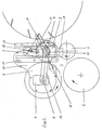
- a feeder housing has two housing walls (1). A front and a rear lower feed roller (2, 3) are mounted in these. Furthermore, slots (4, 5) are provided, through which shafts (6, 7) for a front and a rear upper feed roller (8, 9) pass. Bolts (10) on which the rockers (11) are rotatably mounted are fastened to the housing walls (1). The shaft (7) of the rear upper feed roller (9) is mounted on the free ends (12) of the rockers (11). Coaxial to the shaft (7) on the one side of the feeder housing, a link (13) and on the other side a gear housing (14), which also serves as a link, is mounted so that it can swing.
- the free end of the handlebar (13) and the gear housing (14) are penetrated by the shaft (6) for the front upper feed roller (8).
- the front and rear feed rollers (8, 9) can move upwards against the action of springs, not shown.
- a front guide (15) and a rear guide (16) are firmly attached to the outer surfaces of the housing walls (1) in the area of the slots (5).
- Sliders (17) can slide up and down in them.
- the slides (17) are so snugly fitted in the guides (15, 16) that they cannot tilt when they are moved.
- the slide (17) on one side of the feed housing has an approximately horizontal elongated hole (18) through which the shaft (7) passes.
- the slide (17) on the other side also has a passage for the shaft (7).
- it is additionally articulated to the gear housing (14) by means of a tab (19). This allows the slides (17) to follow vertical movements of the shaft (7) or the gear housing (14) without getting stuck in their guides (15, 16).
- Sliders of the type described can also be provided for sealing the front slots (4).
Landscapes
- Life Sciences & Earth Sciences (AREA)
- Environmental Sciences (AREA)
- Feeding And Watering For Cattle Raising And Animal Husbandry (AREA)
- Orthopedics, Nursing, And Contraception (AREA)
Description
- Die Erfindung bezieht sich auf Einzugsgehäuse für Feldhäcksler nach dem Gattungsbegriff des Anspruches 1.
- Einzugsgehäuse dieser Art sind z. B. aus der DE-OS 21 49 974 bekannt. Hier sollte die Aufgabe gelöst werden, die offenen Schlitze in den Gehäusewänden mit Schiebern so abzudecken, daß kein Häckselgut nach außen treten konnte. Da hier die Bewegung der Walzen bei ihrer Höhenbewegung nicht streng definiert war, mußten die Schieber mit großem seitlichen Spiel in ihre jeweiligen Führungen eingepaßt werden. Das führte in der Praxis dazu, daß zum einen sich die Schieber in den Führungen leicht verkanten konnten und zum anderen, daß das innerhalb des Spieles der Seitenbewegungen des Schiebers eingedrungene Häckselgut in den Führungen so verdichtet wurde, daß nach einiger Zeit die Bewegung der Schieber blockiert wurde.
- Beide Nachteile können erfindungsgemäß dadurch vermieden werden, daß die Schieber entsprechend den kennzeichnenden Merkmalen des Anspruches 1 oder des Anspruches 2 mit der Welle der höhenbeweglichen Einzugswalze verbunden sind. Bei solchen Ausführungen ist eine spannungsfreie Bewegung der Schieber während der Gutzuführung der Einzugswalzen möglich.
- Die Erfindung wird anhand von zwei Abbildungen beispielsweise erläutert.
- Figur 1
- zeigt ein Einzugsgehäuse schematisch in Seitenansicht
- Figur 2
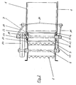
- zeigt den gleichen Gegenstand in Draufsicht
- Ein Einzugsgehäuse hat zwei Gehäusewände (1). In diesen sind eine vordere und eine hintere untere Einzugswalze (2, 3) gelagert. Desweiteren sind Schlitze (4, 5) vorgesehen, durch die Wellen (6, 7) für eine vordere und eine hintere obere Einzugswalze (8, 9) durchtreten. An den Gehäusewänden (1) sind Bolzen (10) befestigt, auf denen Schwingen (11) drehbar gelagert sind. An den freien Enden (12) der Schwingen (11) ist die Welle (7) der hinteren oberen Einzugswalze (9) gelagert. Koaxial zu der Welle (7) sind auf der einen Seite des Einzugsgehäuses ein Lenker (13) und auf der anderen Seite ein Getriebegehäuse (14), das gleichzeitig als Lenker dient, schwingbar gelagert. Das freie Ende des Lenkers (13) und das Getriebegehäuse (14) werden von der Welle (6) für die vordere obere Einzugswalze (8) durchsetzt. Die vordere und die hintere Einzugswalze (8, 9) können sich entgegen der Wirkung nicht dargestellter Federn nach oben bewegen. An den Außenflächen der Gehäusewände (1) sind im Bereich der Schlitze (5) eine vordere Führung (15) und eine hintere Führung (16) fest angebracht. In ihnen können Schieber (17) nach oben und unten gleiten. Die Schieber (17) sind in die Führungen (15, 16) so satt eingepaßt, daß sie sich beim Verschieben nicht verkanten können. Der Schieber (17) auf der einen Seite des Einzugsgehäuses hat ein etwa waagrecht liegendes Langloch (18), das von der Welle (7) durchsetzt wird. Der Schieber (17) auf der anderen Seite hat ebenfalls einen Durchlaß für die Welle (7). Er ist aber zusätzlich noch mittels einer Lasche (19) mit dem Getriebegehäuse (14) gelenkig verbunden. Dadurch können die Schieber (17) Höhenbewegungen der Welle (7) bzw. des Getriebegehäuses (14) folgen, ohne sich in ihren Führungen (15, 16) zu verklemmen.
- Schieber der beschriebenen Art können sinngemäß auch zur Abdichtung der vorderen Schlitze (4) vorgesehen werden.
Claims (2)
- Einzugsgehäuse für Feldhäcksler, mit höhenbeweglichen Einzugswalzen (8, 9), von denen mindestens eine an Lenkern (11), die an dem Einzugsgehäuse drehbar befestigt sind, kreisbogenförmig schwingbar gelagert ist, und mit Schlitzen (4, 5) in den Gehäusewänden (1), die von den Wellen (6, 7) der Einzugswalzen (8, 9) durchsetzt werden, sowie mit ebenfalls höhenbeweglichen, durch Führungen (15, 16) gegen Querbewegung gehaltenen Schiebern (17), die die Schlitze (5) in den Gehäusewänden (1) abdecken, dadurch gekennzeichnet, daß die Schieber (17) mittels einer Lasche (19) oder dergleichen Koppelelement mit einem, mit der Welle (7) der Einzugswalze (9) höhenbeweglichen Bauteil, z., B. einem Getriebegehäuse (14), derart gelenkig verbunden sind, daß sich die Schieber (17) synchron zu der Welle (7) nach oben oder unten bewegen.
- Einzugsgehäuse nach Anspruch 1, dadurch gekennzeichnet, daß als Koppelelement die Welle (7) der Einzugswalze (9) oder ein auf der Welle (7) angeordnetes Bauelement, z. B. Nabe, dient, die an den Längsseiten eines im Schieber (17) etwa waagrecht verlaufenden Langloches (18) zur Anlage kommt.
Applications Claiming Priority (2)
| Application Number | Priority Date | Filing Date | Title |
|---|---|---|---|
| DE4136948 | 1991-11-11 | ||
| DE4136948A DE4136948A1 (de) | 1991-11-11 | 1991-11-11 | Einzugsgehaeuse fuer feldhaecksler |
Publications (2)
| Publication Number | Publication Date |
|---|---|
| EP0541975A1 EP0541975A1 (de) | 1993-05-19 |
| EP0541975B1 true EP0541975B1 (de) | 1997-01-08 |
Family
ID=6444463
Family Applications (1)
| Application Number | Title | Priority Date | Filing Date |
|---|---|---|---|
| EP92117436A Expired - Lifetime EP0541975B1 (de) | 1991-11-11 | 1992-10-13 | Einzugsgehäuse für Feldhäcksler |
Country Status (2)
| Country | Link |
|---|---|
| EP (1) | EP0541975B1 (de) |
| DE (2) | DE4136948A1 (de) |
Cited By (3)
| Publication number | Priority date | Publication date | Assignee | Title |
|---|---|---|---|---|
| WO2011042802A2 (en) | 2009-10-09 | 2011-04-14 | Agco Gmbh | Compression roll housing |
| WO2019211512A1 (en) | 2018-05-04 | 2019-11-07 | Oy El-Ho Ab | Arrangement on a harvester for straw -like crop |
| EP4011191A1 (de) | 2020-12-09 | 2022-06-15 | AGCO International GmbH | Kompressionswalzengehäuse |
Families Citing this family (7)
| Publication number | Priority date | Publication date | Assignee | Title |
|---|---|---|---|---|
| GB2323512A (en) * | 1997-03-27 | 1998-09-30 | Ford New Holland Nv | Forage harvester |
| DE10021663A1 (de) * | 2000-05-04 | 2001-11-15 | Krone Bernhard Gmbh Maschf | Erntemaschine, insbesondere selbstfahrender Feldhäcksler |
| DE10235096A1 (de) * | 2002-07-31 | 2004-02-12 | Claas Saulgau Gmbh | Anlenkung der beweglichen Presswalze vor einer Messertrommel eines Häckslergebläses |
| GB201603728D0 (en) | 2016-03-03 | 2016-04-20 | Agco Int Gmbh | Compression roll housing |
| DE102016107360A1 (de) * | 2016-04-20 | 2017-10-26 | Claas Saulgau Gmbh | Einzugvorrichtung für einen Feldhäcksler |
| DE102016118561B4 (de) * | 2016-09-29 | 2024-01-18 | Claas Saulgau Gmbh | Einzugswerk |
| DE102017123024A1 (de) * | 2017-10-04 | 2019-04-04 | Claas Saulgau Gmbh | Einzugswerk |
Family Cites Families (2)
| Publication number | Priority date | Publication date | Assignee | Title |
|---|---|---|---|---|
| DE2149974A1 (de) * | 1971-10-07 | 1973-04-12 | Georueder Eberhardt | Haecksler |
| US3913303A (en) * | 1974-03-04 | 1975-10-21 | Avco Corp | Feed roll construction for forage harvester |
-
1991
- 1991-11-11 DE DE4136948A patent/DE4136948A1/de not_active Withdrawn
-
1992
- 1992-10-13 DE DE59207844T patent/DE59207844D1/de not_active Expired - Fee Related
- 1992-10-13 EP EP92117436A patent/EP0541975B1/de not_active Expired - Lifetime
Cited By (3)
| Publication number | Priority date | Publication date | Assignee | Title |
|---|---|---|---|---|
| WO2011042802A2 (en) | 2009-10-09 | 2011-04-14 | Agco Gmbh | Compression roll housing |
| WO2019211512A1 (en) | 2018-05-04 | 2019-11-07 | Oy El-Ho Ab | Arrangement on a harvester for straw -like crop |
| EP4011191A1 (de) | 2020-12-09 | 2022-06-15 | AGCO International GmbH | Kompressionswalzengehäuse |
Also Published As
| Publication number | Publication date |
|---|---|
| DE59207844D1 (de) | 1997-02-20 |
| EP0541975A1 (de) | 1993-05-19 |
| DE4136948A1 (de) | 1993-05-13 |
Similar Documents
| Publication | Publication Date | Title |
|---|---|---|
| DE2948664C2 (de) | Landmaschine | |
| DE2910139A1 (de) | Selbstfahrender maehdrescher mit automatischer maehtisch-hoeheneinstellung | |
| EP0541975B1 (de) | Einzugsgehäuse für Feldhäcksler | |
| DE4015894A1 (de) | Zuckerrohr-vollerntemaschine | |
| EP1062860B1 (de) | Vorrichtung für Erntefahrzeuge, insbesondere für landwirtschaftliche Aufsammelballenpressen | |
| DE2625754C2 (de) | Kreiselegge | |
| EP1095555B1 (de) | Heuwerbungsmaschine | |
| DE3830908C2 (de) | Selbstfahrener Mähdrescher mit zweigeteiltem Schneidwerk | |
| DE69613191T2 (de) | Heuwerbungsmaschine mit mindestens einem Rotor zum Schwaden | |
| EP1133911B1 (de) | Vorrichtung zum Pflücken der Fruchtstände stängeliger Erntegüter | |
| DE3628605A1 (de) | Heuwerbungsmaschine | |
| DE3522699C2 (de) | Selbstfahrende Erntemaschine | |
| DE69209361T2 (de) | Verbesserter Pflanzenschwader | |
| EP1685755A1 (de) | Selbstfahrende landwirtschaftliche Erntemaschine | |
| DE2345494A1 (de) | Sammelblech-anordnung bei einem kolbenpflueck-vorsatzgeraet | |
| DE3546479C2 (de) | ||
| DE3033299C2 (de) | Antrieb für eine Schneidvorrichtung | |
| DE3004969C2 (de) | ||
| DE2821235C2 (de) | Türzarge | |
| EP0400327A1 (de) | Mähdrescher | |
| DE3784107T2 (de) | Maehmaschine. | |
| DE1482804C (de) | Uberkopf Trommelwender | |
| DE2544445B1 (de) | Fadenkreuzvorrichtung fuer schaermaschinen | |
| DD235013A1 (de) | Einzugsfoerderkanal fuer maehdrescher | |
| DE69917571T2 (de) | Heuwerbungsmaschine |
Legal Events
| Date | Code | Title | Description |
|---|---|---|---|
| PUAI | Public reference made under article 153(3) epc to a published international application that has entered the european phase |
Free format text: ORIGINAL CODE: 0009012 |
|
| AK | Designated contracting states |
Kind code of ref document: A1 Designated state(s): DE FR GB IT |
|
| 17P | Request for examination filed |
Effective date: 19931013 |
|
| 17Q | First examination report despatched |
Effective date: 19950403 |
|
| GRAG | Despatch of communication of intention to grant |
Free format text: ORIGINAL CODE: EPIDOS AGRA |
|
| GRAH | Despatch of communication of intention to grant a patent |
Free format text: ORIGINAL CODE: EPIDOS IGRA |
|
| GRAH | Despatch of communication of intention to grant a patent |
Free format text: ORIGINAL CODE: EPIDOS IGRA |
|
| GRAA | (expected) grant |
Free format text: ORIGINAL CODE: 0009210 |
|
| AK | Designated contracting states |
Kind code of ref document: B1 Designated state(s): DE FR GB IT |
|
| ITF | It: translation for a ep patent filed | ||
| REF | Corresponds to: |
Ref document number: 59207844 Country of ref document: DE Date of ref document: 19970220 |
|
| GBT | Gb: translation of ep patent filed (gb section 77(6)(a)/1977) |
Effective date: 19970219 |
|
| ET | Fr: translation filed | ||
| PLBE | No opposition filed within time limit |
Free format text: ORIGINAL CODE: 0009261 |
|
| STAA | Information on the status of an ep patent application or granted ep patent |
Free format text: STATUS: NO OPPOSITION FILED WITHIN TIME LIMIT |
|
| 26N | No opposition filed | ||
| REG | Reference to a national code |
Ref country code: FR Ref legal event code: ST |
|
| PGFP | Annual fee paid to national office [announced via postgrant information from national office to epo] |
Ref country code: GB Payment date: 19990927 Year of fee payment: 8 |
|
| PGFP | Annual fee paid to national office [announced via postgrant information from national office to epo] |
Ref country code: DE Payment date: 19991019 Year of fee payment: 8 |
|
| PGFP | Annual fee paid to national office [announced via postgrant information from national office to epo] |
Ref country code: FR Payment date: 19991022 Year of fee payment: 8 |
|
| REG | Reference to a national code |
Ref country code: FR Ref legal event code: RN |
|
| REG | Reference to a national code |
Ref country code: FR Ref legal event code: FC |
|
| PG25 | Lapsed in a contracting state [announced via postgrant information from national office to epo] |
Ref country code: GB Free format text: LAPSE BECAUSE OF NON-PAYMENT OF DUE FEES Effective date: 20001013 |
|
| GBPC | Gb: european patent ceased through non-payment of renewal fee |
Effective date: 20001013 |
|
| PG25 | Lapsed in a contracting state [announced via postgrant information from national office to epo] |
Ref country code: FR Free format text: LAPSE BECAUSE OF NON-PAYMENT OF DUE FEES Effective date: 20010629 |
|
| PG25 | Lapsed in a contracting state [announced via postgrant information from national office to epo] |
Ref country code: DE Free format text: LAPSE BECAUSE OF NON-PAYMENT OF DUE FEES Effective date: 20010703 |
|
| REG | Reference to a national code |
Ref country code: FR Ref legal event code: ST |
|
| PG25 | Lapsed in a contracting state [announced via postgrant information from national office to epo] |
Ref country code: IT Free format text: LAPSE BECAUSE OF NON-PAYMENT OF DUE FEES;WARNING: LAPSES OF ITALIAN PATENTS WITH EFFECTIVE DATE BEFORE 2007 MAY HAVE OCCURRED AT ANY TIME BEFORE 2007. THE CORRECT EFFECTIVE DATE MAY BE DIFFERENT FROM THE ONE RECORDED. Effective date: 20051013 |