EP0540110A1 - Flexible roll-up door with enhanced thermal insulation - Google Patents
Flexible roll-up door with enhanced thermal insulation Download PDFInfo
- Publication number
- EP0540110A1 EP0540110A1 EP92203296A EP92203296A EP0540110A1 EP 0540110 A1 EP0540110 A1 EP 0540110A1 EP 92203296 A EP92203296 A EP 92203296A EP 92203296 A EP92203296 A EP 92203296A EP 0540110 A1 EP0540110 A1 EP 0540110A1
- Authority
- EP
- European Patent Office
- Prior art keywords
- curtain
- wall
- upright
- vertical
- door according
- Prior art date
- Legal status (The legal status is an assumption and is not a legal conclusion. Google has not performed a legal analysis and makes no representation as to the accuracy of the status listed.)
- Granted
Links
Images


Classifications
-
- E—FIXED CONSTRUCTIONS
- E06—DOORS, WINDOWS, SHUTTERS, OR ROLLER BLINDS IN GENERAL; LADDERS
- E06B—FIXED OR MOVABLE CLOSURES FOR OPENINGS IN BUILDINGS, VEHICLES, FENCES OR LIKE ENCLOSURES IN GENERAL, e.g. DOORS, WINDOWS, BLINDS, GATES
- E06B9/00—Screening or protective devices for wall or similar openings, with or without operating or securing mechanisms; Closures of similar construction
- E06B9/02—Shutters, movable grilles, or other safety closing devices, e.g. against burglary
- E06B9/06—Shutters, movable grilles, or other safety closing devices, e.g. against burglary collapsible or foldable, e.g. of the bellows or lazy-tongs type
- E06B9/0692—Shutters, movable grilles, or other safety closing devices, e.g. against burglary collapsible or foldable, e.g. of the bellows or lazy-tongs type comprising flexible sheets as closing screen
-
- E—FIXED CONSTRUCTIONS
- E06—DOORS, WINDOWS, SHUTTERS, OR ROLLER BLINDS IN GENERAL; LADDERS
- E06B—FIXED OR MOVABLE CLOSURES FOR OPENINGS IN BUILDINGS, VEHICLES, FENCES OR LIKE ENCLOSURES IN GENERAL, e.g. DOORS, WINDOWS, BLINDS, GATES
- E06B9/00—Screening or protective devices for wall or similar openings, with or without operating or securing mechanisms; Closures of similar construction
- E06B9/02—Shutters, movable grilles, or other safety closing devices, e.g. against burglary
- E06B9/06—Shutters, movable grilles, or other safety closing devices, e.g. against burglary collapsible or foldable, e.g. of the bellows or lazy-tongs type
- E06B9/0607—Shutters, movable grilles, or other safety closing devices, e.g. against burglary collapsible or foldable, e.g. of the bellows or lazy-tongs type comprising a plurality of similar rigid closing elements movable to a storage position
- E06B9/0646—Shutters, movable grilles, or other safety closing devices, e.g. against burglary collapsible or foldable, e.g. of the bellows or lazy-tongs type comprising a plurality of similar rigid closing elements movable to a storage position characterised by the relative arrangement of the closing elements in the stored position
- E06B9/0669—Shutters, movable grilles, or other safety closing devices, e.g. against burglary collapsible or foldable, e.g. of the bellows or lazy-tongs type comprising a plurality of similar rigid closing elements movable to a storage position characterised by the relative arrangement of the closing elements in the stored position stored in a zig-zag arrangement
-
- E—FIXED CONSTRUCTIONS
- E06—DOORS, WINDOWS, SHUTTERS, OR ROLLER BLINDS IN GENERAL; LADDERS
- E06B—FIXED OR MOVABLE CLOSURES FOR OPENINGS IN BUILDINGS, VEHICLES, FENCES OR LIKE ENCLOSURES IN GENERAL, e.g. DOORS, WINDOWS, BLINDS, GATES
- E06B9/00—Screening or protective devices for wall or similar openings, with or without operating or securing mechanisms; Closures of similar construction
- E06B9/56—Operating, guiding or securing devices or arrangements for roll-type closures; Spring drums; Tape drums; Counterweighting arrangements therefor
- E06B9/58—Guiding devices
- E06B2009/586—Guiding devices with heating to prevent frost or condensate
Definitions
- the present invention relates to a liftable curtain door with reinforced thermal insulation, intended to equip a bay formed in a partition wall between two volumes of air at different temperatures.
- a liftable curtain door with reinforced thermal insulation intended to equip a bay formed in a partition wall between two volumes of air at different temperatures.
- such a door can be intended to equip cold stores.
- Such liftable curtain doors generally have two lateral uprights, usually metallic, provided with slides in which lateral parts of the liftable curtain slide.
- the object of the present invention is to limit the heat losses due to these metal uprights.
- the subject of the present invention is a liftable curtain door, intended to close off a bay in a wall between two volumes of air at different temperatures, said door comprising two vertical lateral uprights which each form a slide delimited by two vertical edges; said door comprising a lifting curtain which has lateral parts sliding in said rails, characterized in that each lateral upright comprises two vertical metal profiles which each form a vertical edge of the rail and which are further separated from each other by a vertical slot extending over substantially the entire height of the upright, at least one of said vertical profiles being closer to the wall and in sealed contact with the wall and in substantially sealed contact with the curtain over the entire height of the curtain, at least when said curtain is lowered.
- the curtain may be in substantially permanent sealed contact, over its entire height, with said vertical profile which is in sealed contact with the wall and / or the door may further comprise applicator members, for applying the curtain against said curtain in substantially sealed contact vertical profile which is in tight contact with the wall, when said curtain is lowered.
- each lateral upright comprises at least one horizontal metal plate, and said plate is constituted by two metal plates which are not in direct contact with each other, one of said plates constituting one of said organs of connection and being welded to the entire profile of one of said vertical profiles and to a short length of the profile of the other of said vertical profiles, the other of said plates being welded to substantially the entire remaining length of the profile of said other of said profiles vertical.
- said metal plates are cut by substantially following the profile of the vertical metal profiles, so as to limit the heat exchanges and / or said plate is covered with a plate made of thermal insulating material.
- each upright has a substantially U-shaped section with a base substantially perpendicular to the wall and two branches extending from the base towards the opening to be closed, the base and the branches of the U having inside a lining made of thermal insulating material in which the said lateral parts of the curtain slide, one of the branches of the U is in tight contact with the wall and comprises said vertical slot which separates said two sections, so that one of said sections constitutes a part of said branch which is distant from the base of the U, this section is in substantially sealed contact with the curtain, over the entire height of the curtain , at least when said curtain is lowered, and said uprights are arranged on one side of the wall which is in contact with a volume of air at a temperature below 0 ° C, while the other side of the wall is in contact with an air volume at a temperature above 0 ° C.
- said lining is provided with heating means for heating said lining.
- each jamb has a substantially U-shaped section with a base substantially perpendicular to the wall and two branches extending from the base towards the opening to be closed, the base and the branches of the U having internally a lining made of thermal insulating material in which the said lateral parts of the curtain slide, one of the branches of the U is in tight contact with the wall and comprises said vertical slot which separates said two sections, so that one of said sections constitutes a part of said branch which is distant from the base of the U, and this section is in substantially sealed contact with the curtain, over the entire height of the curtain, at least when said curtain is lowered, and wherein said lining is provided with heating means for heating said lining and said uprights are arranged on one side of the wall which is in contact with an air volume at a temperature below 0 ° C, while the other side of the wall is in contact with an air volume at a temperature above 0 ° C, and said insulating plate which covers said
- each upright has a substantially U-shaped section, with a base substantially perpendicular to the wall and two branches extending from the base away from the bay to be closed, said slot is formed. in the base and constitutes said slide, the interior of the U-shaped section thus being accessible so that it can be cleaned.
- each upright has a substantially V-shaped section, with a top close to the bay and two divergent branches which extend away from the bay from the top, said slot is formed at the Mountain peak of the V and constitutes said slide, the interior of the V section being thus accessible so that it can be cleaned.
- each upright has a substantially U-shaped section, with a base substantially parallel to the wall and two branches which extend away from the base, one of said branches being closer to the bay, said slot is formed in said branch closer to the bay and constitutes said slide, the interior of the U-section being thus accessible, so that it can be cleaned.
- the slot of each lateral upright is advantageously bordered by lips substantially parallel to the curtain or rounded, and the branches of the U-shaped section of the uprights can have a horizontal length narrowed at the bottom.
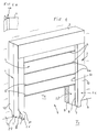
- the present invention relates to a door intended to close a bay 5 in a wall 9, separating two volumes of temperature air different T1, T2.
- T1 can be + 20 ° C and T2 -40 ° C.
- the door comprises an insulating curtain 4 which can be raised by winding and two generally metal lateral uprights 1, 2, each provided with a slide 8 for guiding the curtain 4.
- the lateral uprights 1, 2 are joined at their upper ends by a cross member 3 which contains the mechanism for actuating the curtain, but this characteristic could be omitted without departing from the scope of the present invention.
- the door shown in Figure 1 is of the type commonly called "handling door", that is to say a quick opening door intended to open to the passage of a handling machine and to close after the passage of said device.
- Each lateral upright 1, 2 has a front wall 7, which is here substantially perpendicular to the curtain 4, and which is provided with a longitudinal slot 8 forming said slide.
- the wall 7 does not necessarily have to be perpendicular to the curtain 4: it suffices that the wall 7 is locally not parallel to the curtain 4 in the vicinity of the slot 8.
- the lateral uprights 1 , 2 have a U-shaped section, and each have two walls 10 which extend a certain distance from said wall 7, towards the outside of the opening 5.
- the lateral uprights can have a section equivalent to a U-shaped section, for example an H or V section.
- Each lateral upright 1, 2 consists of two metal sections 26, 27 with an L-shaped section, which are separated by the slot 8. The section 27 of each lateral upright is in tight contact against the wall 9, so as to minimize the air passages through the opening 5.
- the curtain 4 has lateral parts which slide in the slots 8 of the uprights 1 and 2.
- the curtain 4 is flexible and can be lifted up by winding and comprises horizontal reinforcing bars 6 having axial ends 6a which slide in the slots 8 and the curtain has lateral edges 4a which also slide in the slots 8.
- the curtain 4 may possibly not include reinforcing bars 6.
- the side parts of the curtain which slide in the slots 8 may be adapted to disengage from said slots 8 during a violent impact on the curtain 4, so as to prevent damage to said curtain.
- the lateral edge 4a of the curtain is provided with two sheets of elastic flexible material, fixed to the curtain 4 and extending in V towards the outside of the curtain.
- the divergent branches of the V rests elastically on the front wall 7, each on one side of the slot 8, providing an excellent seal.
- the flexible V-shaped sheets could be replaced by an advantageously hollow bead, forming the lateral edge of the curtain 4.
- the door according to the invention can be actuated by mechanical or electromechanical means well known in the state of the art.
- the curtain 4 can be raised in various ways and be produced in various ways without departing from the scope of the present invention, provided that it has lateral parts sliding in the slots 8.
- Figures 2 to 6 give some non-limiting examples which explain some ways to lift the curtain.
- the curtain 4 can be flexible and wind on a horizontal axis 11 in the upper part of the door.
- the curtain 4 has lateral edges 4a, thickened or not, which slide in the slots 8 of the lateral uprights 1 and 2.
- the curtain 4 could also include horizontal reinforcing bars, the ends of which slide or not in the slots 8.
- the curtain 4 can be folded in accordion.
- the curtain 4 consists of rigid panels 14 which are articulated on horizontal reinforcing bars 6, one of two of which slides in the slots 8 of the uprights 1, 2.
- the door further comprises vertical straps 12, attached to the lowest reinforcing bar 6b, and adapted to be wound on a horizontal axis (not shown) in the upper part of the door.
- the highest reinforcing bar 6c (not visible in FIG. 3) is fixed, so as not to fall when the curtain 4 is lowered into the closed position.
- the winding of the straps 12 causes the lower bar 6b to rise, which brings with it the other reinforcing bars 6 which slide in the slots 8, by folding the curtain 4 in accordion.
- the rigid panels 14 can be panels separated from each other, articulated on the bars 6, or even be formed by a single flexible canvas or a sheet of flexible material common to the entire curtain 4 and stretched by spacers between the bars 6 .
- the curtain 4 is constituted by a flexible wall provided with horizontal reinforcing bars 6, one in two of which slides in the slots 8 of the uprights 1, 2.
- the lowest bar 6b is linked to straps 12 which are wound on an axis 13 in the upper part of the door.
- the winding of the straps 12 on the axis 13 causes the lower bar 6b to rise, which brings with it the other reinforcing bars 6 which slide in the slots 8, by folding the curtain 4 in accordion.
- the upper part 4b of the curtain is of course fixed, so as not to fall when the curtain 4 is lowered into the closed position. It will be noted that in this example, it would possibly be possible for all the reinforcement bars 6 to slide in the slots 8.
- the lateral edge 4a of the curtain is at a very small distance from the front wall 7 of the profile 27 close to the wall 9, so that the lateral edge 4a is substantially in sealed contact with the profile 27, at least when the curtain is lowered, in order to minimize the air passages through the opening 5.
- the edge 4a of the curtain can comprise a strip of flexible material, such as a rubber strip possibly slotted in the direction of the release, which bears elastically against the front wall 10 of the profile 27. Examples of flexible curtain strips are given in document EP-A-0 194 494 of the applicant and in the corresponding American patent US -A-4 934 437.
- the curtain 4 can still be produced differently. For example, as shown in Figure 5, it can be lifted without folding accordion or winding, but by simple translation upwards, possibly with a certain inclination relative to the vertical. In FIG. 5, the uprights 1, 2 are thus extended by inclined slides 15, 16. The curtain 4 can then be flexible, reinforced or not by horizontal reinforcing bars, or even made up of rigid articulated panels, etc. If the guide rails 15, 16 are in alignment with the lateral uprights 1, 2, the curtain 4 could even consist of a single rigid panel.
- the curtain 4 can be made up of independent rigid panels 17, which are stacked in the upper part of the door when the curtain 4 is raised, as shown in FIG. 6.
- FIG 7 there is shown the amount 1 of Figure 1, with a curtain 4 with thickened edge 4a which slides in the slot 8, separating two volumes of air at different temperatures T1 and T2. Because there is an opening 34 between the branches of the U, which separates the two sections 26, 27, the only possible heat exchange between the two air masses at T1 and T2 is by conduction through the section 27 in L, without any fin effect since one side of the profile 27 is in contact with the wall 9 and with the air mass at T2 while the other side is in contact with the air mass at T1: the heat exchanges are therefore made through a much more limited surface than in the prior art, where the upright generally has a rear wall in place of the opening 34 so that the upright forms a fin for dissipating heat .
- the U-shaped section of the upright in Figures 1 and 7 makes it easy to clean the upright substantially entirely, which is very important in all places where strict hygiene must be maintained, for example cold stores for food, pharmaceutical laboratories, etc.
- the front wall 7 which is close to the bay 5 and therefore which is likely to come into contact with objects or people crossing the bay 5, can be cleaned on both sides: a first side 7a directed towards the curtain 4, and on a second side 7b opposite the curtain 4, because these two sides are easily accessible.
- the side 7b is accessible through the opening 34 of the upright, between the two side walls 10.
- the U-shaped section of the uprights like other profiled sections, gives them good mechanical resistance.
- the walls 10 of each upright may have a notch 35 in the lower part, to facilitate cleaning with a lance.
- the uprights 1 and 2 can also have other sections than a U-shaped section having planar walls.
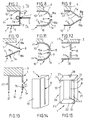
- Figure 8 shows a variant of the upright of Figure 7, still having a substantially U-shaped section, but with a rounded front wall 7.
- the wall 7 comprises two lips 18a, 18b which laterally delimit the slot 8. These lips 18a, 18b extend over the height of the slot 8, and extend over a short horizontal distance, parallel to the curtain 4, towards said curtain or away from said curtain.
- Such lips can be advantageous in certain cases, to avoid damaging by localized friction the lateral parts which slide in the slots 8 of the lateral uprights. Their width is small, so that they can be easily cleaned.
- FIG. 9 represents another variant of the section of FIG. 8, but with a wall 7 with a V section.
- FIG. 10 represents another variant, in which the lateral uprights only have a V-shaped wall 7.
- FIG. 11 represents a variant of FIG. 8, in which the flat lips 18a, 18b are replaced by rounded parts 19a, 19b.
- the longitudinal lateral edges of the slot 8 can be provided with a protective coating, for example anti-friction, without departing from the scope of the present invention.
- the lateral upright has an H section in which the wall 7 having the slot 8 extends between two wing walls 20 parallel to the curtain, the wing walls 20 extending at both towards the curtain 4 and towards the outside of the opening 5 from the front wall 7.
- Such an upright with an H-section can possibly be formed by two U-shaped section profiles assembled, or by four assembled angles 30, 31, 32, 33, as shown in FIG. 12a.
- the section of the lateral uprights 1, 2 has a U shape having a base 22 and two branches 21, but the slot 8 is formed in a wall 7 which represents one of the branches 21 of the U.
- the sections of the uprights of FIGS. 7 to 13 can advantageously be used even when the door separates two air masses of identical or little different temperatures, but in places where strict hygiene must be maintained. In this case, it is not necessarily necessary to have a tight contact between the upright and the wall around the opening, and between the curtain and the upright, unless the door must prevent air passages to other reasons (sterile or dust-free room, overpressure room, ...)
- the two angles 32, 33 closer to the curtain may optionally be made of plastic, and the other two angles 30, 31 of steel. This favors the sliding of the curtain, and we limit the damage caused by shocks from handling equipment on the uprights, while limiting heat exchange.
- the uprights 1, 2 can also be produced in a single piece, as shown in FIG. 14, in which case the slot 8 is cut in the front wall 7.
- the slot 8 can possibly open out in the upper part of the wall 7 for example if the curtain 4 is raised by winding, but said slot 8 may also not open into the upper part of the wall 7, as shown in Figure 14, for example in the case where the curtain 4 is raised by folding accordion.
- the amount has two walls 10 parallel to the curtain 4: these walls 10 may optionally be connected to each other by spacers to strengthen the amount.
- the lateral uprights 1, 2 can also be produced in two assembled pieces 26, 27, which each delimit a longitudinal edge of the slot 8.
- the two pieces 26, 27 are angle sections with a cross section L and are assembled by horizontal spacer plates or plates 22, 23, possibly associated with corner reinforcements 24.
- the upper plate 23 may optionally include a cutout 28 in correspondence with the slot 8 to allow said slot 8 to open into upper part of the upright.
- the plates 22, 23 can be welded, riveted, bolted, or fixed by any other means.
- the plates 22, 23 can optionally be produced in two parts, as in FIG. 18.
- FIG. 16 represents another variant of the invention, in which the curtain is raised by accordion folding as in FIGS. 3 and 4, but where the lateral uprights have a U shape with the branches of the U facing towards the inside the bay 5.
- One of the branches of the U is in tight contact against the wall 9, and as can be seen in FIGS. 17 and 18, this branch of the U has over its entire height a vertical slot 36 which separates the upright into two sections 26, 27, as seen previously.
- an applicator member 38 such as that shown in FIG. 18a, which has the shape of an elongated plastic body, mounted by an elastic articulation 39 on the profile 26.
- an applicator member 38 is described in more detail in document EP-A-0 416 961 of the applicant or in the corresponding patent US-A-5 095 964.
- the edge 4a of the curtain could possibly include flexible bands rubbing on the base of the U-shaped profile, such as those shown in FIG. 19, and described in document EP-A-0 194 194 of the applicant and in the corresponding American patent US -A-4 934 437.
- the sections 26 and 27 comprise, in the upper part and in the lower part, plates made up of two plates which are not in direct contact with each other.
- Figure 18 shows the lower plate 22, consisting of two plates 22a, 22b which lie on the ground and are separated from each other by a slot 22c.
- the plate 22a is welded to the profile 27 over the entire profile of this profile and to the profile 26 over a short length of the profile of the profile 26.
- the plate 22b is welded to the remaining length of the profile of the profile 26.
- the plates 22a and 22b are cut substantially following the profile of profiles 26 and 27, so as to have minimum dimensions of said plates to limit heat exchange.
- the plate 22a constitutes a connecting member between the two profiles 26 and 27. Thanks to the slot 22c and the small width of the plate 22a, said plate constitutes a very limited thermal bridge between the profiles 26 and 27.
- the plate 22b serves to stiffen the profile 26 and improve its seat on the ground.
- Figures 19 and 20 show a variant of the amount of Figure 18, more especially intended for cases where said amount is located on one side of the wall 9 which is at a temperature T2 lower than 0 ° C, while the other side of wall 9 is at a temperature T1 greater than 0 ° C.
- the interior of the U-shaped section of the upright is coated with an insulating lining 40, which aims in particular to avoid the formation of frost.
- the lining 40 can advantageously be provided with heating means, such as for example resistive electrical wires 41.
- heating means such as for example resistive electrical wires 41.
- the lateral edges 4a of the curtain are provided with flexible insulating bands 42, for example of rubber, which rub on the base of the U-section of the upright: such bands insulators are described in more detail in document EP-A-0 194 194 of the applicant and in the corresponding American patent US-A-4,934,437.
- the amount may not have an applicator member 38, the curtain 4 being in leaktight contact with the profile 27 by means of the flexible strips 42 and the insulating lining 40.
- the lower plate 22 is covered with an insulating plate 43, having a slope towards the outside of the U, that is to say towards the opening 5, represented by the arrows 44 in FIG. 19 in order to evacuate condensation or defrost water, or water from cleaning inside the upright, outside the upright.
- the plate 43 includes heating means 45, for example electric heating resistors embedded in the plate 43 if the latter is made of plastic: this prevents the formation of frost on the plate 43.
Abstract
Description
La présente invention concerne une porte à rideau relevable à isolation thermique renforcée, destinée à équiper une baie ménagée dans un mur de séparation entre deux volumes d'air à température différentes. Par exemple, une telle porte peut être destinée à équiper des entrepôts frigorifiques.The present invention relates to a liftable curtain door with reinforced thermal insulation, intended to equip a bay formed in a partition wall between two volumes of air at different temperatures. For example, such a door can be intended to equip cold stores.
De telles portes à rideau relevable comportent généralement deux montants latéraux, habituellement métalliques, dotés de glissières dans lesquelles coulissent des parties latérales du rideau relevable.Such liftable curtain doors generally have two lateral uprights, usually metallic, provided with slides in which lateral parts of the liftable curtain slide.
La présente invention a pour but de limiter les pertes thermiques dues à ces montants métalliques.The object of the present invention is to limit the heat losses due to these metal uprights.
Ainsi, la présente invention a pour objet une porte à rideau relevable, destinée à obturer une baie dans un mur entre deux volumes d'air à températures différentes, ladite porte comportant deux montants latéraux verticaux qui forment chacun une glissière délimitée par deux bords verticaux; ladite porte comportant un rideau relevable qui présente des parties latérales coulissant dans lesdites glissières, caractérisée en ce que chaque montant latéral comporte deux profilés verticaux métalliques qui forment chacun un bord vertical de la glissière et qui sont en outre séparés l'un de l'autre par une fente verticale s'étendant sur sensiblement toute la hauteur du montant, au moins un desdits profilés verticaux étant plus proche du mur et en contact étanche avec le mur et en contact sensiblement étanche avec le rideau sur toute la hauteur du rideau, au moins lorsque ledit rideau est baissé. Le rideau peut être en contact sensiblement étanche permanent, sur toute sa hauteur, avec ledit profilé vertical qui est en contact étanche avec le mur et/ou la porte peut comporter en outre des organes applicateurs, pour appliquer en contact sensiblement étanche le rideau contre ledit profilé vertical qui est en contact étanche avec le mur, lorsque ledit rideau est baissé.Thus, the subject of the present invention is a liftable curtain door, intended to close off a bay in a wall between two volumes of air at different temperatures, said door comprising two vertical lateral uprights which each form a slide delimited by two vertical edges; said door comprising a lifting curtain which has lateral parts sliding in said rails, characterized in that each lateral upright comprises two vertical metal profiles which each form a vertical edge of the rail and which are further separated from each other by a vertical slot extending over substantially the entire height of the upright, at least one of said vertical profiles being closer to the wall and in sealed contact with the wall and in substantially sealed contact with the curtain over the entire height of the curtain, at least when said curtain is lowered. The curtain may be in substantially permanent sealed contact, over its entire height, with said vertical profile which is in sealed contact with the wall and / or the door may further comprise applicator members, for applying the curtain against said curtain in substantially sealed contact vertical profile which is in tight contact with the wall, when said curtain is lowered.
Lesdits profilés verticaux peuvent être liés localement l'un à l'autre par des organes de liaison. Selon une autre forme de réalisation, chaque montant latéral comporte au moins une platine métallique horizontale, et ladite platine est constituée par deux plaques métalliques qui ne sont pas en contact direct l'une avec l'autre, une desdites plaques constituant un desdits organes de liaison et étant soudée à l'ensemble du profil d'un desdits profilés verticaux et à une faible longueur du profil de l'autre desdits profilés verticaux, l'autre desdites plaques étant soudée sensiblement à toute la longueur restante du profil dudit autre desdits profilés verticaux. Avantageusement, lesdites plaques métalliques sont découpées en suivant sensiblement le profil des profilés métalliques verticaux, de façon à limiter les échanges thermiques et/ou ladite platine est recouverte d'une plaque en matériau isolant thermique.Said vertical profiles can be linked locally to each other by connecting members. According to another embodiment, each lateral upright comprises at least one horizontal metal plate, and said plate is constituted by two metal plates which are not in direct contact with each other, one of said plates constituting one of said organs of connection and being welded to the entire profile of one of said vertical profiles and to a short length of the profile of the other of said vertical profiles, the other of said plates being welded to substantially the entire remaining length of the profile of said other of said profiles vertical. Advantageously, said metal plates are cut by substantially following the profile of the vertical metal profiles, so as to limit the heat exchanges and / or said plate is covered with a plate made of thermal insulating material.
Selon une forme de réalisation, chaque montant a une section sensiblement en forme de U avec une base sensiblement perpendiculaire au mur et deux branches s'étendant à partir de la base vers la baie à obturer, la base et les branches du U comportant intérieurement une garniture en matériau isolant thermique dans laquelle coulissent lesdites parties latérales du rideau, une des branches du U est en contact étanche avec le mur et comporte ladite fente verticale qui sépare lesdits deux profilés, de sorte qu'un desdits profilés constitue une partie de ladite branche qui est éloignée de la base du U, ce profilé est en contact sensiblement étanche avec le rideau, sur toute la hauteur du rideau, au moins lorsque ledit rideau est baissé, et lesdits montants sont disposés sur un côté du mur qui est en contact avec un volume d'air à une température inférieure à 0°C, tandis que l'autre côté du mur est en contact avec un volume d'air à une température supérieure à 0°C. Avantageusement, ladite garniture est dotée de moyens de chauffage pour chauffer ladite garniture.According to one embodiment, each upright has a substantially U-shaped section with a base substantially perpendicular to the wall and two branches extending from the base towards the opening to be closed, the base and the branches of the U having inside a lining made of thermal insulating material in which the said lateral parts of the curtain slide, one of the branches of the U is in tight contact with the wall and comprises said vertical slot which separates said two sections, so that one of said sections constitutes a part of said branch which is distant from the base of the U, this section is in substantially sealed contact with the curtain, over the entire height of the curtain , at least when said curtain is lowered, and said uprights are arranged on one side of the wall which is in contact with a volume of air at a temperature below 0 ° C, while the other side of the wall is in contact with an air volume at a temperature above 0 ° C. Advantageously, said lining is provided with heating means for heating said lining.
Lorsque le montant de la porte comporte une platine métallique recouverte d'une plaque isolante, selon une autre forme de réalisation, chaque montant a une section sensiblement en forme de U avec une base sensiblement perpendiculaire au mur et deux branches s'étendant à partir de la base vers la baie à obturer, la base et les branches du U comportant intérieurement une garniture en matériau isolant thermique dans laquelle coulissent lesdites parties latérales du rideau, une des branches du U est en contact étanche avec le mur et comporte ladite fente verticale qui sépare lesdits deux profilés, de sorte qu'un desdits profilés constitue une partie de ladite branche qui est éloignée de la base du U, et ce profilé est en contact sensiblement étanche avec le rideau, sur toute la hauteur du rideau, au moins lorsque ledit rideau est baissé, et dans laquelle ladite garniture est dotée de moyens de chauffage pour chauffer ladite garniture et lesdits montants sont disposés sur un côté du mur qui est en contact avec un volume d'air à une température inférieure à 0°C, tandis que l'autre côté du mur est en contact avec un volume d'air à une température supérieure à 0°C, et ladite plaque isolante qui recouvre ladite platine comporte elle-même des moyens de chauffage pour chauffer ladite plaque isolante. Si la platine est disposée sur le sol, elle peut être inclinée de façon à faciliter un écoulement d'eau sur ladite plaque isolante, vers l'extérieur de la section en U.When the door jamb has a metal plate covered with an insulating plate, according to another embodiment, each jamb has a substantially U-shaped section with a base substantially perpendicular to the wall and two branches extending from the base towards the opening to be closed, the base and the branches of the U having internally a lining made of thermal insulating material in which the said lateral parts of the curtain slide, one of the branches of the U is in tight contact with the wall and comprises said vertical slot which separates said two sections, so that one of said sections constitutes a part of said branch which is distant from the base of the U, and this section is in substantially sealed contact with the curtain, over the entire height of the curtain, at least when said curtain is lowered, and wherein said lining is provided with heating means for heating said lining and said uprights are arranged on one side of the wall which is in contact with an air volume at a temperature below 0 ° C, while the other side of the wall is in contact with an air volume at a temperature above 0 ° C, and said insulating plate which covers said plate itself comprises heating means for heating said insulating plate. If the plate is arranged on the ground, it can be inclined so as to facilitate a flow of water on said insulating plate, towards the outside of the U-shaped section.
Selon une autre forme de réalisation, chaque montant a une section sensiblement en forme de U, avec une base sensiblement perpendiculaire au mur et deux branches s'étendant à partir de la base en s'éloignant de la baie à obturer, ladite fente est formée dans la base et constitue ladite glissière, l'intérieur de la section en U étant ainsi accessible pour pouvoir être nettoyé.According to another embodiment, each upright has a substantially U-shaped section, with a base substantially perpendicular to the wall and two branches extending from the base away from the bay to be closed, said slot is formed. in the base and constitutes said slide, the interior of the U-shaped section thus being accessible so that it can be cleaned.
Selon une autre forme de réalisation, chaque montant a une section sensiblement en forme de V, avec un sommet proche de la baie et deux branches divergentes qui s'étendent en s'éloignant de la baie à partir du sommet, ladite fente est formée au sommet du V et constitue ladite glissière, l'intérieur de la section en V étant ainsi accessible pour pouvoir être nettoyé.According to another embodiment, each upright has a substantially V-shaped section, with a top close to the bay and two divergent branches which extend away from the bay from the top, said slot is formed at the Mountain peak of the V and constitutes said slide, the interior of the V section being thus accessible so that it can be cleaned.
Selon une autre forme de réalisation, chaque montant a une section sensiblement en forme de U, avec une base sensiblement parallèle au mur et deux branches qui s'étendent en s'éloignant de la base, une desdites branches étant plus rapprochée de la baie, ladite fente est formée dans ladite branche plus rapprochée de la baie et constitue ladite glissière, l'intérieur de la section en U étant ainsi accessible, pour pouvoir être nettoyé.According to another embodiment, each upright has a substantially U-shaped section, with a base substantially parallel to the wall and two branches which extend away from the base, one of said branches being closer to the bay, said slot is formed in said branch closer to the bay and constitutes said slide, the interior of the U-section being thus accessible, so that it can be cleaned.
Dans les trois dernières formes de réalisation, la fente de chaque montant latéral est avantageusement bordée de lèvres sensiblement parallèles au rideau ou arrondies, et les branches de la section en U des montants peuvent avoir une longueur horizontale rétrécie en partie basse.In the last three embodiments, the slot of each lateral upright is advantageously bordered by lips substantially parallel to the curtain or rounded, and the branches of the U-shaped section of the uprights can have a horizontal length narrowed at the bottom.
D'autres caractéristiques et avantages de l'invention apparaîtront au cours de la description suivante de plusieurs de ses formes de réalisation, données à titre d'exemples non limitatifs en regard des dessins joints, et qui font bien comprendre comment l'invention peut être réalisée.Other characteristics and advantages of the invention will appear during the following description of several of its embodiments, given by way of nonlimiting examples with reference to the accompanying drawings, and which make it clear how the invention can be implemented. carried out.
Sur les dessins :
- la figure 1 est une vue schématique en perspective d'une porte selon l'invention,
- les figures 1a à 6 représentent schématiquement des exemples de rideaux relevables utilisables dans une porte selon l'invention,
- les figures 7 à 13 représentent des vues en coupe horizontale de différents exemples de réalisation des montants de la porte selon l'invention,
- les figures 14 et 15 illustrent deux modes de fabrication des montants de la figure 7,
- la figure 16 est une vue en perspective d'une autre forme de réalisation de la porte selon l'invention,
- la figure 17 est une vue écorchée en perspective d'un montant de la porte de la figure 16,
- la figure 18 est une vue en coupe horizontale du montant de la figure 17,
- la figure 18a représente un détail de réalisation du montant de la figure 18,
- la figure 19 est une vue similaire à la figure 18, pour une variante de réalisation, et
- la figure 20 est une vue en coupe selon la ligne A-A de la figure 19.
- FIG. 1 is a schematic perspective view of a door according to the invention,
- FIGS. 1a to 6 schematically represent examples of liftable curtains usable in a door according to the invention,
- FIGS. 7 to 13 show views in horizontal section of different examples of the door jambs according to the invention,
- FIGS. 14 and 15 illustrate two methods of manufacturing the uprights of FIG. 7,
- FIG. 16 is a perspective view of another embodiment of the door according to the invention,
- FIG. 17 is a cutaway perspective view of an upright of the door of FIG. 16,
- FIG. 18 is a view in horizontal section of the upright of FIG. 17,
- FIG. 18a represents a detail of embodiment of the upright of FIG. 18,
- FIG. 19 is a view similar to FIG. 18, for an alternative embodiment, and
- FIG. 20 is a sectional view along the line AA in FIG. 19.
Sur les différentes figures, les mêmes références désignent les mêmes éléments ou des éléments semblables.In the different figures, the same references designate the same elements or similar elements.
Comme représenté sur la figure 1, la présente invention concerne une porte destinée à obturer une baie 5 dans un mur 9, séparant deux volumes d'air de température différentes T1, T2. Par exemple, pour une porte d'entrepôt frigorifique, T1 peut valoir +20°C et T2 -40°C. La porte comporte un rideau 4 isolant relevable par enroulement et deux montants latéraux 1, 2 généralement métalliques, dotés chacun d'une glissière 8 de guidage du rideau 4. Dans l'exemple représenté sur la figure 1, les montants latéraux 1, 2 sont réunis à leurs extrémités supérieures par une traverse 3 qui contient le mécanisme d'actionnement du rideau, mais cette caractéristique pourait être omise sans sortir du cadre de la présente invention. La porte représentée sur la figure 1 est du type communément appelé "porte de manutention", c'est-à-dire une porte à ouverture rapide destinée à s'ouvrir au passage d'un engin de manutention et à se fermer après le passage dudit engin.As shown in Figure 1, the present invention relates to a door intended to close a
Chaque montant latéral 1, 2 comporte une paroi frontale 7, qui est ici sensiblement perpendiculaire au rideau 4, et qui est dotée d'une fente longitudinale 8 formant ladite glissière. On notera que la paroi 7 ne doit pas nécessairement être perpendiculaire au rideau 4 : il suffit que la paroi 7 soit localement non parallèle au rideau 4 au voisinage de la fente 8. Dans l'exemple représenté sur la figure 1, les montants latéraux 1, 2 ont une section en forme de U, et comportent chacun deux parois 10 qui s'étendent sur une certaine distance à partir de ladite paroi 7, vers l'extérieur de la baie 5. Les montants latéraux peuvent avoir une section équivalente à une section en U, par exemple une section en H ou en V. Chaque montant latéral 1, 2 est constitué de deux profilés 26, 27 métalliques à section en L, qui sont séparés par la fente 8. Le profilé 27 de chaque montant latéral est en contact étanche contre le mur 9, de façon à minimiser les passages d'air au travers de la baie 5.Each lateral upright 1, 2 has a
Le rideau 4 comporte des parties latérales qui coulissent dans les fentes 8 des montants 1 et 2. Dans l'exemple particulier de la figure 1, le rideau 4 est souple et relevable par enroulement et comporte des barres horizontales de renforcement 6 ayant des extrémités axiales 6a qui coulissent dans les fentes 8 et le rideau comporte des bords latéraux 4a qui coulissent aussi dans les fentes 8. Le rideau 4 peut éventuellement ne pas comporter de barres de renforcement 6. Dans les cas où le rideau 4 est susceptible de subir des chocs violents, dus par exemple à des véhicules de manutention, il peut être avantageux que les parties latérales du rideau qui coulissent dans les fentes 8 soient adaptées à se dégager desdites fentes 8 lors d'un choc violent sur le rideau 4, de façon à prévenir un endommagement dudit rideau. Des solutions à ce problème sont données dans les documents EP-A-0 398 791, EP-A-0 320 350, GB-A-1 597 396, EP-A-0 264 220 et EP-A-0 272 733. Dans l'exemple représenté, les fentes 8 sont assez étroites, de sorte que les parties latérales du rideau coulissent dans lesdites fentes 8, avec un faible jeu, donc en contact sensiblement étanche avec la paroi frontale 7 de chaque côté de la fente 8 de façon à minimiser le passage d'air au travers de la baie 5. L'étanchéité entre les bords latéraux 4a du rideau et les montants 1, 2 peut être améliorée en utilisant des bords latéraux épaissis, tel que par exemple celui représenté sur la figure 1a. Sur la figure 1a, le bord latéral 4a du rideau est doté de deux feuilles en matière souple élastique, fixées au rideau 4 et s'étendant en V vers l'extérieur du rideau. Lorsque le rideau coulisse dans les fentes 8 des montants 1, 2, les branches divergentes du V s'appuie élastiquement sur la paroi frontale 7, chacune d'un côté de la fente 8 en réalisant une étanchéité excellente. Les feuilles souples en V pourraient être remplacées par un bourrelet avantageusement creux, formant le bord latéral du rideau 4.The
La porte selon l'invention peut être actionnée par des moyens mécaniques ou électromécaniques bien connus dans l'état de l'art. Le rideau 4 peut être relevable de diverses façons et être réalisé de diverses façons sans sortir du cadre de la présente invention, pourvu qu'il comporte des parties latérales coulissant dans les fentes 8. Les figures 2 à 6 donnent quelques exemples non limitatifs qui expliquent quelques modes de levage du rideau.The door according to the invention can be actuated by mechanical or electromechanical means well known in the state of the art. The
Par exemple, comme représenté schématiquement sur la figure 2, le rideau 4 peut être souple et s'enrouler sur un axe horizontal 11 en partie supérieure de la porte. Dans l'exemple particulier de la figure 2, le rideau 4 comporte des bords latéraux 4a, épaissis ou non, qui coulissent dans les fentes 8 des montants latéraux 1 et 2. Comme il a déjà été dit précédemment, le rideau 4 pourrait aussi comporter des barres horizontales de renforcement dont les extrémités coulissent ou non dans les fentes 8.For example, as shown schematically in Figure 2, the
Selon un autre exemple représenté schématiquement sur la figure 3, le rideau 4 peut se replier en accordéon. Dans l'exemple particulier de la figure 3, le rideau 4 est constitué de panneaux rigides 14 qui sont articulés sur des barres horizontales de renforcement 6, dont une sur deux coulisse dans les fentes 8 des montants 1, 2. La porte comporte en outre des sangles verticales 12, attachées à la barre de renforcement 6b la plus basse, et adaptées à s'enrouler sur un axe horizontal (non représenté) en partie supérieure de la porte. La barre de renforcement 6c la plus haute (non visible sur la figure 3) est fixe, de façon à ne pas tomber lorsque le rideau 4 est descendu en position fermée. L'enroulement des sangles 12 provoque la remontée de la barre inférieure 6b qui entraîne avec elle les autres barres de renforcement 6 qui coulissent dans les fentes 8, en pliant le rideau 4 en accordéon. Les panneaux rigides 14 peuvent être des panneaux séparés les uns des autres, articulés sur les barres 6, ou encore être formés par une seule toile souple ou une feuille de matériau souple commune à tout le rideau 4 et tendue par des entretoises entre les barres 6.According to another example shown schematically in Figure 3, the
Selon un autre exemple représenté schématiquement sur la figure 4, le rideau 4 est constitué par une paroi souple dotée de barres de renforcement horizontales 6 dont une sur deux coulisse dans les fentes 8 des montants 1, 2. Comme dans l'exemple de la figure 3, la barre la plus basse 6b est liée à des sangles 12 qui s'enroulent sur un axe 13 en partie supérieure de la porte. L'enroulement des sangles 12 sur l'axe 13 provoque la remontée de la barre inférieure 6b, qui entraîne avec elle les autres barres de renforcement 6 qui coulissent dans les fentes 8, en pliant le rideau 4 en accordéon. La partie supérieure 4b du rideau est bien entendu fixe, afin de ne pas tomber quand le rideau 4 est descendu en position fermée. On notera que dans cet exemple, il serait éventuellement possible que toutes les barres de renforcement 6 coulissent dans les fentes 8.According to another example shown diagrammatically in FIG. 4, the
Dans les exemples des figures 3 et 4, il est souhaitable que le bord latéral 4a du rideau soit à une très faible distance de la paroi frontale 7 du profilé 27 proche du mur 9, de façon que le bord latéral 4a soit sensiblement en contact étanche avec le profilé 27, au moins lorsque le rideau est baissé, pour minimiser les passages d'air au travers de la baie 5. Avantageusement,le bord 4a du rideau peut comporter une bande de matériau souple, telle qu'une bande de caoutchouc éventuellement fendue dans le sens de la larguer, qui s'appuie élastiquement contre la paroi frontale 10 du profilé 27. Des exemples de bandes souples de rideau sont donnés dans le document EP-A-0 194 494 du demandeur et dans le brevet américain correspondant US-A-4 934 437.In the examples of FIGS. 3 and 4, it is desirable that the
Le rideau 4 peut encore être réalisé différemment. Par exemple, comme représenté sur la figure 5, il peut être relevable sans pliage en accordéon ni enroulement, mais par simple translation vers le haut, éventuellement avec une certaine inclinaison par rapport à la verticale. Sur la figure 5, les montants 1, 2 sont ainsi prolongés par des glissières inclinées 15, 16. Le rideau 4 peut alors être souple, renforcé ou non par des barres d'armature horizontale, ou encore constitué de panneaux rigides articulés, etc. Si les glissières de guidage 15, 16 sont dans l'alignement des montants latéraux 1, 2, le rideau 4 pourrait même être constitué d'un seul panneau rigide.The
Selon une autre variante, le rideau 4 peut être constitué de panneaux rigides 17 indépendants, qui sont empilés en partie haute de la porte lorsque le rideau 4 est relevé, comme représenté sur la figure 6.According to another variant, the
Sur la figure 7, on a représenté le montant 1 de la figure 1, avec un rideau 4 à bord épaissi 4a qui coulisse dans la fente 8, en séparant deux volumes d'air à des températures différentes T1 et T2. Du fait qu'il existe une ouverture 34 entre les branches du U, qui sépare les deux profilés 26, 27, le seul échange thermique possible entre les deux masses d'air à T1 et T2 se fait par conduction au travers du profilé 27 en L, sans aucun effet d'ailette puisqu'un côté du profilé 27 est en contact avec le mur 9 et avec la masse d'air à T2 tandis que l'autre côté est en contact avec la masse d'air à T1 : les échanges thermiques se font donc au travers d'une surface beaucoup plus limitée que dans l'art antérieur, où le montant comporte généralement une paroi arrière à la place de l'ouverture 34 de sorte que le montant forme une ailette de dissipation de la chaleur.In Figure 7, there is shown the
En outre, la section en U du montant des figures 1 et 7 permet aisément de nettoyer le montant sensiblement intégralement, ce qui est très important dans tous les lieux où doit être maintenue une hygiène stricte, par exemple les entrepôts frigorifiques pour produits alimentaires, les laboratoires pharmaceutiques, etc.. En particulier, la paroi frontale 7 qui est proche de la baie 5 et donc qui est susceptible d'entrer en contact avec des objets ou des personnes traversant la baie 5, peut être nettoyée sur ses deux faces : sur un premier côté 7a dirigé vers le rideau 4, et sur un second côté 7b opposé au rideau 4, du fait que ces deux côtés sont accessibles facilement. Le côté 7b est accessible par l'ouverture 34 du montant, entre les deux parois latérales 10. Ainsi, les profilés des montants 1 et 2 peuvent être nettoyés sur leurs deux faces. La section en U des montants, comme d'ailleurs d'autres sections profilées, permet de leur donner une bonne résistance mécanique.In addition, the U-shaped section of the upright in Figures 1 and 7 makes it easy to clean the upright substantially entirely, which is very important in all places where strict hygiene must be maintained, for example cold stores for food, pharmaceutical laboratories, etc. In particular, the
Comme représenté sur la figure 1, les parois 10 de chaque montant peuvent comporter une échancrure 35 en partie basse, pour faciliter le nettoyage à la lance.As shown in Figure 1, the
Les montants 1 et 2 peuvent aussi avoir d'autres sections qu'une section en U ayant des parois planes. Par exemple, la figure 8 représente une variante du montant de la figure 7, ayant toujours une section sensiblement en forme de U, mais avec une paroi frontale 7 arrondie. En outre, dans l'exemple de la figure 8, la paroi 7 comporte deux lèvres 18a, 18b qui délimitent latéralement la fente 8. Ces lèvres 18a, 18b s'étendent sur la hauteur de la fente 8, et s'étendent sur une courte distance horizontale, parallèlement au rideau 4, vers ledit rideau ou en s'éloignant dudit rideau. De telles lèvres peuvent être avantageuses dans certains cas, pour éviter d'endommager par frottement localisé les parties latérales qui coulissent dans les fentes 8 des montants latéraux. Leur largeur est faible, de sorte qu'elles peuvent être nettoyées aisément.The
La figure 9 représente une autre variante de la section de la figure 8, mais avec une paroi 7 à section en V.FIG. 9 represents another variant of the section of FIG. 8, but with a
La figure 10 représente une autre variante, dans laquelle les montants latéraux comportent seulement une paroi 7 en forme de V. La figure 11 représente une variante de la figure 8, dans laquelle les lèvres 18a, 18b planes sont remplacées par des parties arrondies 19a, 19b. On notera d'ailleurs d'une manière générale que les bords latéraux longitudinaux de la fente 8 peuvent être dotés d'un revêtement protecteur, par exemple anti-friction, sans sortir du cadre de la présente invention.FIG. 10 represents another variant, in which the lateral uprights only have a V-shaped
Dans l'exemple de la figure 12, le montant latéral a une section en H dans laquelle la paroi 7 ayant le fente 8 s'étend entre deux parois d'ailes 20 parallèles au rideau, les parois d'aile 20 s'étendant à la fois vers le rideau 4 et vers l'extérieur de la baie 5 à partir de la paroi frontale 7. Un tel montant à section en H peut être éventuellement formé par deux profilés à section en U assemblés, ou encore par quatre cornières assemblées 30, 31, 32, 33, comme représenté sur la figure 12a.In the example of FIG. 12, the lateral upright has an H section in which the
Selon une autre variante, représenté sur la figure 13, la section des montants latéraux 1, 2 a une forme de U ayant une base 22 et deux branches 21, mais la fente 8 est formée dans une paroi 7 qui représente une des branches 21 du U.According to another variant, represented in FIG. 13, the section of the
On notera que les sections des montants des figures 7 à 13 peuvent avantageusement être utilisées même lorsque la porte sépare deux masses d'air de températures identiques ou peu différents, mais dans des lieux où une hygiène stricte doit être maintenue. Dans ce cas, il n'est pas forcément nécessaire d'avoir un contact étanche entre le montant et le mur autour de la baie, et entre le rideau et le montant, sauf si la porte doit interdire les passages d'air pour d'autres raisons (local stérile ou sans poussière, local en surpression, ...)It will be noted that the sections of the uprights of FIGS. 7 to 13 can advantageously be used even when the door separates two air masses of identical or little different temperatures, but in places where strict hygiene must be maintained. In this case, it is not necessarily necessary to have a tight contact between the upright and the wall around the opening, and between the curtain and the upright, unless the door must prevent air passages to other reasons (sterile or dust-free room, overpressure room, ...)
Dans la forme de réalisation de la figure 12a, les deux cornières 32, 33 plus proches du rideau peuvent éventuellement être réalisées en matière plastique, et les deux autres cornières 30, 31 en acier. On favorise ainsi le glissement du rideau, et on limite les dégâts causés par des chocs d'engins de manutention sur les montants, tout en limitant les échanges thermiques.In the embodiment of Figure 12a, the two
Les montants 1, 2 peuvent aussi être réalisés en une seule pièce, comme représenté sur la figure 14, auquel cas la fente 8 est découpée dans la paroi frontale 7. La fente 8 peut éventuellement déboucher en partie haute de la paroi 7 par exemple si le rideau 4 se relève par enroulement, mais ladite fente 8 peut aussi ne pas déboucher en partie haute de la paroi 7, comme représenté sur la figure 14, par exemple dans le cas où le rideau 4 se relève par pliage en accordéon. Dans la forme de réalisation de la figure 14, le montant comporte deux parois 10 parallèles au rideau 4 : ces parois 10 peuvent éventuellement être reliées l'une à l'autre par des entretoises pour renforcer le montant.The
Les montants latéraux 1, 2 peuvent aussi être réalisés en deux pièces assemblées 26, 27, qui délimitent chacune un bord longitudinal de la fente 8. Sur l'exemple de la figure 15, les deux pièces 26, 27 sont des cornières à section en L et sont assemblées par des plaques entretoises ou platines 22, 23 horizontales, éventuellement associées à des renforts d'angle 24. La platine supérieure 23 peut éventuellement comporter une découpe 28 en correspondance avec la fente 8 pour permettre à ladite fente 8 de déboucher en partie supérieure du montant. Les platines 22, 23 peuvent être soudées, rivées, boulonnées, ou fixées par tout autre moyen. Les platines 22, 23 peuvent éventuellement être réalisées en deux parties, comme sur la figure 18.The
La figure 16 représente une autre variante de l'invention, dans laquelle le relevage du rideau se fait par pliage en accordéon comme sur les figures 3 et 4, mais où les montants latéraux ont une forme de U avec les branches du U tournées vers l'intérieur de la baie 5. Une des branches du U est en contact étanche contre le mur 9, et comme on le voit sur les figures 17 et 18, cette branche du U comporte sur toute sa hauteur une fente verticale 36 qui sépare le montant en deux profilés 26, 27, comme on l'a vu précédemment. Lorsque le rideau 4 est baissé, il est appliqué en contact sensiblement étanche contre le profilé 27 au moyen d'un organe applicateur 38, tel que celui représenté sur la figure 18a, qui a la forme d'un corps allongé en matière plastique, monté par une articulation élastique 39 sur le profilé 26. Un tel organe applicateur est décrit avec plus de détail dans le document EP-A-0 416 961 du demandeur ou dans le brevet correspondant US-A-5 095 964.FIG. 16 represents another variant of the invention, in which the curtain is raised by accordion folding as in FIGS. 3 and 4, but where the lateral uprights have a U shape with the branches of the U facing towards the inside the
D'autre organes applicateurs peuvent être envisagés.Other applicator members can be envisaged.
Le bord 4a du rideau pourrait éventuellement comporter des bandes souples frottant sur la base du profil en U, telles que celles représentées sur la figure 19, et décrites dans le document EP-A-0 194 194 du demandeur et dans le brevet américain correspondant US-A-4 934 437.The
Avantageusement, les profilés 26 et 27 comportent en partie haute et en partie basse, des platines constituées de deux plaques qui ne sont pas en contact direct l'une avec l'autre. La figure 18 représente la platine inférieure 22, constituée de deux plaques 22a, 22b qui resposent sur le sol et sont séparés l'une de l'autre par une fente 22c. La platine 22a est soudée au profilé 27 sur tout le profil de ce profilé et au profilé 26 sur une faible longueur du profil du profilé 26. La plaque 22b est soudée à la longueur restante du profil du profilé 26. Les plaques 22a et 22b sont découpées en suivant sensiblement le profil des profilés 26 et 27, de façon à avoir des dimensions minimales desdites plaques pour limiter les échanges thermiques. La plaque 22a constitue un organe de liaison entre les deux profilés 26 et 27. Grâce à la fente 22c et à la faible largeur de la plaque 22a, ladite plaque constitue un pont thermique très limité entre les profilés 26 et 27. La plaque 22b sert à rigidifier le profilé 26 et à améliorer son assise sur le sol.Advantageously, the
Les figures 19 et 20 représentent une variante du montant de la figure 18, plus spécialement destiné aux cas où ledit montant est situé d'un côté du mur 9 qui est à une température T2 inférieure à 0°C, tandis que l'autre côté du mur 9 est à une température T1 supérieure à 0°C. Dans cette variante, l'intérieur de la section en U du montant est revêtu d'une garniture isolante 40, qui a pour but en particulier d'éviter la formation de givre. La garniture 40 peut avantageusement être dotée de moyens de chauffage, tels que par exemple de fils électriques résistifs 41. Une telle garniture existante et ses moyens de chauffage sont décrits par exemple dans le document EP-A-0 220 096 du demandeur et dans le brevet américain correspondant US-A- 4 776 379. Avantageusement, les bords latéraux 4a du rideau sont dotés de bandes souples isolantes 42, par exemple en caoutchouc, qui frottent sur la base de la section en U du montant : de telles bandes isolantes sont décrites plus en détail dans le document EP-A- 0 194 194 du demandeur et dans le brevet américain correspondant US-A-4 934 437. Eventuellement, dans la forme de réalisation des figures 19 et 20, le montant pourrait ne pas comporter d'organe applicateur 38, le rideau 4 étant en contact étanche avec le profilé 27 par l'intermédiaire des bandes souples 42 et de la garniture isolante 40.Figures 19 and 20 show a variant of the amount of Figure 18, more especially intended for cases where said amount is located on one side of the
Avantageusement, au moins la platine inférieure 22 est recouverte d'une plaque isolante 43, dotée d'une pente vers l'extérieiur du U, c'est-à-dire vers la baie 5, représentée par les flèches 44 sur la figure 19 afin d'évacuer hors du montant l'eau de condensation ou de dégivrage, ou l'eau provenant du nettoyage de l'intérieur du montant. Avantageusement, la plaque 43 comporte des moyens de chauffage 45, par exemple des résistances électriques chauffantes noyées dans la plaque 43 si celle-ci est en matière plastique : on évite ainsi la formation de givre sur la plaque 43.Advantageously, at least the
Dans la description qui précède et les révendications, il est fait mention uniquement d'une porte à rideau relevable, mais l'invention peut éventuellement aussi s'appliquer aux glissières horizontales des portes ayant un rideau déplaçable horizontalement.In the foregoing description and the claims, mention is made only of a liftable curtain door, but the invention may possibly also apply to horizontal runners of doors having a curtain that can be moved horizontally.
Claims (17)
Applications Claiming Priority (2)
| Application Number | Priority Date | Filing Date | Title |
|---|---|---|---|
| FR9113435A FR2683259A1 (en) | 1991-10-30 | 1991-10-30 | LIFT CURTAIN DOOR WITH ACCESSIBLE SLIDES. |
| FR9113435 | 1991-10-30 |
Publications (2)
| Publication Number | Publication Date |
|---|---|
| EP0540110A1 true EP0540110A1 (en) | 1993-05-05 |
| EP0540110B1 EP0540110B1 (en) | 1997-01-15 |
Family
ID=9418486
Family Applications (1)
| Application Number | Title | Priority Date | Filing Date |
|---|---|---|---|
| EP92203296A Expired - Lifetime EP0540110B1 (en) | 1991-10-30 | 1992-10-27 | Flexible roll-up door with enhanced thermal insulation |
Country Status (11)
| Country | Link |
|---|---|
| US (1) | US5379823A (en) |
| EP (1) | EP0540110B1 (en) |
| JP (1) | JPH05239976A (en) |
| AT (1) | ATE147828T1 (en) |
| AU (1) | AU2743992A (en) |
| CA (1) | CA2081743A1 (en) |
| CZ (1) | CZ327792A3 (en) |
| DE (1) | DE69216758T2 (en) |
| ES (1) | ES2098440T3 (en) |
| FR (1) | FR2683259A1 (en) |
| HU (1) | HUT63681A (en) |
Cited By (3)
| Publication number | Priority date | Publication date | Assignee | Title |
|---|---|---|---|---|
| DE19625215A1 (en) * | 1996-06-25 | 1998-01-02 | Cardo Continental B V | Rapid roll-up door for cold stores |
| FR2934003A1 (en) * | 2008-07-18 | 2010-01-22 | Nergeco Sa | Rapid folding door for opening or closing bay to permit passage of e.g. vehicles, has cellular polyurethane foam layer rigidifying, weight-increasing and insulating each panel to maintain cross section of drape on surface of each post |
| RU2484393C2 (en) * | 2007-11-19 | 2013-06-10 | Бсх Бош Унд Сименс Хаусгерете Гмбх | Refrigeration apparatus door |
Families Citing this family (40)
| Publication number | Priority date | Publication date | Assignee | Title |
|---|---|---|---|---|
| DK172413B1 (en) * | 1996-06-18 | 1998-05-25 | Rasmussen Kann Ind As | Exterior screen for a tiltable skylight |
| US5794679A (en) * | 1997-01-15 | 1998-08-18 | Marvingardens, Ltd. | Canopy structure for sun shade |
| FR2762642B1 (en) | 1997-04-23 | 1999-07-30 | Bernard Simon | GUIDE DEVICE FOR A FLEXIBLE CURTAIN DOOR |
| CA2210283C (en) * | 1997-07-11 | 2003-01-07 | M & I Door Systems Limited | Roll-up door with low friction edges |
| US6397916B1 (en) * | 1998-02-06 | 2002-06-04 | Nomafa Ab | Door as well as method for assembling a door |
| AU2003252916B2 (en) * | 1998-06-24 | 2006-08-17 | Nergeco | Material handling gate |
| FR2781838B1 (en) * | 1998-07-31 | 2005-07-22 | Bernard Simon | IMPROVEMENTS IN THE SLIDERS OF ISOTHERMAL HANDLING DOORS |
| DE29917403U1 (en) * | 1999-10-06 | 2001-02-15 | Lamsfuss Norbert | Lift gate, especially sectional gate |
| FR2804159B1 (en) * | 2000-01-20 | 2002-09-06 | Bernard Simon | SEMI-RIGID BLADES FOR FLEXIBLE CURTAIN HANDLING DOOR |
| FR2808046B1 (en) * | 2000-04-20 | 2003-05-30 | Bernard Simon | VERTICAL UPRIGHTS FOR HANDLING DOORS WITH FLEXIBLE CURTAIN INTENDED FOR INDUSTRIAL BUILDINGS |
| US7264033B2 (en) * | 2001-03-16 | 2007-09-04 | Tony Lai | Multi-functional shading device |
| DE10244662A1 (en) * | 2002-09-24 | 2004-04-01 | Guido Langenbach | speed door |
| FR2863646B1 (en) * | 2003-12-11 | 2006-02-24 | Nergeco Sa | IMPROVED CURTAIN DOOR BY ROLLER WITH IMPROVED SIDE SEAL |
| US20080093037A1 (en) * | 2004-12-10 | 2008-04-24 | Bernard Kraeutler | Door Provided With a Curtain Which is Raisable by Winding and Has an Improved Lateral Tightness |
| AU2005220168B2 (en) * | 2005-10-04 | 2011-11-24 | Albany International Corp. | Improvements in sliding doors |
| CA2659563C (en) * | 2006-07-29 | 2012-02-21 | Rytec Corporation | High-speed door assembly |
| US20080047917A1 (en) * | 2006-08-24 | 2008-02-28 | Bradford Company | Side Loading Rack and Protective Curtain |
| MX370203B (en) | 2006-12-27 | 2019-12-05 | Rytec Corp | High speed door assembly. |
| US9245406B2 (en) * | 2007-05-04 | 2016-01-26 | Innovative Product Achievements, Llc | Apparatus for inserting a cart, such as a cart with one or more fixed wheels, into an enclosure |
| FR2918698B1 (en) * | 2007-07-12 | 2009-10-02 | Maviflex Sa | MODULAR AMOUNT FOR FLEXIBLE CURTAIN HANDLING DOOR |
| US8403023B1 (en) * | 2008-12-04 | 2013-03-26 | Homerun Holdings Corp. | Self resetting cover system and method |
| GB2472798B (en) * | 2009-08-18 | 2011-07-27 | Robert David Black | Access panel |
| EP2504514B1 (en) * | 2009-11-27 | 2014-06-25 | Nergeco | Quick-operating door having an improved lateral seal |
| US8851147B2 (en) | 2011-03-23 | 2014-10-07 | Rytec Corporation | Segmented wind lock configuration for overhead roll-up doors and method of constructing the same |
| US9187953B2 (en) * | 2011-03-23 | 2015-11-17 | Rytec Corporation | Side column configuration for overhead roll-up door assemblies |
| US8887790B2 (en) * | 2011-09-13 | 2014-11-18 | Rytec Corporation | Wind lock configuration for overhead roll-up doors |
| US20130255893A1 (en) * | 2012-01-10 | 2013-10-03 | Jochen Stöbich | Fire and Smoke Protection System |
| US9478093B2 (en) | 2012-02-15 | 2016-10-25 | Innovative Product Achievements, Llc | Item dispensing apparatus |
| CN103630767B (en) * | 2012-08-20 | 2016-04-06 | 台达电子工业股份有限公司 | Testing apparatus and moveable-type test chamber thereof |
| CN104798115B (en) | 2012-09-28 | 2018-02-02 | 创新产品成就公司 | Article dispensing device |
| JP5676547B2 (en) * | 2012-11-13 | 2015-02-25 | 小松電機産業株式会社 | Defrosting method for seat shutter |
| CA2897401C (en) | 2013-01-08 | 2021-06-08 | Rytec Corporation | Ninety degree wind lock with break-away capability and door panel and door assembly utilizing the same |
| DK3084102T3 (en) * | 2013-12-20 | 2019-10-14 | Sitecover Aps | ONSITE MOBILE FACILITY |
| US9556672B2 (en) | 2014-10-28 | 2017-01-31 | Rite-Hite Holding Corporation | Rolling windbars for roll-up doors |
| US9809240B2 (en) | 2015-02-02 | 2017-11-07 | Innovative Product Achievements, Llc | Item dispensing apparatus |
| CN107630624A (en) * | 2017-08-14 | 2018-01-26 | 徐州市海涛制冷设备有限公司 | A kind of agricultural product freezer automatically-controlled door |
| CN107575143A (en) * | 2017-10-25 | 2018-01-12 | 梁韵瑾 | A kind of auxiliary window of solar energy type ventilation |
| US11371285B2 (en) * | 2018-05-25 | 2022-06-28 | Overhead Door Corporation | Rolling door guide area heating method and system |
| CN112982820A (en) * | 2021-04-24 | 2021-06-18 | 王其光 | Prefabricated wallboard of heat preservation energy-saving building |
| US20230003049A1 (en) * | 2021-07-01 | 2023-01-05 | Shelterlogic Corp. | Door assembly for a shelter and a shelter including same |
Citations (5)
| Publication number | Priority date | Publication date | Assignee | Title |
|---|---|---|---|---|
| DE3301410A1 (en) * | 1983-01-18 | 1984-07-19 | Karl 4400 Münster Kemper | Roller shutter guide profiles |
| EP0194194A1 (en) * | 1985-02-27 | 1986-09-10 | Nergeco S.A. | Sealed flexible screen for a folding door |
| EP0220096A1 (en) * | 1985-09-25 | 1987-04-29 | Nergeco S.A. | Jamb for an industrial door |
| EP0272733A1 (en) * | 1986-12-23 | 1988-06-29 | Benoît Jaques Coenraets | Shutter device |
| EP0416961A1 (en) * | 1989-08-17 | 1991-03-13 | Nergeco S.A. | Overhead screen industrial door with a protective device against rattling |
Family Cites Families (9)
| Publication number | Priority date | Publication date | Assignee | Title |
|---|---|---|---|---|
| US2407784A (en) * | 1944-09-14 | 1946-09-17 | August Bruns | Rollable type window screen |
| US3489200A (en) * | 1968-03-22 | 1970-01-13 | Overhead Door Construction | Sealing and guiding structure for a door |
| US4016920A (en) * | 1975-05-23 | 1977-04-12 | United States Steel Corporation | Flexible guiding track and release mechanism for an overhead rolling door assembly |
| DE3110197A1 (en) * | 1981-03-17 | 1982-09-23 | Klaus-Dieter 6508 Alzey Winkler | Roller-blind guide rail |
| US4467853A (en) * | 1982-08-20 | 1984-08-28 | Harsco Corporation | Door with guide insulation and weatherstripping |
| CA1221019A (en) * | 1983-06-10 | 1987-04-28 | H.M. Robert Labelle | Rolling closure guide means |
| US4601320A (en) * | 1984-02-09 | 1986-07-22 | Douglas Taylor | Industrial door |
| DE3429781A1 (en) * | 1984-04-02 | 1985-10-10 | Schieffer GmbH & Co KG, 4780 Lippstadt | ROLLING DOOR WITH A FLEXIBLE DOOR LEAF |
| US4974658A (en) * | 1989-02-22 | 1990-12-04 | Komatsu Denki Sangyo Kabushiki Kaisha | Sheet shutter |
-
1991
- 1991-10-30 FR FR9113435A patent/FR2683259A1/en active Pending
-
1992
- 1992-10-27 EP EP92203296A patent/EP0540110B1/en not_active Expired - Lifetime
- 1992-10-27 AT AT92203296T patent/ATE147828T1/en not_active IP Right Cessation
- 1992-10-27 ES ES92203296T patent/ES2098440T3/en not_active Expired - Lifetime
- 1992-10-27 US US07/967,117 patent/US5379823A/en not_active Expired - Lifetime
- 1992-10-27 DE DE69216758T patent/DE69216758T2/en not_active Expired - Fee Related
- 1992-10-29 AU AU27439/92A patent/AU2743992A/en not_active Abandoned
- 1992-10-29 CA CA002081743A patent/CA2081743A1/en not_active Abandoned
- 1992-10-30 HU HU9203425A patent/HUT63681A/en unknown
- 1992-10-30 JP JP4292495A patent/JPH05239976A/en active Pending
- 1992-10-30 CZ CS923277A patent/CZ327792A3/en unknown
Patent Citations (5)
| Publication number | Priority date | Publication date | Assignee | Title |
|---|---|---|---|---|
| DE3301410A1 (en) * | 1983-01-18 | 1984-07-19 | Karl 4400 Münster Kemper | Roller shutter guide profiles |
| EP0194194A1 (en) * | 1985-02-27 | 1986-09-10 | Nergeco S.A. | Sealed flexible screen for a folding door |
| EP0220096A1 (en) * | 1985-09-25 | 1987-04-29 | Nergeco S.A. | Jamb for an industrial door |
| EP0272733A1 (en) * | 1986-12-23 | 1988-06-29 | Benoît Jaques Coenraets | Shutter device |
| EP0416961A1 (en) * | 1989-08-17 | 1991-03-13 | Nergeco S.A. | Overhead screen industrial door with a protective device against rattling |
Cited By (4)
| Publication number | Priority date | Publication date | Assignee | Title |
|---|---|---|---|---|
| DE19625215A1 (en) * | 1996-06-25 | 1998-01-02 | Cardo Continental B V | Rapid roll-up door for cold stores |
| DE19625215C2 (en) * | 1996-06-25 | 2001-05-03 | Cardo Door Continental B V | Rapid roll-up door for cold stores |
| RU2484393C2 (en) * | 2007-11-19 | 2013-06-10 | Бсх Бош Унд Сименс Хаусгерете Гмбх | Refrigeration apparatus door |
| FR2934003A1 (en) * | 2008-07-18 | 2010-01-22 | Nergeco Sa | Rapid folding door for opening or closing bay to permit passage of e.g. vehicles, has cellular polyurethane foam layer rigidifying, weight-increasing and insulating each panel to maintain cross section of drape on surface of each post |
Also Published As
| Publication number | Publication date |
|---|---|
| CA2081743A1 (en) | 1993-05-01 |
| AU2743992A (en) | 1993-05-06 |
| DE69216758T2 (en) | 1997-09-04 |
| ATE147828T1 (en) | 1997-02-15 |
| FR2683259A1 (en) | 1993-05-07 |
| US5379823A (en) | 1995-01-10 |
| EP0540110B1 (en) | 1997-01-15 |
| HUT63681A (en) | 1993-09-28 |
| ES2098440T3 (en) | 1997-05-01 |
| DE69216758D1 (en) | 1997-02-27 |
| JPH05239976A (en) | 1993-09-17 |
| HU9203425D0 (en) | 1993-05-28 |
| CZ327792A3 (en) | 1993-06-16 |
Similar Documents
| Publication | Publication Date | Title |
|---|---|---|
| EP0540110B1 (en) | Flexible roll-up door with enhanced thermal insulation | |
| EP0468888B1 (en) | Industrial door with rigid panels | |
| EP0220096B1 (en) | Jamb for an industrial door | |
| FR2503235A1 (en) | SLIDING DOOR OR WINDOW | |
| EP0541154A1 (en) | Transportation door with little noise | |
| FR2804159A1 (en) | Lateral guide for industrial roller shutter door used in goods handling has vertical strips with upper extensions which slope outwards | |
| EP0542338B1 (en) | Industrial door with an insulated screen which can be rolled up | |
| EP1783312B1 (en) | Sliding door | |
| CA2876401A1 (en) | Transparent roller shutter | |
| EP0041875A1 (en) | Plastic profile members for supplementary glazing frames | |
| EP2504514A1 (en) | Quick-operating door having an improved lateral seal | |
| EP2236726B1 (en) | Device for thermal insulation of a building opening | |
| FR2769944A1 (en) | Isothermal door with double bellows | |
| FR2683258A1 (en) | Warehouse door with roll-up shutter providing improved lateral sealing | |
| FR2514816A1 (en) | Hermetically sealed roller shutter - has horizontal strips interconnected and attached to roller by flexible sheet | |
| EP0007140A1 (en) | Sliding window or door | |
| EP1090205B1 (en) | Lifting gate | |
| FR2689173A1 (en) | Ventilator door | |
| EP1443171A1 (en) | Sealing arrangement for a closing system of an opening with at least one sliding wing | |
| FR2540175A1 (en) | Sliding slotted shutter | |
| FR2524539A1 (en) | Cover for e.g. sliding window frame - comprises mouldings which clip onto wooden frame components | |
| FR2888267A1 (en) | Barrel arch type swimming pool cover, has lower-lateral flaps coupled to plates fixed corresponding to zenith zone of cover, where top flaps move upwards to define ventilation window, at ground level while maintaining closure at lower level | |
| CH598467A5 (en) | Outside window shutter | |
| BE1011418A4 (en) | Opening frame | |
| CH618495A5 (en) | Folding blind |
Legal Events
| Date | Code | Title | Description |
|---|---|---|---|
| PUAI | Public reference made under article 153(3) epc to a published international application that has entered the european phase |
Free format text: ORIGINAL CODE: 0009012 |
|
| AK | Designated contracting states |
Kind code of ref document: A1 Designated state(s): AT BE CH DE DK ES FR GB GR IE IT LI LU NL PT SE |
|
| 17P | Request for examination filed |
Effective date: 19931104 |
|
| GRAG | Despatch of communication of intention to grant |
Free format text: ORIGINAL CODE: EPIDOS AGRA |
|
| GRAH | Despatch of communication of intention to grant a patent |
Free format text: ORIGINAL CODE: EPIDOS IGRA |
|
| 17Q | First examination report despatched |
Effective date: 19960508 |
|
| GRAH | Despatch of communication of intention to grant a patent |
Free format text: ORIGINAL CODE: EPIDOS IGRA |
|
| GRAA | (expected) grant |
Free format text: ORIGINAL CODE: 0009210 |
|
| AK | Designated contracting states |
Kind code of ref document: B1 Designated state(s): AT BE CH DE DK ES FR GB GR IE IT LI LU NL PT SE |
|
| PG25 | Lapsed in a contracting state [announced via postgrant information from national office to epo] |
Ref country code: IT Free format text: LAPSE BECAUSE OF FAILURE TO SUBMIT A TRANSLATION OF THE DESCRIPTION OR TO PAY THE FEE WITHIN THE PRE;WARNING: LAPSES OF ITALIAN PATENTS WITH EFFECTIVE DATE BEFORE 2007 MAY HAVE OCCURRED AT ANY TIME BEFORE 2007. THE CORRECT EFFECTIVE DATE MAY BE DIFFERENT FROM THE ONE RECORDED.SCRIBED TIME-LIMIT Effective date: 19970115 Ref country code: GR Free format text: LAPSE BECAUSE OF FAILURE TO SUBMIT A TRANSLATION OF THE DESCRIPTION OR TO PAY THE FEE WITHIN THE PRESCRIBED TIME-LIMIT Effective date: 19970115 Ref country code: AT Effective date: 19970115 Ref country code: DK Effective date: 19970115 Ref country code: NL Free format text: LAPSE BECAUSE OF FAILURE TO SUBMIT A TRANSLATION OF THE DESCRIPTION OR TO PAY THE FEE WITHIN THE PRESCRIBED TIME-LIMIT Effective date: 19970115 |
|
| REF | Corresponds to: |
Ref document number: 147828 Country of ref document: AT Date of ref document: 19970215 Kind code of ref document: T |
|
| REG | Reference to a national code |
Ref country code: CH Ref legal event code: EP |
|
| REF | Corresponds to: |
Ref document number: 69216758 Country of ref document: DE Date of ref document: 19970227 |
|
| REG | Reference to a national code |
Ref country code: IE Ref legal event code: FG4D Free format text: 71532 |
|
| PG25 | Lapsed in a contracting state [announced via postgrant information from national office to epo] |
Ref country code: SE Effective date: 19970415 Ref country code: PT Effective date: 19970415 |
|
| REG | Reference to a national code |
Ref country code: CH Ref legal event code: NV Representative=s name: BOVARD AG PATENTANWAELTE |
|
| REG | Reference to a national code |
Ref country code: ES Ref legal event code: FG2A Ref document number: 2098440 Country of ref document: ES Kind code of ref document: T3 |
|
| GBT | Gb: translation of ep patent filed (gb section 77(6)(a)/1977) |
Effective date: 19970417 |
|
| NLV1 | Nl: lapsed or annulled due to failure to fulfill the requirements of art. 29p and 29m of the patents act | ||
| PG25 | Lapsed in a contracting state [announced via postgrant information from national office to epo] |
Ref country code: LU Free format text: LAPSE BECAUSE OF NON-PAYMENT OF DUE FEES Effective date: 19971027 |
|
| PLBE | No opposition filed within time limit |
Free format text: ORIGINAL CODE: 0009261 |
|
| STAA | Information on the status of an ep patent application or granted ep patent |
Free format text: STATUS: NO OPPOSITION FILED WITHIN TIME LIMIT |
|
| 26N | No opposition filed | ||
| PG25 | Lapsed in a contracting state [announced via postgrant information from national office to epo] |
Ref country code: IE Free format text: LAPSE BECAUSE OF NON-PAYMENT OF DUE FEES Effective date: 19980330 |
|
| REG | Reference to a national code |
Ref country code: IE Ref legal event code: FD4D Ref document number: 71532 Country of ref document: IE |
|
| PGFP | Annual fee paid to national office [announced via postgrant information from national office to epo] |
Ref country code: GB Payment date: 20001013 Year of fee payment: 9 |
|
| PGFP | Annual fee paid to national office [announced via postgrant information from national office to epo] |
Ref country code: CH Payment date: 20001016 Year of fee payment: 9 |
|
| PGFP | Annual fee paid to national office [announced via postgrant information from national office to epo] |
Ref country code: DE Payment date: 20001017 Year of fee payment: 9 |
|
| PGFP | Annual fee paid to national office [announced via postgrant information from national office to epo] |
Ref country code: ES Payment date: 20001030 Year of fee payment: 9 |
|
| PGFP | Annual fee paid to national office [announced via postgrant information from national office to epo] |
Ref country code: BE Payment date: 20001116 Year of fee payment: 9 |
|
| PG25 | Lapsed in a contracting state [announced via postgrant information from national office to epo] |
Ref country code: GB Free format text: LAPSE BECAUSE OF NON-PAYMENT OF DUE FEES Effective date: 20011027 |
|
| PG25 | Lapsed in a contracting state [announced via postgrant information from national office to epo] |
Ref country code: ES Free format text: LAPSE BECAUSE OF NON-PAYMENT OF DUE FEES Effective date: 20011028 |
|
| PG25 | Lapsed in a contracting state [announced via postgrant information from national office to epo] |
Ref country code: CH Free format text: LAPSE BECAUSE OF NON-PAYMENT OF DUE FEES Effective date: 20011031 Ref country code: LI Free format text: LAPSE BECAUSE OF NON-PAYMENT OF DUE FEES Effective date: 20011031 Ref country code: BE Free format text: LAPSE BECAUSE OF NON-PAYMENT OF DUE FEES Effective date: 20011031 |
|
| REG | Reference to a national code |
Ref country code: GB Ref legal event code: IF02 |
|
| BERE | Be: lapsed |
Owner name: S.A. NERGECO Effective date: 20011031 |
|
| REG | Reference to a national code |
Ref country code: CH Ref legal event code: PL |
|
| GBPC | Gb: european patent ceased through non-payment of renewal fee |
Effective date: 20011027 |
|
| PG25 | Lapsed in a contracting state [announced via postgrant information from national office to epo] |
Ref country code: DE Free format text: LAPSE BECAUSE OF NON-PAYMENT OF DUE FEES Effective date: 20020702 |
|
| REG | Reference to a national code |
Ref country code: ES Ref legal event code: FD2A Effective date: 20021113 |
|
| REG | Reference to a national code |
Ref country code: FR Ref legal event code: CL |
|
| PGFP | Annual fee paid to national office [announced via postgrant information from national office to epo] |
Ref country code: FR Payment date: 20110831 Year of fee payment: 20 |