EP0538138A1 - Automatic ammunition loading system for a tank canon and tank equipped with such device - Google Patents
Automatic ammunition loading system for a tank canon and tank equipped with such device Download PDFInfo
- Publication number
- EP0538138A1 EP0538138A1 EP92402828A EP92402828A EP0538138A1 EP 0538138 A1 EP0538138 A1 EP 0538138A1 EP 92402828 A EP92402828 A EP 92402828A EP 92402828 A EP92402828 A EP 92402828A EP 0538138 A1 EP0538138 A1 EP 0538138A1
- Authority
- EP
- European Patent Office
- Prior art keywords
- cradle
- ammunition
- loading system
- routing block
- motor
- Prior art date
- Legal status (The legal status is an assumption and is not a legal conclusion. Google has not performed a legal analysis and makes no representation as to the accuracy of the status listed.)
- Withdrawn
Links
Images


Classifications
-
- F—MECHANICAL ENGINEERING; LIGHTING; HEATING; WEAPONS; BLASTING
- F41—WEAPONS
- F41A—FUNCTIONAL FEATURES OR DETAILS COMMON TO BOTH SMALLARMS AND ORDNANCE, e.g. CANNONS; MOUNTINGS FOR SMALLARMS OR ORDNANCE
- F41A9/00—Feeding or loading of ammunition; Magazines; Guiding means for the extracting of cartridges
- F41A9/01—Feeding of unbelted ammunition
- F41A9/06—Feeding of unbelted ammunition using cyclically moving conveyors, i.e. conveyors having ammunition pusher or carrier elements which are emptied or disengaged from the ammunition during the return stroke
- F41A9/09—Movable ammunition carriers or loading trays, e.g. for feeding from magazines
- F41A9/10—Movable ammunition carriers or loading trays, e.g. for feeding from magazines pivoting or swinging
- F41A9/13—Movable ammunition carriers or loading trays, e.g. for feeding from magazines pivoting or swinging in a vertical plane
- F41A9/16—Movable ammunition carriers or loading trays, e.g. for feeding from magazines pivoting or swinging in a vertical plane which is parallel to the barrel axis
Definitions
- the present invention relates to a system for automatically loading ammunition into the chamber of the barrel of a cannon, in particular of the barrel of a tank.
- the ammunition stored in a tank is taken from a store and loaded manually into the barrel.
- the main store where the ammunition is stored horizontally, is located in the tank turret, that is to say at the top and in an area not too far from the barrel to facilitate loading operations.
- the turret of a tank is a vulnerable area poorly protected from enemy projectiles.
- the least exposed area is located in the lower part and aft of the tank in relation to the cockpit.
- the choice of such a location for the ammunition store offers maximum safety conditions for the crew, it is not without posing the problem of transporting the ammunition to the barrel tube.
- the object of the invention is to allow such a choice of location for the ammunition store of a tank by solving the problem of the delivery of ammunition in an automatic manner from a fixed storage area located in lower part of the chassis of the tank and at the rear of it.
- the invention provides an automatic loading system of ammunition in the chamber of the tube of a cannon, in particular of the barrel of a tank, characterized in that it comprises a routing block which supports a cradle on which is deposited an ammunition extracted from a storage magazine, means for moving the routing block so as to align the ammunition along the axis of the barrel tube, means for moving the cradle relative to the block routing to bring the ammunition in the vicinity of the entry of the barrel tube and means for moving the ammunition by report to the cradle in order to engage it inside the room.
- the routing block of the loading system comprises a chassis consisting of at least two parallel beams located opposite
- the cradle is a semi-cylindrical body placed between the two longitudinal members of the chassis of the routing block and bordered by two longitudinal flanges which rotationally support rollers movable along raceways arranged in the two longitudinal members of the chassis of the routing block
- the cradle is axially movable relative to the block of routing by a first drive device of the rack and pinion type actuated by a first motor
- the ammunition is axially displaceable relative to the cradle by a second device comprising two endless bands situated on either side of the cradle with skids and legs which come into contact with the ammunition to first maintain it on the cradle and then move it relative to the cradle u to engage it in the barrel tube.
- the routing block of the loading system is movable between the exit from the store where an ammunition is tilted on the cradle, and a determined position where the ammunition is located in the axis of the tube of the barrel, position from which the first and second aforementioned drive devices are then actuated.
- Such an automatic loading system makes it possible to reduce the vulnerability of the tank, to offer better security to the crew while dispensing them from performing manual loading operations of the ammunition.
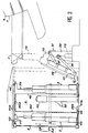
- FIG. 1 roughly schematizes a tank 1 with, in the rear lower part of its chassis 1a, a magazine 2 in which ammunition is stored 3.
- the loading system 10 according to the invention makes it possible to automatically route ammunition 3 from the magazine 2 up to the tube 5 of a barrel 6 supported by the turret 7 of the tank 1.
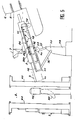
- the loading system 10 comprises a routing block 11 whose chassis 12 supports a cradle 15 for receiving ammunition 3 which is axially movable relative to the chassis 12, the ammunition 3 being itself axially displaceable relative to the cradle 15.
- the chassis 12 of the routing block 11 is constituted by at least two parallel beams 13 located opposite and connected to each other by transverse elements 14.
- the two opposite faces of the two beams 13 have each a longitudinal groove 16 having generally in cross section the shape of a C.
- the cradle 15 consists of a semi-cylindrical body 15a bordered by two longitudinal flanges 17 which each extend radially outwards.
- the cradle 15 is mounted parallel to the chassis 12 between the two longitudinal members 13 and each of its flanges 17 rotatably supports rollers 18 freely housed inside the grooves 16 associated with the chassis 12 of the routing block 11 to form pathways rolling and guiding of the cradle 15 during its movement relative to the chassis 12.
- a first drive device 20 which comprises, in the example considered here, a first motor member M1, preferably a gear motor, the output shaft of which 21 is integral with a pinion 22 which meshes with a longitudinal rack 23 fixed under the cradle 15 and extending parallel to the flanges 17 thereof.
- a second drive device 25 allows the ammunition 3 which rests on the cradle 15 to move relative thereto.
- This second drive system 25 comprises two endless belts 26 located respectively on either side of the cradle 15 and which each extend substantially over the length thereof.
- the two bands 26 are located slightly above the cradle 15, so that they can come into contact with the ammunition 3.
- each endless strip 26 is wound on two end rollers 27 and 28, with at least one intermediate guide roller 29.
- Each strip 26 thus wound is broken down into an external forward strand b1 and an internal internal return strand b2 to the cradle 15, considering the direction of drive of the strip 2 6 indicated by the arrow D.
- Each strip 26 supports projecting on its external face at least one shoe 26a and one tab 26b which, at the start, are located on the go b aller strand for reasons which will be explained later.
- the rollers 27 are motor rollers driven in rotation from the output shaft 30 of a second motor member M2, preferably a gear motor, situated for example towards a front end or end of the cradle 15 and placed under it.
- a movement transmission device (not shown) allows the output shaft 30 of the second motor M2 to simultaneously drive the two motor rollers 27 in rotation.
- the chassis 12 of the routing block 11 can be moved by means of a tilting device 35, integral with the chassis 1a, which is connected to the chassis 12 by means of two pivoting arms 36 and 37.
- the arm 36 is articulated at one end to the chassis 12 of the routing block 11 and at the other end to the output shaft 38 of a third motor member M3, preferably a gear motor, which controls the pivoting of the arm 36.
- the arm 37 is articulated at its two ends to the chassis 12 of the routing block 11 and to a plate 39 which supports the motor M3, respectively.
- the ammunition 3 is stored vertically inside the magazine 2 which has an outlet opening 2a located opposite the loading system 10.
- Each ammunition 3 is for example mounted in a support case 40.
- Two adjacent cases 40 are hingedly connected to each other so that all of the cases form a closed loop movable along a guide path defined inside the magazine.
- Each case 40 is guided at its upper part by at least one roller 42 which rolls one in an upper guide rail 41a, and at its lower part by at least one ball 43 which rolls in a lower guide rail 41b.
- the set of cases 40 is moved by a drive mechanism comprising a motor member M4, preferably a gear motor, the output shaft of which is coupled to a motion transmission device 44 to drive two horizontal chains, respectively upper 44a and lower 44b which mesh pins side 45 provided on the cases 40.
- a drive mechanism comprising a motor member M4, preferably a gear motor, the output shaft of which is coupled to a motion transmission device 44 to drive two horizontal chains, respectively upper 44a and lower 44b which mesh pins side 45 provided on the cases 40.
- a pivoting vertical arm 50 actuated by a motor member M5, preferably a gear motor, for tilting the munition 3 to 1 in a predetermined position. outside the store 2.
- the loading system 10 is in the rest position or inactive position, the routing block 11 and the cradle 15 being inclined relative to the vertical by an angle of approximately 30 °.
- the motor M3 of the tilting device 35 is actuated so as to bring the routing block 11 closer to the outlet opening of the magazine 2, while tilting it at an angle of about 45 °.
- the motor M5 is actuated to rotate the arm 50 which comes into contact with the ammunition 3 before tilting it so that it is directly received in the cradle 15.
- the second drive device 25 is actuated to advance the two endless bands 26 which run along the cradle 15 until the pads 26a pass over the return strands b2 and come into tight contact with the body 3a of the ammunition 2.
- the angle of inclination reached by the routing block 11 at the end of the second phase of the loading must be precisely defined. Indeed, the ammunition 3 must be in the axis of the tube 5 of the barrel 6 without the turret basket 7a can constitute an obstacle to the progress of the ammunition. Concretely, the angle of inclination that the routing block 11 can take is chosen according to the characteristics specific to the turret basket of the tank in question, and the angle of elevation of the barrel 6 is then adjusted accordingly.
- the cradle 15 is moved axially relative to the support routing block 11 by actuating the first drive device 20.
- the rotation of the motor M1 causes the rotation of the pinion 22 which positively engages the rack 23 secured to the cradle 15.
- the cradle 15 moves axially relative to the routing block 11, which has the effect of bringing the munition 3 closer to the tube 5 of the barrel 6. This thus reaches the position as shown in FIG. 5 where the front end of the munition is in the vicinity of the inlet of the tube 5 of the barrel 6.
- the second drive device 25 is again actuated so as to move the ammunition 3 relative to the cradle 15.
- the endless belts 26 are driven by the motor M2 and the pressure forces exerted by the pads on the body 3a of the ammunition 3 are sufficient to cause the axial displacement of the ammunition 3 relative to the cradle 15 and along it.
- the loading cycle of a munition 3 is finished, and after the projectile has been fired, a new cycle can start again in a manner similar to that described above once the loading system returned to the initial position.
- the invention is not limited to the embodiment described above, and it includes all the technical means equivalent to the means described without departing from the scope of the invention.
- the device for pivoting the ammunition 3 can be replaced by another device, the one which has been described above being particularly well suited in the case of a tank.
- the bands 26 with their pads 26a which firstly maintain the munition when the routing block 11 is moved to align the munition along the axis of the barrel tube, and secondly the movement of the ammunition relative to the cradle, and their legs 26b which then come into contact with the base of the ammunition to push the ammunition, could be replaced by a single device adapted to the space available inside the tank, in particular the turret basket level.
Landscapes
- Engineering & Computer Science (AREA)
- General Engineering & Computer Science (AREA)
- Warehouses Or Storage Devices (AREA)
- Toys (AREA)
- Replacing, Conveying, And Pick-Finding For Filamentary Materials (AREA)
Abstract
Description
La présente invention concerne un système de chargement automatique d'une munition dans la chambre du tube d'un canon, en particulier du canon-d'un char.The present invention relates to a system for automatically loading ammunition into the chamber of the barrel of a cannon, in particular of the barrel of a tank.
D'une manière générale, les munitions stockées dans un char sont prélevées dans un magasin et chargées manuellement dans le tube du canon. Le magasin principal, où les munitions sont stockées à l'horizontale, est situé dans la tourelle du char, c'est-à-dire en partie haute et dans une zone pas trop éloignée du canon pour faciliter les opérations de chargement. Or, il est reconnu que la tourelle d'un char est une zone vulnérable mal protégée des projectiles de l'ennemi. Il est tout autant reconnu que la zone la moins exposée se situe en partie basse et à l'arrière du char par rapport au poste de pilotage. Cependant si le choix d'un tel emplacement pour le magasin de munitions offre des conditions de sécurité maximum pour l'équipage, il n'est pas sans poser le problème de l'acheminement des munitions jusqu'au tube du canon.Generally, the ammunition stored in a tank is taken from a store and loaded manually into the barrel. The main store, where the ammunition is stored horizontally, is located in the tank turret, that is to say at the top and in an area not too far from the barrel to facilitate loading operations. However, it is recognized that the turret of a tank is a vulnerable area poorly protected from enemy projectiles. It is equally recognized that the least exposed area is located in the lower part and aft of the tank in relation to the cockpit. However, if the choice of such a location for the ammunition store offers maximum safety conditions for the crew, it is not without posing the problem of transporting the ammunition to the barrel tube.
Le but de l'invention est de permettre un tel choix d'emplacement pour le magasin de munitions d'un char en résolvant le problème de l'acheminement des munitions d'une manière automatique à partir d'une zone de stockage fixe située en partie basse du châssis du char et à l'arrière de celui-ci.The object of the invention is to allow such a choice of location for the ammunition store of a tank by solving the problem of the delivery of ammunition in an automatic manner from a fixed storage area located in lower part of the chassis of the tank and at the rear of it.
A cet effet, l'invention propose un système de chargement automatique d'une munition dans la chambre du tube d'un canon, en particulier du canon d'un char, caractérisé en ce qu'il comprend un bloc d'acheminement qui supporte un berceau sur lequel est déposée une munition extraite d'un magasin de stockage, des moyens pour déplacer le bloc d'acheminement de manière à aligner la munition suivant l'axe du tube du canon, des moyens pour déplacer le berceau par rapport au bloc d'acheminement pour amener la munition au voisinage de l'entrée du tube du canon et des moyens pour déplacer la munition par rapport au berceau afin de l'engager à l'intérieur de la chambre.To this end, the invention provides an automatic loading system of ammunition in the chamber of the tube of a cannon, in particular of the barrel of a tank, characterized in that it comprises a routing block which supports a cradle on which is deposited an ammunition extracted from a storage magazine, means for moving the routing block so as to align the ammunition along the axis of the barrel tube, means for moving the cradle relative to the block routing to bring the ammunition in the vicinity of the entry of the barrel tube and means for moving the ammunition by report to the cradle in order to engage it inside the room.
Selon un mode de réalisation de l'invention, le bloc d'acheminement du système de chargement comprend un châssis constitué d'au moins deux longerons parallèles situés en vis-à-vis, le berceau est un corps semi-cylindrique placé entre les deux longerons du châssis du bloc d'acheminement et bordé de deux rebords longitudinaux qui supportent à rotation des galets déplaçables le long de chemins de roulement aménagés dans les deux longerons du châssis du bloc d'acheminement, le berceau est déplaçable axialement par rapport au bloc d'acheminement par un premier dispositif d'entraînement du type pignon-crémaillère actionné par un premier moteur, et la munition est déplaçable axialement par rapport au berceau par un second dispositif comprenant deux bandes sans fin situées de part et d'autre du berceau avec des patins et des pattes qui viennent au contact de la munition pour la maintenir dans un premier temps sur le berceau et la déplacer ensuite par rapport au berceau pour l'engager dans le tube du canon.According to one embodiment of the invention, the routing block of the loading system comprises a chassis consisting of at least two parallel beams located opposite, the cradle is a semi-cylindrical body placed between the two longitudinal members of the chassis of the routing block and bordered by two longitudinal flanges which rotationally support rollers movable along raceways arranged in the two longitudinal members of the chassis of the routing block, the cradle is axially movable relative to the block of routing by a first drive device of the rack and pinion type actuated by a first motor, and the ammunition is axially displaceable relative to the cradle by a second device comprising two endless bands situated on either side of the cradle with skids and legs which come into contact with the ammunition to first maintain it on the cradle and then move it relative to the cradle u to engage it in the barrel tube.
Selon une autre caractéristique de l'invention, le bloc d'acheminement du système de chargement est déplaçable entre la sortie du magasin où une munition est basculée sur le berceau, et une position déterminée où la munition est située dans l'axe du tube du canon, position à partir de laquelle sont ensuite actionnés les premier et second dispositifs d'entraînement précités.According to another characteristic of the invention, the routing block of the loading system is movable between the exit from the store where an ammunition is tilted on the cradle, and a determined position where the ammunition is located in the axis of the tube of the barrel, position from which the first and second aforementioned drive devices are then actuated.
Un tel système de chargement automatique permet de diminuer la vulnérabilité du char, d'offrir une meilleure sécurité à l'équipage tout en le dispensant d'accomplir les opérations de chargement manuel des munitions.Such an automatic loading system makes it possible to reduce the vulnerability of the tank, to offer better security to the crew while dispensing them from performing manual loading operations of the ammunition.
D'autres avantages, caractéristiques et détails de l'invention ressortiront de la description explicative qui va suivre faite en référence aux Dessins annexés donnés uniquement à titre d'exemple et dans lesquels :
- la figure 1 est une vue schématique pour montrer le principe de chargement d'une munition dans un char équipé du système conforme à l'invention,
- le figure 2 est une vue en perspective du bloc d'acheminement d'une munition depuis le magasin jusqu'au tube du canon,
- la figure 2a est une vue en coupe suivant la ligne II-II de la figure 2,
- et les figures 3 à 6 sont des vues en coupe longitudinales schématiques montrant les différentes positions prises par le système de chargement lors de l'acheminement d'une munition depuis le magasin jusqu'au tube du canon.
- FIG. 1 is a schematic view to show the principle of loading ammunition into a tank equipped with the system according to the invention,
- FIG. 2 is a perspective view of the block for routing ammunition from the magazine to the barrel tube,
- FIG. 2a is a sectional view along the line II-II of FIG. 2,
- and Figures 3 to 6 are schematic longitudinal sectional views showing the different positions taken by the loading system during the delivery of ammunition from the magazine to the barrel tube.
La figure 1 schématise grossièrement un char 1 avec dans la partie basse arrière de son châssis la, un magasin 2 dans lequel sont stockées des munitions 3. Le système de chargement 10 conforme à l'invention permet d'acheminer automatiquement une munition 3 depuis le magasin 2 jusqu'au tube 5 d'un canon 6 supporté par la tourelle 7 du char 1.FIG. 1 roughly schematizes a tank 1 with, in the rear lower part of its
En se reportant aux figures 2 et 2a, le système de chargement 10 comprend un bloc d'acheminement 11 dont le châssis 12 supporte un berceau 15 de réception d'une munition 3 qui est déplaçable axialement par rapport au châssis 12, la munition 3 étant elle-même déplaçable axialement par rapport au berceau 15.Referring to Figures 2 and 2a, the
Le châssis 12 du bloc d'acheminement 11 est constitué par au moins deux longerons parallèles 13 situés en vis-à-vis et reliés l'un à l'autre par des éléments transversaux 14. Les deux faces en regard des deux longerons 13 présentent chacune une rainure longitudinale 16 ayant globalement en section transversale la forme d'un C.The
Le berceau 15 est constitué d'un corps semi-cylindrique 15a bordé de deux rebords longitudinaux 17 qui s'étendent chacun radialement vers l'extérieur. Le berceau 15 est monté parallèlement au châssis 12 entre les deux longerons 13 et chacun de ses rebords 17 supporte à rotation des galets 18 logés librement à l'intérieur des rainures 16 associées du châssis 12 du bloc d'acheminement 11 pour former des chemins de roulement et de guidage du berceau 15 lors de son déplacement par rapport au châssis 12.The
Le déplacement axial du berceau 15 par rapport au châssis 12 est assuré par un premier dispositif d'entraînement 20 qui comprend, dans l'exemple considéré ici, un premier organe moteur M1, de préférence un moto-réducteur, dont l'arbre de sortie 21 est solidaire d'un pignon 22 qui engrène une crémaillère longitudinale 23 fixée sous le berceau 15 et s'étendant parallèlement aux rebords 17 de celui-ci.The axial movement of the
Un second dispositif d'entraînement 25 permet à la munition 3 qui repose sur le berceau 15 de se déplacer par rapport à celui-ci. Ce second système d'entraînement 25 comprend deux bandes sans fin 26 situées respectivement de part et d'autre du berceau 15 et qui s'étendent chacune sensiblement sur la longueur de celui-ci. Les deux bandes 26 sont situées légèrement au-dessus du berceau 15, pour qu'elles puissent venir au contact de la munition 3.A
Plus précisément, chaque bande sans fin 26 est enroulée sur deux galets d'extrémité 27 et 28, avec au moins un galet intermédiaire de guidage 29. Chaque bande 26 ainsi enroulée se décompose en un brin aller externe b₁ et un brin retour interne b₂ adjacent au berceau 15, en considérant le sens d'entraînement de la bande 2 6 indiqué par la flèche D. Chaque bande 26 supporte en saillie sur sa face externe au moins un patin 26a et une patte 26b qui, au départ, sont situés sur le brin aller b₁ pour des raisons qui seront explicitées plus loin.More specifically, each
Dans l'exemple considéré ici, les galets 27 sont des galets moteurs entraînés en rotation à partir de l'arbre de sortie 30 d'un second organe moteur M2, de préférence un moto-réducteur, situé par exemple vers une extrémité ou extrémité avant du berceau 15 et placé sous celui-ci. Bien entendu, un dispositif de transmission de mouvement (non représenté) permet à l'arbre de sortie 30 du second moteur M2 d'entraîner simultanément en rotation les deux galets moteurs 27.In the example considered here, the
En se reportant à la figure 3, le châssis 12 du bloc d'acheminement 11 est déplaçable au moyen d'un dispositif de basculement 35, solidaire du châssis 1a, qui est relié au châssis 12 par l'intermédiaire de deux bras pivotants 36 et 37. Le bras 36 est articulé par une extrémité au châssis 12 du bloc d'acheminement 11 et à l'autre extrémité à l'arbre de sortie 38 d'un troisième organe moteur M3, de préférence un moto-réducteur, qui commande le pivotement du bras 36. Le bras 37 est articulé à ses deux extrémités au châssis 12 du bloc d'acheminement 11 et à une platine 39 qui supporte le moteur M3, respectivement.Referring to FIG. 3, the
Dans l'exemple considéré ici, les munitions 3 sont stockées verticalement à l'intérieur du magasin 2 qui présente une ouverture de sortie 2a située en regard du système de chargement 10. Chaque munition 3 est par exemple montée dans un étui support 40. Deux étuis adjacents 40 sont reliés de manière articulée l'un à l'autre pour que l'ensemble des étuis forme une boucle fermée déplaçable le long d'un chemin de guidage défini à l'intérieur du magasin. Chaque étui 40 est guidé à sa partie supérieure par au moins un galet 42 qui roule un dans un rail de guidage supérieur 41a, et à sa partie inférieure par au moins une bille 43 qui roule dans un rail de guidage inférieur 41b. L'ensemble des étuis 40 est déplacé par un mécanisme d'entraînement comprenant un organe moteur M4, de préférence un moto-réducteur, dont l'arbre de sortie est couplé à un dispositif de transmission de mouvement 44 pour entraîner deux chaînes horizontales respectivement supérieure 44a et inférieure 44b qui engrènent des pions latéraux 45 prévus sur les étuis 40.In the example considered here, the
A l'intérieur du magasin et au voisinage de sa sortie, il est par exemple prévu un bras vertical pivotant 50 actionné, par un organe moteur M5, de préférence un moto-réducteur, pour faire basculer dans une position prédéterminée la munition 3 à l'extérieur du magasin 2.Inside the store and in the vicinity of its outlet, there is for example provided a pivoting
Il va être maintenant décrit le principe d'acheminement d'une munition 3 depuis le magasin 2 jusqu'à la chambre 5 du tube du canon 6 en se reportant successivement aux figures 3 à 6.There will now be described the principle of routing a
Sur la figure 3, le système de chargement 10 est en position de repos ou position inactive, le bloc d'acheminement 11 et le berceau 15 étant inclinés par rapport à la verticale d'un angle d'environ 30°.In FIG. 3, the
Dans une première phase illustrée à la figure 4, le moteur M3 du dispositif de basculement 35 est actionné de manière à rapprocher le bloc d'acheminement 11 de l'ouverture de sortie du magasin 2, tout en l'inclinant suivant un angle d'environ 45°. En supposant une munition 3 positionnée face à l'ouverture de sortie du magasin 2, le moteur M5 est actionné pour faire pivoter le bras 50 qui vient au contact de la munition 3 avant de la faire basculer de manière à ce que celle-ci soit directement reçue dans le berceau 15. Pour maintenir la munition 3 sur le berceau 15, on actionne le second dispositif d'entraînement 25 pour faire avancer les deux bandes sans fin 26 qui longent le berceau 15 jusqu'à ce que les patins 26a passent sur les brins retours b₂ et viennent en contact serré avec le corps 3a de la munition 2.In a first phase illustrated in FIG. 4, the motor M3 of the
Dans une deuxième phase, une fois la munition retenue par les patins 26a sur le berceau 15, on actionne à nouveau le moteur M3 du dispositif de basculement 35 pour amener l'ensemble bloc d'acheminement 11 - berceau 15 dans l'axe du tube 5 du canon 6, comme cela est représenté en traits forts à la figure 4.In a second phase, once the ammunition is retained by the
D'une manière générale, l'angle d'inclinaison atteint par le bloc d'acheminement 11 à la fin de la deuxième phase du chargement doit être défini avec précision. En effet, la munition 3 doit se trouver dans l'axe du tube 5 du canon 6 sans que le panier de tourelle 7a puisse constituer un obstacle au cheminement de la munition. Concrètement, on choisit l'angle d'inclinaison que peut prendre le bloc d'acheminement 11 en fonction des caractéristiques propres au panier de tourelle du char considéré, et on règle ensuite l'angle de site du canon 6 en conséquence.Generally, the angle of inclination reached by the
Dans une troisième phase, le berceau 15 est déplacé axialement par rapport au bloc d'acheminement 11 de support en actionnant le premier dispositif d'entraînement 20. La rotation du moteur M1 entraîne la rotation du pignon 22 qui engrène positivement la crémaillère 23 solidaire du berceau 15. Le berceau 15 se déplace axialement par rapport au bloc d'acheminement 11, ce qui a pour effet de rapprocher la munition 3 du tube 5 du canon 6. On atteint ainsi la position telle que représentée à la figure 5 où l'extrémité avant de la munition se trouve au voisinage de l'entrée du tube 5 du canon 6.In a third phase, the
Enfin, dans une dernière phase, on actionne à nouveau le second dispositif d'entraînement 25 de manière à déplacer la munition 3 par rapport au berceau 15. Les bandes sans fin 26 sont entraînées par le moteur M2 et les forces de pression exercées par les patins sur le corps 3a de la munition 3 sont suffisantes pour provoquer le déplacement axial de la munition 3 par rapport au berceau 15 et le long de celui-ci. Au cours de ce déplacement, chaque patte 26b des chaînes 26, au passage du brin aller b₁ au brin retour, vient au contact du culot 3b de la munition 1 pour la pousser et renforcer l'action des patins 26a dans le déplacement axial de la munition 1 par rapport au berceau 15 jusqu'à sa mise à poste dans le tube 5 du canon 6.Finally, in a last phase, the
Le cycle de chargement d'une munition 3 est terminé, et après le tir du projectile, un nouveau cycle peut recommencer d'une manière analogue à celle décrite précédemment une fois le système de chargement ramené en position initiale.The loading cycle of a
L'ensemble des opérations nécessaires au chargement d'une munition sont commandées automatiquement par un programme exécuté par un système informatique embarqué.All the operations necessary for loading ammunition are automatically controlled by a program executed by an on-board computer system.
Bien entendu, l'invention n'est pas limitée au mode de réalisation décrit précédemment, et elle comprend tous les moyens techniques équivalents des moyens décrits sans sortir du cadre de l'invention. En particulier, le dispositif d'extraction par pivotement des munitions 3 peut être remplacé par un autre dispositif, celui qui a été décrit précédemment étant particulièrement bien adapté dans le cas d'un char. Enfin les bandes 26 avec leurs patins 26a qui assurent dans un premier temps le maintien de la munition lorsque le bloc d'acheminement 11 est déplacé pour aligner la munition suivant l'axe du tube du canon, et dans un deuxième temps le déplacement de la munition par rapport au berceau, et leurs pattes 26b qui viennent ensuite au contact du culot de la munition pour pousser la munition, pourraient être remplacés par un seul et même dispositif adapté à l'espace disponible à l'intérieur du char, en particulier au niveau du panier de la tourelle.Of course, the invention is not limited to the embodiment described above, and it includes all the technical means equivalent to the means described without departing from the scope of the invention. In particular, the device for pivoting the
Claims (15)
Applications Claiming Priority (2)
| Application Number | Priority Date | Filing Date | Title |
|---|---|---|---|
| FR9112795A FR2682749B1 (en) | 1991-10-17 | 1991-10-17 | SYSTEM FOR AUTOMATICALLY LOADING AMMUNITION IN THE CHAMBER OF THE TUBE OF A CANON, PARTICULARLY THE CANNON OF A TANK, AND TANK EQUIPPED WITH SUCH A DEVICE. |
| FR9112795 | 1991-10-17 |
Publications (1)
| Publication Number | Publication Date |
|---|---|
| EP0538138A1 true EP0538138A1 (en) | 1993-04-21 |
Family
ID=9418009
Family Applications (1)
| Application Number | Title | Priority Date | Filing Date |
|---|---|---|---|
| EP92402828A Withdrawn EP0538138A1 (en) | 1991-10-17 | 1992-10-16 | Automatic ammunition loading system for a tank canon and tank equipped with such device |
Country Status (3)
| Country | Link |
|---|---|
| US (1) | US5335580A (en) |
| EP (1) | EP0538138A1 (en) |
| FR (1) | FR2682749B1 (en) |
Cited By (2)
| Publication number | Priority date | Publication date | Assignee | Title |
|---|---|---|---|---|
| US6460448B1 (en) * | 2000-08-17 | 2002-10-08 | The United States Of America As Represented By The Secretary Of The Army | Automated loader assist for mortars |
| FR3043190A1 (en) * | 2015-10-29 | 2017-05-05 | Nexter Systems | REFOULOIR A OBUS |
Families Citing this family (4)
| Publication number | Priority date | Publication date | Assignee | Title |
|---|---|---|---|---|
| US5773747A (en) * | 1996-05-07 | 1998-06-30 | United Defense, Lp | Two-piece ammunition flick ram |
| FR2778235B1 (en) * | 1998-04-30 | 2000-06-02 | Giat Ind Sa | DEVICE FOR FEEDING AN ARTILLERY CANNON WITH AMMUNITION ELEMENTS |
| US6752063B2 (en) * | 2002-10-31 | 2004-06-22 | United Defense, L.P. | Multiple cell ammunition cradle |
| IT1404036B1 (en) * | 2010-12-17 | 2013-11-08 | Oto Melara Spa | ARMORED VEHICLE WITH IMPROVED STRUCTURE. |
Citations (3)
| Publication number | Priority date | Publication date | Assignee | Title |
|---|---|---|---|---|
| DE3413516A1 (en) * | 1984-04-10 | 1985-10-17 | Industrieanlagen-Betriebsgesellschaft Mbh, 8012 Ottobrunn | Device for holding, guiding and driving cartridges |
| EP0368821A2 (en) * | 1988-10-12 | 1990-05-16 | Aktiebolaget Bofors | Ammunition feeding device incorporated in a tank |
| EP0450373A1 (en) * | 1990-04-04 | 1991-10-09 | KUKA Wehrtechnik GmbH | Loading mechanism for guns, especially armoured howitzers |
Family Cites Families (6)
| Publication number | Priority date | Publication date | Assignee | Title |
|---|---|---|---|---|
| US1310890A (en) * | 1919-07-22 | Planoqftaph co | ||
| US1602568A (en) * | 1924-07-21 | 1926-10-12 | Thomas A Conlon | Mechanical loader for cannon |
| US2112853A (en) * | 1936-05-04 | 1938-04-05 | Victor F Lucht | Loader for guns |
| DE2818279C2 (en) * | 1978-04-26 | 1983-12-29 | Krauss-Maffei AG, 8000 München | Device for the automatic conveying and / or loading of large-caliber, cartridged ammunition |
| US4823676A (en) * | 1985-10-04 | 1989-04-25 | Fmc Corporation | Autoloader for military vehicle |
| US4898071A (en) * | 1988-09-23 | 1990-02-06 | Fmc Corporation | Inflatable ammunition gripping device |
-
1991
- 1991-10-17 FR FR9112795A patent/FR2682749B1/en not_active Expired - Fee Related
-
1992
- 1992-10-16 US US07/961,627 patent/US5335580A/en not_active Expired - Fee Related
- 1992-10-16 EP EP92402828A patent/EP0538138A1/en not_active Withdrawn
Patent Citations (3)
| Publication number | Priority date | Publication date | Assignee | Title |
|---|---|---|---|---|
| DE3413516A1 (en) * | 1984-04-10 | 1985-10-17 | Industrieanlagen-Betriebsgesellschaft Mbh, 8012 Ottobrunn | Device for holding, guiding and driving cartridges |
| EP0368821A2 (en) * | 1988-10-12 | 1990-05-16 | Aktiebolaget Bofors | Ammunition feeding device incorporated in a tank |
| EP0450373A1 (en) * | 1990-04-04 | 1991-10-09 | KUKA Wehrtechnik GmbH | Loading mechanism for guns, especially armoured howitzers |
Cited By (2)
| Publication number | Priority date | Publication date | Assignee | Title |
|---|---|---|---|---|
| US6460448B1 (en) * | 2000-08-17 | 2002-10-08 | The United States Of America As Represented By The Secretary Of The Army | Automated loader assist for mortars |
| FR3043190A1 (en) * | 2015-10-29 | 2017-05-05 | Nexter Systems | REFOULOIR A OBUS |
Also Published As
| Publication number | Publication date |
|---|---|
| FR2682749B1 (en) | 1993-12-10 |
| FR2682749A1 (en) | 1993-04-23 |
| US5335580A (en) | 1994-08-09 |
Similar Documents
| Publication | Publication Date | Title |
|---|---|---|
| EP0592344B1 (en) | Launching apparatus for clay pigeon targets | |
| EP0783094B1 (en) | Device for the transfer of propulsive charges for a magazine to a loading device | |
| CH427548A (en) | Brick grinding machine | |
| EP0694750B1 (en) | Ammunition feeding system for small or medium calibre arms | |
| FR2496249A1 (en) | Firearm automatic loading mechanism - comprises two magazines mounted symmetrically in relation to lengthwise axis and used selectively | |
| EP0538138A1 (en) | Automatic ammunition loading system for a tank canon and tank equipped with such device | |
| EP0953818B1 (en) | Feeding device in ammunition elements for an ordnance gun | |
| EP0538137B1 (en) | Ammunition magazine, especially for tanks | |
| EP2957487B1 (en) | Handling device for a vehicle track, device and method for changing track soles using such a handling device | |
| FR2610396A1 (en) | LOADING SYSTEM FOR CONTAINERS COMPRISING CARTRIDGE AMMUNITION | |
| EP0041017A1 (en) | Transport device for cylindrical objects such as ammunition | |
| EP0571285A1 (en) | Automatic firearm having a tiltable cartridge chamber for firing telescopic cyclindrical ammunition | |
| EP0706022A1 (en) | Ammunition feeding system for small or big calibre guns integrated in the turret of armoured vehicles | |
| EP0140782A1 (en) | Device for feeding and loading a gun with ammunition in any elevation or azimuth position | |
| EP0571265A1 (en) | Ammunition loading system for a pivoting cartridge chamber | |
| EP0125176B1 (en) | Military equipment comprising a turret provided with a mainly external gun | |
| FR2696538A1 (en) | Target launcher, esp. for clay pigeons | |
| FR3044753A1 (en) | DEVICE FOR HANDLING OBUS FOR PIECE OF ARTILLERY | |
| FR2524136A1 (en) | MECHANISM FOR SUPPLYING A DOUBLE-TUBE WEAPON WITH AMMUNITION | |
| FR2647888A1 (en) | Entirely automated firing unit with mortar | |
| FR2465660A1 (en) | STORAGE AND AUTOMATIC RECOVERY INSTALLATION FOR BEETS, TUBERS AND OTHER BULK PRODUCTS | |
| FR2884600A1 (en) | Ammunition feeding device for weapon e.g. naval weapon, has transfer units with guide pivotably mounted around axle and channel displaced relative to guide by ball pivot, and mounting clearance formed between channel and weapon | |
| FR2925149A1 (en) | Semi-automatic ammunition feed magazine, has cells arranged along drive train following pitch delimited by spacing of axles of consecutive cells, where drive train drives set of cells in rotation | |
| EP0571266B1 (en) | Ammunition loading system for a pivoting cartridge chamber | |
| EP0786068A1 (en) | Small or medium gauge multitube automatic fire arm of the gatling type, particularly intended to the firing of telescoped ammunition |
Legal Events
| Date | Code | Title | Description |
|---|---|---|---|
| PUAI | Public reference made under article 153(3) epc to a published international application that has entered the european phase |
Free format text: ORIGINAL CODE: 0009012 |
|
| AK | Designated contracting states |
Kind code of ref document: A1 Designated state(s): DE GB |
|
| 17P | Request for examination filed |
Effective date: 19930510 |
|
| 17Q | First examination report despatched |
Effective date: 19941025 |
|
| STAA | Information on the status of an ep patent application or granted ep patent |
Free format text: STATUS: THE APPLICATION HAS BEEN WITHDRAWN |
|
| 18W | Application withdrawn |
Withdrawal date: 19961012 |