EP0571285A1 - Automatic firearm having a tiltable cartridge chamber for firing telescopic cyclindrical ammunition - Google Patents
Automatic firearm having a tiltable cartridge chamber for firing telescopic cyclindrical ammunition Download PDFInfo
- Publication number
- EP0571285A1 EP0571285A1 EP93401294A EP93401294A EP0571285A1 EP 0571285 A1 EP0571285 A1 EP 0571285A1 EP 93401294 A EP93401294 A EP 93401294A EP 93401294 A EP93401294 A EP 93401294A EP 0571285 A1 EP0571285 A1 EP 0571285A1
- Authority
- EP
- European Patent Office
- Prior art keywords
- chamber
- ammunition
- carriage
- firing
- weapon according
- Prior art date
- Legal status (The legal status is an assumption and is not a legal conclusion. Google has not performed a legal analysis and makes no representation as to the accuracy of the status listed.)
- Granted
Links
Images


Classifications
-
- F—MECHANICAL ENGINEERING; LIGHTING; HEATING; WEAPONS; BLASTING
- F41—WEAPONS
- F41A—FUNCTIONAL FEATURES OR DETAILS COMMON TO BOTH SMALLARMS AND ORDNANCE, e.g. CANNONS; MOUNTINGS FOR SMALLARMS OR ORDNANCE
- F41A9/00—Feeding or loading of ammunition; Magazines; Guiding means for the extracting of cartridges
- F41A9/38—Loading arrangements, i.e. for bringing the ammunition into the firing position
- F41A9/45—Loading arrangements, i.e. for bringing the ammunition into the firing position the cartridge chamber or the barrel as a whole being tiltable or transversely slidable between a loading and a firing position
-
- F—MECHANICAL ENGINEERING; LIGHTING; HEATING; WEAPONS; BLASTING
- F41—WEAPONS
- F41A—FUNCTIONAL FEATURES OR DETAILS COMMON TO BOTH SMALLARMS AND ORDNANCE, e.g. CANNONS; MOUNTINGS FOR SMALLARMS OR ORDNANCE
- F41A15/00—Cartridge extractors, i.e. devices for pulling cartridges or cartridge cases at least partially out of the cartridge chamber; Cartridge ejectors, i.e. devices for throwing the extracted cartridges or cartridge cases free of the gun
- F41A15/02—Cartridge extractors, i.e. devices for pulling cartridges or cartridge cases at least partially out of the cartridge chamber; Cartridge ejectors, i.e. devices for throwing the extracted cartridges or cartridge cases free of the gun for revolver-type guns, e.g. revolvers
-
- F—MECHANICAL ENGINEERING; LIGHTING; HEATING; WEAPONS; BLASTING
- F41—WEAPONS
- F41A—FUNCTIONAL FEATURES OR DETAILS COMMON TO BOTH SMALLARMS AND ORDNANCE, e.g. CANNONS; MOUNTINGS FOR SMALLARMS OR ORDNANCE
- F41A15/00—Cartridge extractors, i.e. devices for pulling cartridges or cartridge cases at least partially out of the cartridge chamber; Cartridge ejectors, i.e. devices for throwing the extracted cartridges or cartridge cases free of the gun
- F41A15/20—Cartridge extractors, i.e. devices for pulling cartridges or cartridge cases at least partially out of the cartridge chamber; Cartridge ejectors, i.e. devices for throwing the extracted cartridges or cartridge cases free of the gun specially adapted for caseless-ammunition duds
Definitions
- the invention relates to an automatic weapon with tilting chamber for firing telescoped cylindrical ammunition, such as for example a medium caliber cannon.
- Telescoped cylindrical ammunition has been known since the early 1970s and has the advantage over conventional ammunition of being lighter and less bulky, the projectile being housed entirely inside a cylindrical shell of constant section, of so that these munitions can be loaded axially by one end of a chamber of the weapon and axially extract the empty casings by the other end of the chamber, which simplifies the mechanisms for extracting the empty casings.
- the recoil movement resulting from the firing of an ammunition is used for the angular displacement of the chamber between its firing and loading positions, and for the loading of a new ammunition into the chamber and the ejection of the empty cartridge case of the previously fired ammunition.
- the operation of the weapon therefore depends on the operation of the ammunition and results in significant accelerations and shocks, which stress the mechanisms severely.
- almost all of the movements necessary for loading ammunition is performed by the chamber, which is a very heavy piece whose displacement consumes a lot of energy and causes violent shocks.
- ammunition loaded in the chamber can only be fired when the receding parts of the weapon have been brought back into battery, which limits the rate of fire.
- the invention relates to an automatic weapon with tilting chamber for firing telescoped cylindrical ammunition, which is not subject to these drawbacks.
- It also relates to an automatic weapon of the aforementioned type allowing a floating shot, that is to say that a munition loaded in the chamber can be fired before the recoil of the receding parts of the weapon, thereby increasing the rate of fire.
- an automatic weapon with a tilting chamber for firing telescoped cylindrical munitions such as for example a medium caliber cannon, comprising a chamber for receiving an ammunition, arranged between a breech and a tube and tilting climb between a loading position and a firing position by pivoting around an eccentric shaft parallel to the tube, means for moving the chamber between these two positions, and means for supplying the chamber with ammunition, characterized in that the cylinder head, the tube and the pivot shaft of the chamber are fixedly carried by the same rigid structure which also carries the means for supplying ammunition as well as means with an electric motor for driving the means for moving the chamber and means for supplying munitlons, the latter being arranged behind the chamber in axial alignment with the latter in its loading position and comprising nt means movement of a munition in axial translation between a supply position and said chamber in its loading position, the introduction of a munition by the rear end of the chamber causing the extraction by the front end of the chamber of an empty cartridge case of a previously fired ammunition
- the operation of the weapon is ensured by an electric motor, which makes it possible to obtain greater regularity of the operating cycles and independence from the operation of the ammunition.
- the controlled movements of the chamber are limited to an alternating angular movement between its firing and loading positions, supply means driven by the electric motor being provided for axially displacing the munitions and introducing them one by one into the bedroom. This results in a significant reduction in the inertia of the parts of the weapon, the movements of which are controlled by the electric motor, and therefore a possible increase in the rate of fire.
- the pivot shaft of the chamber is driven in rotation about its axis by the aforementioned electric motor means and is connected to the chamber by transmission means transforming the rotational movement of the 'shaft in an alternative oscillation of the chamber between its loading and firing positions.
- these transmission means comprise on the one hand a carriage guided in translation on said rigid structure parallel to the pivot shaft of the chamber and moved in rectilinear reciprocating movement by said shaft by means a roller carried by the carriage and engaged in a helical groove of the shaft, and on the other hand a roller integral with the chamber and engaged in an oblique groove of said carriage.
- the chamber comprises at its axial ends circular flanges intended to engage, when the chamber is brought into its firing position, in corresponding grooves of the cylinder head and of a cylindrical sleeve of tube support.
- the means for supplying the chamber with ammunition comprise a supply carriage guided in translation on the aforementioned rigid structure and movable in rectilinear reciprocating movement to drive a munition from a position feed located behind the chamber in its loading position and introduce it into the chamber by axial translation, this carriage comprising a roller engaged in a helical groove of a longitudinal screw driven in rotation by the above-mentioned means with an electric motor .
- the means for supplying ammunition also comprise a supply star carrying a certain number of munitions and rotatably mounted around a longitudinal axis on said rigid structure, behind the chamber, for successively positioning the ammunition in the axis of the chamber in its loading position.
- the weapon allows a floating shot in burst at a rate high, the firing of an ammunition being carried out before the return to battery of all the recoiling parts.
- FIGS. 1 and 2 schematically represent the essential means of the weapon according to the invention.
- the rear end of the barrel 10 of the weapon is fixedly mounted in a sleeve 12 carried by a support 14 which is rigidly connected to the breech 16 by a lower beam 18 as well as by the longitudinal slides of a pivoting carriage of the tilting chamber, as will be seen below.
- the tilting chamber 20 arranged between the cylinder head 16 and the rear end of the tube 10 is a cylindrical part comprising an axial bore whose diameter and length are very slightly greater than the diameter and the length of the munitions to be fired. It pivots about the axis of a longitudinal shaft 22 parallel to the tube 10 and which is supported at its ends by the cylinder head 16 and the sleeve support 14.
- the front end of the shaft 22 carries a pinion 24 of rotary drive, which is itself connected by a gear train at the output shaft of an electric motor 26 placed under the tube 10 and the sleeve 12.
- the ammunition supply means which essentially comprise a supply star 28 carried by a rotation shaft 30 parallel to the tube 10, a supply carriage 32 movable in reciprocating rectilinear movement parallel to the tube 10 by a feed screw 34 carrying at its front end a pinion 36 connected by a gear train to the output shaft of the motor 26.
- the shaft 30 of the feed star 28 and the shaft of the feed screw 34 are carried at their ends by the cylinder head 16 and by a rear transmission and control box 38 which is rigidly connected to the cylinder head 16 by a longitudinal lower beam 40 and by longitudinal guides for guiding the feed carriage 32, as will be seen below.
- a percussion system 42 extends between the rear box 38 and the cylinder head 16, in the axis of the tube 10, and is controlled in axial displacement by the rear box 38. On this rear box is also fixed an electromagnet 44 trigger control.
- the sleeve 12 for fixing the tube 10 the cylinder head 16 and the rear box 38 are part of the same rigid structure which carries the tilting chamber 20 and its means of movement, as well as the means for supplying ammunition, the electric motor 20 and the associated gears. This entire assembly is subjected to a recoil movement when firing an ammunition, then to a battery return movement.
- the longitudinal shaft 22 mounted between the cylinder head 16 and the sleeve support 14 supports a screw 46 with a helical groove 48 in which is engaged the lower roller 50 of a carriage 52 guided in displacement in longitudinal slides 54 which rigidly connect the support sleeve 14 and cylinder head 16.
- the carriage 52 and its guide rails 54 are arranged between the shaft 22 and the tilting chamber 20.
- the latter is of substantially cylindrical shape and is fixedly mounted in a part 56 comprising at its ends axial two parallel arms 58 for pivotally mounting on the ends of the shaft 22.
- the lower face of this part 56 carries a roller 60 which is received in an oblique groove 62 of the upper face of the carriage 52 and whose ends 64 and 66 respectively define the loading position and the firing position of the tilting chamber 20.
- the shaft 22 performs one complete revolution per operating cycle of the weapon. It rotates the screw 46 which, by means of the lower roller 50 of the carriage 52, transforms the rotation of the shaft 22 into a rectilinear back and forth movement of the carriage 52 in its guide rails 54. This rectilinear movement of the carriage 52 is, by means of the roller 60 engaged in the oblique groove 62, transformed into an oscillating movement back and forth of the chamber 20 between its loading position shown in FIG. 3, and its firing position shown in FIG. 4.
- the roller 60 of the part 56 is at the rear end 64 of the groove 62 and the chamber 20 is in the loading position, while, when the carriage 52 is in its extreme rear position, the roller 60 of the part 56 is at the front end 66 of the groove 62 and the chamber 20 is in the firing position.
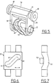
- the chamber 20 has at its axial ends two circular flanges 68 (Figure 5) intended to engage in grooves 70 of corresponding shape which are machined at the ends of the sleeve 12 and the cylinder head 16 ( Figures 8 and 9).
- each groove 70 extends circularly over 180 ° and is extended at its ends by two parallel guide ramps 72 between which the axial end engages corresponding to the chamber 20 when the latter is brought into its firing position.
- the circular flanges 68 engaged in the grooves 70 of the sleeve 12 and of the breech 16 ensure the connection between the breech, the chamber and the sleeve during firing of a munition, without the 'we have to provide a breech box as in a conventional weapon. Under these conditions, it is the chamber 20 which collects the tensile forces during the firing of an ammunition.
- the sleeve 12 comprises a longitudinal groove 74 which is formed throughout the thickness of its cylindrical wall and which extends from the rear end of the sleeve to the vicinity of its front end, to allow the extraction of an empty ammunition socket from the front of the chamber 20 when this chamber is in the loading position.
- the angular movement of the chamber 20 between its firing and loading positions is just sufficient so that the bore of the chamber is entirely released from the rear end of the tube 10, which makes it possible to limit the angular displacement from chamber 20 to around 30 and thus accelerate the rate of fire.
- an ejection arm 76 shown diagrammatically in FIGS. 10 and 11 is provided for moving an empty sleeve from an extraction position where it is partially engaged in the groove 74 of the sleeve 12 as far as an ejection position where it is released from this groove and aligned with an ejection chute (not shown).
- the ejection arm 76 is, in its middle part, pivotally mounted around a longitudinal axis 78 on the sleeve support 14, its upper end being intended to be applied under an empty socket 80 extracted from the chamber, while its lower end comprises a slot 82 in which is engaged a finger 84 carried by one of the arms 58 of the part 56 for supporting the chamber 20.
- the chamber 20 In the position of FIG. 10, the chamber 20 is in the loading position, the upper end of the arm 76 is applied under an empty socket 80 extracted from the chamber and the front end of which is supported on a retaining carriage 86 movable in reciprocating rectilinear movement as will be seen below, the empty socket 80 also being supported in this position by the longitudinal groove 74 of the sleeve 12.
- FIGS. 12 et seq. To describe the means for supplying ammunition and their operation.
- the feed star 28 mounted on the longitudinal shaft 30 can carry four telescoped cylindrical munitions 88 which are brought successively, by rotation of the star 28 on a fifth of a turn, in a position lower than the level of the feed carriage 32 and in axial alignment with the chamber 20 brought into its loading position .
- This feed carriage 32 is guided in rectilinear movement in two longitudinal slides 90 which rigidly connect the rear box 38 to the cylinder head 16, the carriage 32 thus being disposed between the feed star 28 and the feed screw 34.
- This comprises a stepped helical groove 92 ( Figures 1 and 2) in which are engaged a roller 94 and a sliding shoe 96 which are vertically superimposed and fixed under the carriage 32.
- the roller 94 is engaged in the widest part of the groove 92 while the shoe 96 is engaged in the narrowest part and contributes to the passage of the roller in the intersections of the groove 92 of the screw during the rotation of the latter, this groove 92 being not crossed to allow a back and forth movement of the carriage 32 during the continuous rotation of the screw 34 in a determined direction.
- the screw 34 is rotated at a speed three times higher than the shaft 22 for moving the tilting chamber 20.
- the feed carriage 32 is connected to the retaining carriage 86 described with reference to FIGS. 10 and 11, by means of a rigid rod 98 and a latch support 100 (FIGS. 13 et seq.), The carriage retainer 86 being itself guided in translation on two parallel longitudinal rods 102 which are fixed at their ends to the sleeve 12 and to the sleeve support 14, respectively (FIG. 1).
- the carriage 32 comprises a lateral tab 104 engaged in an elongated opening in the latch support 100 and allowing limited longitudinal movement of the carriage 32 relative to the latch support 100.
- a latch 106 such as a roller or a ball, is engaged in a small transverse groove of the support 100 and in a longitudinal groove 108 of the rigid structure, at the ends of which are provided locking pins 110 biased by springs to come to engage in a notch 112 of the lock support and immobilize that here in position.
- the tab 104 of the carriage 32 has two parallel grooves 114 in each of which the lock 106 can partially engage in order to secure the carriage 32 and the lock support 100.
- the chamber 20 is in its loading position, in axial alignment with the carriage 32 and a munition 88 carried by the star 28.
- the chamber 20 comprises the empty socket 80 of a munition which has just been fired , the retaining carriage 86 being a few millimeters from the front face of the chamber 20, while the supply carriage 32 is a few millimeters from the ammunition 88 to be loaded into the chamber 20.
- the latch support 100 is immobilized by a pin 110 which is engaged in the notch 112 of this support.
- the lock 106 As soon as the clearances have been caught up and the side tab 104 of the carriage 32 is in abutment on the front end of the slot of the lock support, the lock 106, guided by the groove 108, engages in a groove 114 of the tab 104 and secures the carriage 32 and the lock support 100. The lock support is then driven forward by the carriage 32 and emerges from the pin 110, compressing the spring of this pin.
- the carriage 32 continues to move forward ( Figures 17 to 20) to introduce the ammunition 88 into the chamber 20, this ammunition 88 pushing the empty socket 80 outside the chamber to engage it on the longitudinal groove 74 sleeve support 12 ( Figure 8), where it is also supported by the upper end of the ejection arm 76 ( Figure 10).
- the front end of the empty socket 80 is in abutment on the retaining carriage 86, which is itself moved forward on the rods 102.
- the carriage 32 can then move rearward over a short distance to disengage from the chamber 20 (FIGS. 23 and 24), without driving the lock support and therefore without moving the retaining carriage 86 backwards.
- the empty socket 80 is moved from its extraction position to its ejection position by the ejection arm 76 (FIG. 11), which frees the passage to the rear of the retaining carriage 86.
- the chamber 20 is moved to its firing position to bring the ammunition 88 into axial alignment with the percussion system 42 and with the tube 10.
- a calibration cam 116 located at the front of the chamber 20 makes it possible to correctly reposition the ammunition 88 inside the chamber 20.
- the feed carriage 32 is again secured to the latch support 100 by the latch 106 engaged in a groove 114 in the side tab of the carriage 32, so that the carriage 32, the latch support 100 and the retaining carriage 86 can be brought back into their rear position of Figures 13 and 14.
- the weapon according to the invention makes it possible to carry out a floating shot without waiting for the receding parts to return to the battery, that is to say a shot at a very high rate.
- the supply star 28 is, in known manner, itself supplied with ammunition from a magazine by means which automatically follow the movements of recoil and return to the battery of the weapon.
Abstract
Description
L'invention concerne une arme automatique à chambre basculante pour le tir de munitions cylindriques télescopées, telle par exemple qu'un canon de moyen calibre.The invention relates to an automatic weapon with tilting chamber for firing telescoped cylindrical ammunition, such as for example a medium caliber cannon.
Les munitions cylindriques télescopées sont connues depuis le début des années 1970 et présentent l'avantage par rapport aux munitions classiques d'être moins lourdes et moins encombrantes, le projectile étant logé entièrement à l'intérieur d'une douille cylindrique à section constante, de sorte qu'on peut charger ces munitions axialement par une extrémité d'une chambre de l'arme et extraire axialement les douilles vides par l'autre extrémité de la chambre, ce qui simplifie les mécanismes d'extraction des douilles vides.Telescoped cylindrical ammunition has been known since the early 1970s and has the advantage over conventional ammunition of being lighter and less bulky, the projectile being housed entirely inside a cylindrical shell of constant section, of so that these munitions can be loaded axially by one end of a chamber of the weapon and axially extract the empty casings by the other end of the chamber, which simplifies the mechanisms for extracting the empty casings.
On connaît déjà, par le brevet US-4 357 857, une arme automatique pour le tir de munitions cylindriques télescopées, dans laquelle une chambre agencée entre une culasse et un tube de canon est montée basculante autour d'un axe parallèle à l'axe du tube entre une position de tir où elle est disposée coaxialement au tube, et une position de chargement où elle est écartée angulairement de la culasse et du tube pour recevoir une nouvelle munition et permettre l'éjection de la douille vide de la munition précédemment tirée.Already known, from patent US-4 357 857, an automatic weapon for firing telescoped cylindrical ammunition, in which a chamber arranged between a breech and a barrel tube is pivotally mounted around an axis parallel to the axis of the tube between a firing position where it is arranged coaxially with the tube, and a loading position where it is angularly separated from the breech and the tube to receive a new ammunition and allow the ejection of the empty casing of the ammunition previously fired .
Dans cette arme connue, on utilise le mouvement de recul résultant du tir d'une munition pour le déplacement angulaire de la chambre entre ses positions de tir et de chargement, et pour le chargement d'une nouvelle munition dans la chambre et l'éjection de la douille vide de la munition précédemment tirée. Le fonctionnement de l'arme dépend donc du fonctionnement des munitions et se traduit par des accélérations et des chocs importants, qui sollicitent les mécanismes de façon sévère. De plus, dans cette arme, la quasi-totalité des mouvements nécessaires au chargement d'une munition est effectuée par la chambre, qui est une pièce très lourde dont le déplacement consomme beaucoup d'énergie et provoque des chocs violents. Par ailleurs, une munition chargée dans la chambre ne peut être tirée que lorsque les pièces reculantes de l'arme ont été ramenées en batterie ce qui limite la cadence de tir.In this known weapon, the recoil movement resulting from the firing of an ammunition is used for the angular displacement of the chamber between its firing and loading positions, and for the loading of a new ammunition into the chamber and the ejection of the empty cartridge case of the previously fired ammunition. The operation of the weapon therefore depends on the operation of the ammunition and results in significant accelerations and shocks, which stress the mechanisms severely. In addition, in this weapon, almost all of the movements necessary for loading ammunition is performed by the chamber, which is a very heavy piece whose displacement consumes a lot of energy and causes violent shocks. Furthermore, ammunition loaded in the chamber can only be fired when the receding parts of the weapon have been brought back into battery, which limits the rate of fire.
L'invention a pour objet une arme automatique à chambre basculante pour le tir de munitions cylindriques télescopées, qui ne soit pas soumise à ces inconvénients.The invention relates to an automatic weapon with tilting chamber for firing telescoped cylindrical ammunition, which is not subject to these drawbacks.
Elle a également pour objet une arme automatique du type précité permettant un tir flottant, c'est-à-dire qu'une munition chargée dans la chambre peut être tirée avant le retour en batterie des pièces reculantes de l'arme, en augmentant ainsi la cadence de tir.It also relates to an automatic weapon of the aforementioned type allowing a floating shot, that is to say that a munition loaded in the chamber can be fired before the recoil of the receding parts of the weapon, thereby increasing the rate of fire.
Elle a encore pour objet une arme du type précité dont le fonctionnement est indépendant du fonctionnement des munitions.It also relates to a weapon of the aforementioned type, the operation of which is independent of the operation of the ammunition.
L'invention propose à cet effet une arme automatique à chambre basculante pour le tir de munitions cylindriques télescopées, telle par exemple qu'un canon de moyen calibre, comprenant une chambre de réception d'une munition, agencée entre une culasse et un tube et montée basculante entre une position de chargement et une position de tir par pivotement autour d'un arbre excentré parallèle au tube, des moyens de déplacement de la chambre entre ces deux positions, et des moyens d'alimentation de la chambre en munitions, caractérisée en ce que la culasse, le tube et l'arbre de pivotement de la chambre sont portés fixement par une même structure rigide qui porte également les moyens d'alimentation en munitions ainsi que des moyens à moteur électrique d'entraînement des moyens de déplacement de la chambre et des moyens d'alimentation en munitlons, ces derniers étant disposés derrière la chambre en alignement axial avec celle-ci dans sa position de chargement et comprenant des moyens de déplacement d'une munition en translation axiale entre une position d'alimentation et ladite chambre dans sa position de chargement, l'introduction d'une munition par l'extrémité arrière de la chambre provoquant l'extraction par l'extrémité avant de la chambre d'une douille vide d'une munition précédemment tirée.To this end, the invention proposes an automatic weapon with a tilting chamber for firing telescoped cylindrical munitions, such as for example a medium caliber cannon, comprising a chamber for receiving an ammunition, arranged between a breech and a tube and tilting climb between a loading position and a firing position by pivoting around an eccentric shaft parallel to the tube, means for moving the chamber between these two positions, and means for supplying the chamber with ammunition, characterized in that the cylinder head, the tube and the pivot shaft of the chamber are fixedly carried by the same rigid structure which also carries the means for supplying ammunition as well as means with an electric motor for driving the means for moving the chamber and means for supplying munitlons, the latter being arranged behind the chamber in axial alignment with the latter in its loading position and comprising nt means movement of a munition in axial translation between a supply position and said chamber in its loading position, the introduction of a munition by the rear end of the chamber causing the extraction by the front end of the chamber of an empty cartridge case of a previously fired ammunition.
Ainsi, selon l'invention, le fonctionnement de l'arme est assuré par un moteur électrique, ce qui permet d'obtenir une plus grande régularité des cycles de fonctionnement et une indépendance vis-à-vis du fonctionnement des munitions. Par ailleurs, les déplacements commandés de la chambre sont limités à un déplacement angulaire alternatif entre ses positions de tir et de chargement, des moyens d'alimentation entraînés par le moteur électrique étant prévus pour déplacer axialement les munitions et les introduire une à une dans la chambre. Il en résulte une réduction importante de l'inertie des pièces de l'arme dont les mouvements sont commandés par le moteur électrique, et donc une augmentation possible de la cadence de tir.Thus, according to the invention, the operation of the weapon is ensured by an electric motor, which makes it possible to obtain greater regularity of the operating cycles and independence from the operation of the ammunition. Furthermore, the controlled movements of the chamber are limited to an alternating angular movement between its firing and loading positions, supply means driven by the electric motor being provided for axially displacing the munitions and introducing them one by one into the bedroom. This results in a significant reduction in the inertia of the parts of the weapon, the movements of which are controlled by the electric motor, and therefore a possible increase in the rate of fire.
Selon une autre caractéristique de l'invention, l'arbre de pivotement de la chambre est entraîné en rotation autour de son axe par les moyens à moteur électrique précites et est relié à la chambre par des moyens de transmission transformant le mouvement de rotation de l'arbre en une oscillation alternative de la chambre entre ses positions de chargement et de tir.According to another characteristic of the invention, the pivot shaft of the chamber is driven in rotation about its axis by the aforementioned electric motor means and is connected to the chamber by transmission means transforming the rotational movement of the 'shaft in an alternative oscillation of the chamber between its loading and firing positions.
Dans un mode de réalisation particulier de l'invention, ces moyens de transmission comprennent d'une part un chariot guidé en translation sur ladite structure rigide parallèlement à l'arbre de pivotement de la chambre et déplacé en mouvement alternatif rectiligne par ledit arbre au moyen d'un galet porté par le chariot et engagé dans une rainure hélicoïdale de l'arbre, et d'autre part un galet solidaire de la chambre et engagé dans une rainure oblique dudit chariot.In a particular embodiment of the invention, these transmission means comprise on the one hand a carriage guided in translation on said rigid structure parallel to the pivot shaft of the chamber and moved in rectilinear reciprocating movement by said shaft by means a roller carried by the carriage and engaged in a helical groove of the shaft, and on the other hand a roller integral with the chamber and engaged in an oblique groove of said carriage.
Ces moyens de déplacement de la chambre permettent de contrôler les accélérations de la chambre au cours de ses déplacements, et donc de réduire les chocs en fin de déplacement.These means of displacement of the chamber make it possible to control the accelerations of the chamber during its displacements, and therefore to reduce the shocks at the end of displacement.
Selon une autre caractéristique de l'invention, la chambre comporte à ses extrémités axiales des collerettes circulaires destinées à s'engager, quand la chambre est amenée dans sa position de tir, dans des rainures correspondantes de la culasse et d'un manchon cylindrique de support du tube.According to another characteristic of the invention, the chamber comprises at its axial ends circular flanges intended to engage, when the chamber is brought into its firing position, in corresponding grooves of the cylinder head and of a cylindrical sleeve of tube support.
Ces collerettes circulaires engagées dans les rainures correspondantes de la culasse et du manchon de support du tube, assurent alors la liaison de la culasse et du tube à la chambre en position de tir, ce qui se traduit par un allégement important de l'arme du fait de la suppression de la boîte de culasse généralement prévue dans une arme de type classique.These circular flanges engaged in the corresponding grooves of the breech and of the tube support sleeve, then ensure the connection of the breech and the tube to the chamber in the firing position, which results in a significant reduction in the weapon of the made the removal of the breech box generally provided in a conventional type weapon.
Selon encore une autre caractéristique de l'invention, les moyens d'alimentation de la chambre en munitions comprennent un chariot d'alimentation guidé en translation sur la structure rigide précitée et déplaçable en mouvement alternatif rectiligne pour entraîner une munition à partir d'une position d'alimentation située en arrière de la chambre dans sa position de chargement et l'introduire dans la chambre par translation axiale, ce chariot comportant un galet engagé dans une rainure hélicoïdale d'une vis longitudinale entraînée en rotation par les moyens précités à moteur électrique.According to yet another characteristic of the invention, the means for supplying the chamber with ammunition comprise a supply carriage guided in translation on the aforementioned rigid structure and movable in rectilinear reciprocating movement to drive a munition from a position feed located behind the chamber in its loading position and introduce it into the chamber by axial translation, this carriage comprising a roller engaged in a helical groove of a longitudinal screw driven in rotation by the above-mentioned means with an electric motor .
Cela permet notamment de contrôler l'accélération d'une munition tout au long de son déplacement d'introduction dans la chambre en réduisant notamment les accélérations en fin de déplacement, ce qui facilite et régularise le chargement des munitions.This makes it possible in particular to control the acceleration of a munition throughout its movement of introduction into the chamber, in particular by reducing the accelerations at the end of movement, which facilitates and regularizes the loading of the ammunition.
Selon encore une autre caractéristique de l'invention, les moyens d'alimentation en munitions comprennent également une étoile d'alimentation portant un certain nombre de munitions et montée rotative autour d'un axe longitudinal sur ladite structure rigide, en arrière de la chambre, pour positionner successivement les munitions dans l'axe de la chambre dans sa position de chargement.According to yet another characteristic of the invention, the means for supplying ammunition also comprise a supply star carrying a certain number of munitions and rotatably mounted around a longitudinal axis on said rigid structure, behind the chamber, for successively positioning the ammunition in the axis of the chamber in its loading position.
Grâce au fait que la culasse et le tube de l'arme, la chambre basculante et les moyens d'alimentation en munitions sont montés sur une même structure rigide qui fait partie des pièces reculantes, l'arme permet un tir flottant en rafale à cadence élevée, le tir d'un munition étant effectué avant le retour en batterie de l'ensemble des pièces reculantes.Thanks to the fact that the breech and the barrel of the weapon, the tilting chamber and the means for supplying ammunition are mounted on the same rigid structure which is part of the receding parts, the weapon allows a floating shot in burst at a rate high, the firing of an ammunition being carried out before the return to battery of all the recoiling parts.
L'invention sera mieux comprise et d'autres caractéristiques, détails et avantages de celle-ci apparaitront plus clairement à la lecture de la description qui suit, faite à titre d'exemple en réference aux dessins annexés dans lesquels :
- les figures 1 et 2 sont des vues schématiques partielles en coupe longitudinale de l'arme selon l'invention, la figure 1 représentant la chambre basculante dans sa position de chargement, et la figure 2 la représentant dans sa position de tir;
- la figure 3 est une vue schématique à plus grande échelle en coupe transversale selon la ligne A-A de la figure 1, représentant la chambre dans sa position de chargement;
- la figure 4 est une vue semblable à la figure 3, mais représentant la chambre dans sa position de tir;
- la figure 5 est une vue schématique en perspective de la chambre, de son support et de sa vis de pivotement;
- les figures 6 et 7 sont des vues schématiques en plan et de côté du chariot de déplacement de la chambre;
- la figure 8 est une vue schématique en perspective, à plus grande échelle, du manchon de support du tube de l'arme;
- la figure 9 est une vue schématique partielle en coupe axiale, représentant la solidarisation de la chambre à la culasse et au manchon de support du tube;
- les figures 10 et 11 représentent schématiquement le bras d'éjection d'une douille vide et son fonctionnement;
- la figure 12 est une vue schématique à plus grande échelle en coupe transversale selon la ligne B-B de la figure 1;
- les figures 13 à 24 sont des vues de dessus illustrant le fonctionnement des moyens d'alimentation, les figures 14, 16, 18, 20, 22 et 24 représentant à plus grande échelle un détail des moyens d'alimentation représentés dans les figures 13, 15, 17, 19, 21 et 23.
- Figures 1 and 2 are partial schematic views in longitudinal section of the weapon according to the invention, Figure 1 showing the tilting chamber in its loading position, and Figure 2 showing it in its firing position;
- Figure 3 is a schematic view on a larger scale in cross section along the line AA of Figure 1, showing the chamber in its loading position;
- Figure 4 is a view similar to Figure 3, but showing the chamber in its firing position;
- Figure 5 is a schematic perspective view of the chamber, its support and its pivot screw;
- Figures 6 and 7 are schematic plan and side views of the carriage for moving the chamber;
- Figure 8 is a schematic perspective view, on a larger scale, of the gun barrel support sleeve;
- Figure 9 is a partial schematic view in axial section, showing the attachment of the chamber to the cylinder head and the tube support sleeve;
- Figures 10 and 11 schematically show the ejection arm of an empty socket and its operation;
- Figure 12 is a schematic view on a larger scale in cross section along the line BB of Figure 1;
- FIGS. 13 to 24 are top views illustrating the operation of the supply means, FIGS. 14, 16, 18, 20, 22 and 24 showing on a larger scale a detail of the supply means represented in FIGS. 13, 15, 17, 19, 21 and 23.
On se réfère d'abord aux figures 1 et 2, qui représentent schématiquement les moyens essentiels de l'arme selon l'invention.Reference is first made to FIGS. 1 and 2, which schematically represent the essential means of the weapon according to the invention.
L'extrémité arrière du tube 10 de l'arme est montée fixement dans un manchon 12 porté par un support 14 qui est relié rigidement à la culasse 16 par une poutre inférieure 18 ainsi que par les glissières longitudinales d'un chariot de pivotement de la chambre basculante, comme on le verra ci-après.The rear end of the
La chambre basculante 20 agencée entre la culasse 16 et l'extrémité arrière du tube 10 est une pièce cylindrique comportant un alésage axial dont le diamètre et la longueur sont très légèrement supérieurs au diamètre et à la longueur des munitions à tirer. Elle pivote autour de l'axe d'un arbre longitudinal 22 parallèle au tube 10 et qui est supporté à ses extrémités par la culasse 16 et le support de manchon 14. L'extrémité avant de l'arbre 22 porte un pignon 24 d'entraînement en rotation, qui est lui-même relié par un train d'engrenage à l'arbre de sortie d'un moteur électrique 26 disposé sous le tube 10 et le manchon 12.The
A l'arrière de la culasse 16 se trouvent les moyens d'alimentation en munitions, qui comprennent essentiellement une étoile d'alimentation 28 portée par un arbre de rotation 30 parallèle au tube 10, un chariot d'alimentation 32 déplaçable en mouvement rectiligne alternatif parallèlement au tube 10 par une vis d'alimentation 34 portant à son extrémité avant un pignon 36 relié par un train d'engrenage à l'arbre de sortie du moteur 26.At the rear of the
L'arbre 30 de l'étoile d'alimentation 28 et l'arbre de la vis d'alimentation 34 sont portés à leurs extrémités par la culasse 16 et par une boîte arrière 38 de transmission et de commande qui est reliée rigidement à la culasse 16 par une poutre inférieure longitudinale 40 et par des glissières longitudinales de guidage du chariot d'alimentation 32, comme on le verra ci-après.The
Un système de percussion 42 s'étend entre la boîte arrière 38 et la culasse 16, dans l'axe du tube 10, et est commandé en déplacement axial par la boîte arrière 38. Sur cette boîte arrière est également fixé un électro-aimant 44 de commande de détente.A
Les caractéristiques de la chambre basculante 20, de ses moyens de déplacement, et des moyens d'alimentation vont être décrits plus en détail en référence aux figures 3 et suivantes. On constate cependant déjà que le manchon 12 de fixation du tube 10, la culasse 16 et la boîte arrière 38 font partie d'une même structure rigide qui porte la chambre basculante 20 et ses moyens de déplacement, ainsi que les moyens d'alimentation en munitions, le moteur électrique 20 et les engrenages associés. Tout cet ensemble est soumis à un mouvement de recul lors du tir d'une munition, puis à un mouvement de retour en batterie.The characteristics of the
On va maintenant décrire plus en détaii la structure de la chambre basculante 20 et ses moyens de déplacement, en référence aux figures 3 à 7.We will now describe in more detail the structure of the
L'arbre longitudinal 22 monté entre la culasse 16 et le support de manchon 14 supporte une vis 46 à rainure hélicoïdale 48 dans laquelle est engagé le galet inférieur 50 d'un chariot 52 guidé en déplacement dans des glissières longitudinales 54 qui relient rigidement le support de manchon 14 et la culasse 16. Le chariot 52 et ses glissières de guidage 54 sont disposés entre l'arbre 22 et la chambre basculante 20. Celle-ci est de forme sensiblement cylindrique et est montée fixement dans une pièce 56 comprenant à ses extrémités axiales deux bras parallèles 58 de montage en pivotement sur les extrémités de l'arbre 22. La face inférieure de cette pièce 56 porte un galet 60 qui est reçu dans une rainure oblique 62 de la face supérieure du chariot 52 et dont les extrémités 64 et 66 définissent respectivement la position de chargement et la position de tir de la chambre basculante 20.The
L'arbre 22 effectue un tour complet par cycle de fonctionnement de l'arme. Il entraîne en rotation la vis 46 qui, par l'intermédiaire du galet inférieur 50 du chariot 52, transforme la rotation de l'arbre 22 en un déplacement rectiligne aller et retour du chariot 52 dans ses glissières de guidage 54. Ce déplacement rectiligne du chariot 52 est, par l'intermédiaire du galet 60 engagé dans la rainure oblique 62, transformé en un mouvement oscillant aller et retour de la chambre 20 entre sa position de chargement représentée en figure 3, et sa position de tir représentée en figure 4. De façon plus précise, lorsque le chariot 52 est dans sa position extrême avant, le galet 60 de la pièce 56 est à l'extrémité arrière 64 de la rainure 62 et la chambre 20 est en position de chargement, tandis que, quand le chariot 52 est dans sa position extrême arrière, le galet 60 de la pièce 56 est à l'extrémité avant 66 de la rainure 62 et la chambre 20 est en position de tir.The
La chambre 20 comporte à ses extrémités axiales deux collerettes circulaires 68 (figure 5) destinées à s'engager dans des rainures 70 de forme correspondante qui sont usinées aux extrémités du manchon 12 et de la culasse 16 (figures 8 et 9). Comme on peut le voir en figure 8 qui est une vue en perspective du manchon 12, chaque rainure 70 s'étend circulairement sur 180° et est prolongée à ses extrémités par deux rampes parallèles 72 de guidage entre lesquelles s'engage l'extrémité axiale correspondante de la chambre 20 lorsque celle- ci est amenée dans sa position de tir.The
Dans la position de tir de la chambre 20, les collerettes circulaires 68 engagées dans les rainures 70 du manchon 12 et de la culasse 16 assurent la liaison entre la culasse, la chambre et le manchon pendant le tir d'une munition, sans que l'on ait à prévoir une boîte de culasse comme dans une arme de type classique. Dans ces conditions, c'est la chambre 20 qui encaisse les efforts de traction pendant le tir d'une munition.In the firing position of the
Comme on le voit également en figure 8, le manchon 12 comprend une rainure longitudinale 74 qui est formée dans toute l'épaisseur de sa paroi cylindrique et qui s'étend de l'extrémité arrière du manchon jusqu'au voisinage de son extrémité avant, pour permettre l'extraction d'une douille vide de munition par l'avant de la chambre 20 lorsque cette chambre est en position de chargement. Dans ces conditions, le débattement angulaire de la chambre 20 entre ses positions de tir et de chargement est juste suffisant pour que l'alésage de la chambre soit entièrement dégagé de l'extrémité arrière du tube 10, ce qui permet de limiter le déplacement angulaire de la chambre 20 à environ 30 et d'accélérer ainsi la cadence de tir.As can also be seen in FIG. 8, the
Par ailleurs, on prévoit un bras d'éjection 76 représenté schématiquement aux figures 10 et 11 pour déplacer une douille vide d'une position d'extraction où elle est partiellement engagée dans la rainure 74 du manchon 12 jusque dans une position d'éjection où elle est dégagée de cette rainure et alignée avec une goulotte d'éjection (non représentée).Furthermore, an
Le bras d'éjection 76 est, dans sa partie médiane, monté pivotant autour d'un axe longitudinal 78 sur le support de manchon 14, son extrémité supérieure étant destinée à s'appliquer sous une douille vide 80 extraite de la chambre, tandis que son extrémité inférieure comporte une lumière 82 dans laquelle est engagé un doigt 84 porté par l'un des bras 58 de la pièce 56 de support de la chambre 20. Dans la position de la figure 10, la chambre 20 est en position de chargement, l'extrémité supérieure du bras 76 s'applique sous une douille vide 80 extraite de la chambre et dont l'extrémité avant est en appui sur un chariot de retenue 86 déplaçable en mouvement rectiligne alternatif comme on le verra ci-après, la douille vide 80 étant également supportée dans cette position par la rainure longitudinale 74 du manchon 12. Lorsque la chambre basculante est amenée dans sa position de tir comme représenté en figure 11, le pivotement du bras 58 se traduit par une rotation du bras d'éjection 76 autour de l'axe 78 dans le sens des aiguilles d'une montre pour amener la douille 80 en position d'éjection.The
Dans cette position d'éjection, la douille vide 80 a été dégagée à son extrémité avant du chariot de retenue 86 qui peut alors être déplacé vers l'arrière comme on le verra également dans ce qui suit.In this ejection position, the
On se réfère maintenant aux figures 12 et suivantes pour décrire les moyens d'alimentation en munitions et leur fonctionnement.Reference is now made to FIGS. 12 et seq. To describe the means for supplying ammunition and their operation.
Dans l'exemple de la figure 12, l'étoile d'alimentation 28 montée sur l'arbre longitudinal 30 peut porter quatre munitions cylindriques télescopées 88 qui sont amenées successivement, par rotation de l'étoile 28 sur un cinquième de tour, dans une position inférieure au niveau du chariot d'alimentation 32 et en alignement axial avec la chambre 20 amenée dans sa position de chargement.In the example of FIG. 12, the
Ce chariot d'alimentation 32 est guidé en déplacement rectiligne dans deux glissières longitudinales 90 qui relient rigidement la boîte arrière 38 à la culasse 16, le chariot 32 étant ainsi disposé entre l'étoile d'alimentation 28 et la vis d'alimentation 34.This
Celle-ci comporte une rainure hélicoïdale étagée 92 (figures 1 et 2) dans laquelle sont engagés un galet 94 et un patin de glissement 96 qui sont verticalement superposés et fixés sous le chariot 32. Le galet 94 est engagé dans la partie la plus large de la rainure 92 tandis que le patin 96 est engagé dans la partie la plus étroite et contribue au passage du galet dans les intersections de la rainure 92 de la vis pendant la rotation de celle-ci, cette rainure 92 étant à pas croisés pour permettre un mouvement aller retour du chariot 32 lors de la rotation continue de la vis 34 dans un sens déterminé. La vis 34 est entraînée en rotation à une vitesse trois fois plus élevée que l'arbre 22 de déplacement de la chambre basculante 20.This comprises a stepped helical groove 92 (Figures 1 and 2) in which are engaged a
Quand le chariot 32 est en position arrière et qu'il commence à se déplacer vers l'avant, il vient prendre appui sur l'extrémité arrière d'une munition 88 de l'étoile d'alimentation 28 et pousse cette munition vers l'avant pour l'introduire dans la chambre 20 en position de chargement.When the
Le chariot d'alimentation 32 est relié au chariot de retenue 86 décrit en référence aux figures 10 et 11, par l'intermédiaire d'une tige rigide 98 et d'un support de verrou 100 (figures 13 et suivantes), le chariot de retenue 86 étant lui-même guidé en translation sur deux tiges longitudinales parallèles 102 qui sont fixées à leurs extrémités sur le manchon 12 et sur le support 14 de manchon, respectivement (figure 1).The
Le chariot 32 comprend une patte latérale 104 engagée dans une lumière allongée du support de verrou 100 et permettant un déplacement longitudinal limité du chariot 32 par rapport au support de verrou 100. Un verrou 106, tel qu'un rouleau ou une bille, est engagé dans une petite rainure transversale du support 100 et dans une rainure longitudinale 108 de la structure rigide, aux extrémités de laquelle sont prévus des pions de blocage 110 sollicités par des ressorts pour venir s'engager dans une encoche 112 du support de verrou et immobiliser celui-ci en position. Par ailleurs, la patte 104 du chariot 32 comporte deux rainures parallèles 114 dans chacune desquelles le verrou 106 peut s'engager partiellement pour solidariser le chariot 32 et le support de verrou 100.The
Ces moyens d'alimentation en munitions fonctionnent de la façon suivante, décrite en référence aux figures 13 et suivantes.These ammunition supply means operate in the following manner, described with reference to FIGS. 13 and following.
En figure 13, la chambre 20 est dans sa position de chargement, en alignement axial avec le chariot 32 et une munition 88 portée par l'étoile 28. La chambre 20 comprend la douille vide 80 d'une munition qui vient d'être tirée, le chariot de retenue 86 étant à quelques millimètres de la face avant de la chambre 20, tandis que le chariot d'alimentation 32 est à quelques millimètres de la munition 88 à charger dans la chambre 20.In FIG. 13, the
Dans la position des figures 13 et 14, le verrou 106 n'est pas engagé dans une rainure 114 de la patte latérale du chariot 32, de sorte que celui-ci peut être déplacé vers l'avant sur une faible distance sans entraîner le support de verrou 100, pour rattraper les jeux nécessaires au fonctionnement (jeux entre l'extrémité avant du chariot 32 et l'extrémité arrière de la munition 88, entre l'extrémité avant de la munition 88 et l'extrémité arrière de la chambre 20, et entre l'extrémité avant de la chambre 20 et le chariot de retenue 86).In the position of FIGS. 13 and 14, the
Pendant ce petit déplacement vers l'avant du chariot 32 (figures 15 et 16), le support de verrou 100 est immobilisé par un pion 110 qui est engagé dans l'encoche 112 de ce support.During this small forward movement of the carriage 32 (Figures 15 and 16), the
Dès que les jeux ont été rattrapés et que la patte latérale 104 du chariot 32 est en appui sur l'extrémité avant de la lumière du support de verrou, le verrou 106, guidé par la rainure 108, vient s'engager dans une rainure 114 de la patte 104 et solidarise le chariot 32 et le support de verrou 100. Le support de verrou est alors entraîné vers l'avant par le chariot 32 et se dégage du pion 110, en comprimant le ressort de ce pion.As soon as the clearances have been caught up and the
Le chariot 32 continue son déplacement vers l'avant (figures 17 à 20) pour introduire la munition 88 dans la chambre 20, cette munition 88 poussant la douille vide 80 à l'extérieur de la chambre pour l'engager sur la rainure longitudinale 74 du support de manchon 12 (figure 8), où elle est également supportée par l'extrémité supérieure du bras d'éjection 76 (figure 10). Pendant ce mouvement d'extraction, l'extrémité avant de la douille vide 80 est en appui sur le chariot de retenue 86, qui est lui-même déplacé vers l'avant sur les tiges 102.The
En fin de course (figures 21 et 22), l'extrémité avant du chariot 32 pénètre légèrement à l'intérieur de la chambre 20, ce qui permet de garantir que la douille vide 80 a été complètement extraite de la chambre 20, en dépit des variations de longueur des douilles, qui sont dues aux tolérances de fabrication, aux variations des conditions d'ambiance et aux variations des conditions de tir.At the end of the race (Figures 21 and 22), the front end of the
Dans cette position extrême avant, le verrou 106 est dégagé de la rainure 114 de la patte latérale du chariot 32, le support de verrou 100 est immobilisé par un pion 110 et le chariot 32 est désolidarisé du support de verrou (figure 22).In this extreme forward position, the
Le chariot 32 peut alors se déplacer vers l'arrière sur une courte distance pour se dégager de la chambre 20 (figures 23 et 24), sans entraîner le support de verrou et donc sans déplacer vers l'arrière le chariot de retenue 86. Pendant ce temps, la douille vide 80 est déplacée de sa position d'extraction dans sa position d'éjection par le bras d'éjection 76 (figure 11), ce qui libère le passage vers l'arrière du chariot de retenue 86. Simultanément, la chambre 20 est déplacée vers sa position de tir pour amener la munition 88 en alignement axial avec le système de percussion 42 et avec le tube 10.The
Pendant ce mouvement, une came de calibrage 116 située à l'avant de la chambre 20 permet de repositionner correctement la munition 88 à l'intérieur de la chambre 20. Quand la chambre 20 est dans sa position de tir, le chariot d'alimentation 32 est à nouveau solidarisé du support de verrou 100 par le verrou 106 engagé dans une rainure 114 de la patte latérale du chariot 32, de sorte que le chariot 32, le support de verrou 100 et le chariot de retenue 86 peuvent être ramenés dans leur position arrière des figures 13 et 14.During this movement, a
De façon générale, le fonctionnement de l'arme selon l'invention est le suivant :
- en position arrêt sur détente, la chambre 20 est dans sa position de chargement, le chariot 52 de déplacement de la chambre est en position avant, le chariot d'alimentation 32 est en position arrière,
une munition 88 portée par l'étoile d'alimentation 28 est prête à être introduite dans la chambre, et un système détente-sécurité long feu prévu dans la boîte arrière 38 bloque tout déplacement de pièces et donc tout mouvement dans l'ensemble de l'arme; - en début de cycle de tir, l'électro-aimant 44 associé à la boîte arrière 38 commande le déblocage du système détente-sécurité long feu, le moteur électrique 26 commence à tourner et entraîne en rotation l'arbre 22 et la vis d'alimentation 34. Le chariot d'alimentation 32 introduit une munition dans la chambre 20, ce qui provoque l'extraction de la douille vide de la munition précédemment tirée et son amenée en position d'éjection;
la chambre 20 entraînée par le chariot 52 qui recule est amenée en position de tir dans l'axe du tube, le chariot 52 cesse de déplacer la chambre 20 et la percussion de la munition est commandée par la boîte arrière 38. Le chariot d'alimentation 32 commence à reculer dès que la chambre 20 se trouve au voisinage immédiat de sa position de tir;- la sécurité long feu est utilisée dans le cas d'un mauvais fonctionnement du système de percussion, de l'amorce de la munition ou de tout autre incident n'indiquant pas un recul de l'arme et donc une possibilité de long feu. Cette sécurité permet de bloquer instantanément tout mouvement dans la boîte arrière et dans l'ensemble de l'arme, de façon à ce que la chambre reste dans l'axe du tube, et une temporisation coupe le circuit d'alimentation du moteur électrique. Une autre temporisation permet ensuite de débloquer la sécurité long feu et d'alimenter à nouveau le moteur électrique, l'arme venant se remettre en position arrêt sur détente;
- après le tir d'une munition, l'arbre 22 est entraîné en rotation pour renvoyer le chariot 52 vers l'avant et déplacer la chambre basculante 20 vers la position de chargement. Le chariot d'alimentation 32 termine son mouvement de recul et l'étoile d'alimentation est entraînée sur une fraction de tour pour placer une nouvelle munition dans l'axe de la chambre;
- si l'on décide alors d'arrêter le tir, l'électro-aimant 44 n'est plus excité, le système détente-sécurité long feu bloque l'arme en position arrêt sur détente, et le moteur électrique 26 n'est plus alimenté;
- si l'on décide au contraire de continuer le tir, l'électro-aimant 44 excité débloque la boîte arrière pour le chargement d'une nouvelle munition dans la chambre 20, et ainsi de suite.
- in the stop on trigger position, the
chamber 20 is in its loading position, thecarriage 52 for moving the chamber is in the front position, thesupply carriage 32 is in the rear position, amunition 88 carried by thestar power supply 28 is ready to be introduced into the chamber, and a long-range trigger-safety system provided in therear box 38 blocks any movement of parts and therefore any movement throughout the weapon; - at the start of the firing cycle, the electromagnet 44 associated with the
rear box 38 controls the release of the long-range trigger-safety system, theelectric motor 26 begins to rotate and rotates theshaft 22 and thescrew supply 34. Thesupply trolley 32 introduces ammunition into thechamber 20, which causes the empty cartridge case to be extracted from the ammunition previously drawn and brought into the ejection position; - the
chamber 20 driven by thecarriage 52 which moves back is brought into the firing position in the axis of the tube, thecarriage 52 ceases to move thechamber 20 and the percussion of the ammunition is controlled by therear box 38. Thecarriage supply 32 begins to recede as soon as thechamber 20 is in the immediate vicinity of its firing position; - Long-term safety is used in the event of a malfunction of the percussion system, the initiation of the ammunition or any other incident not indicating a retreat of the weapon and therefore a possibility of long-term fire. This security makes it possible to instantly block any movement in the rear box and in the whole of the weapon, so that the chamber remains in the axis of the tube, and a time delay cuts the power supply circuit of the electric motor. Another time delay then enables the long-term security to be released and the electric motor to be powered again, the weapon coming back to the stop on trigger position;
- after firing an ammunition, the
shaft 22 is rotated to return thecarriage 52 forward and move the tiltingchamber 20 to the loading position. Thefeed carriage 32 ends its recoil movement and the feed star is driven on a fraction of a turn to place a new munition in the axis of the chamber; - if we then decide to stop firing, the electromagnet 44 is no longer energized, the trigger-safety system long fire blocks the weapon in the stop on trigger position, and the
electric motor 26 is no longer supplied; - if on the contrary it is decided to continue firing, the energized electromagnet 44 unlocks the rear box for loading new ammunition into
chamber 20, and so on.
On comprend que l'arme selon l'invention permet d'effectuer un tir flottant sans attendre le retour en batterie des pièces reculantes, c'est-à-dire un tir à cadence très élevée. Dans ce cas, l'étoile d'alimentation 28 est, de façon connue, elle-même alimentée en munitions à partir d'un magasin par des moyens qui suivent automatiquement les mouvements de recul et de retour en batterie de l'arme.It will be understood that the weapon according to the invention makes it possible to carry out a floating shot without waiting for the receding parts to return to the battery, that is to say a shot at a very high rate. In this case, the
Claims (13)
Applications Claiming Priority (2)
| Application Number | Priority Date | Filing Date | Title |
|---|---|---|---|
| FR9206278 | 1992-05-22 | ||
| FR929206278A FR2691531B1 (en) | 1992-05-22 | 1992-05-22 | Automatic weapon with tilting chamber for firing telescoped cylindrical ammunition. |
Publications (2)
| Publication Number | Publication Date |
|---|---|
| EP0571285A1 true EP0571285A1 (en) | 1993-11-24 |
| EP0571285B1 EP0571285B1 (en) | 1996-12-27 |
Family
ID=9430080
Family Applications (1)
| Application Number | Title | Priority Date | Filing Date |
|---|---|---|---|
| EP93401294A Expired - Lifetime EP0571285B1 (en) | 1992-05-22 | 1993-05-19 | Automatic firearm having a tiltable cartridge chamber for firing telescopic cyclindrical ammunition |
Country Status (5)
| Country | Link |
|---|---|
| US (1) | US5353678A (en) |
| EP (1) | EP0571285B1 (en) |
| JP (1) | JPH0634297A (en) |
| DE (1) | DE69306857D1 (en) |
| FR (1) | FR2691531B1 (en) |
Families Citing this family (10)
| Publication number | Priority date | Publication date | Assignee | Title |
|---|---|---|---|---|
| SE9903440L (en) | 1999-09-23 | 2001-02-26 | Bofors Weapon Sys Ab | Method and apparatus for loading artillery pieces by casting |
| US6637310B2 (en) | 2001-03-01 | 2003-10-28 | United Defense L.P. | Rotatable breech gun |
| JP5102173B2 (en) * | 2008-10-20 | 2012-12-19 | 住友重機械工業株式会社 | Loading device and machine gun unit |
| DE102008060215A1 (en) | 2008-12-04 | 2010-06-10 | Rheinmetall Waffe Munition Gmbh | Drive and quick stop for a weapon with preferably linear closure or ammunition supply |
| DE102008060214A1 (en) | 2008-12-04 | 2010-06-10 | Rheinmetall Waffe Munition Gmbh | Shutter drive for a weapon with linear shutter or ammunition supply |
| DE102008060217A1 (en) | 2008-12-04 | 2010-06-10 | Rheinmetall Waffe Munition Gmbh | Shutter drive for a weapon |
| DE102008060216A1 (en) * | 2008-12-04 | 2010-06-10 | Rheinmetall Waffe Munition Gmbh | Drive and quick stop for a weapon with preferably linear closure or ammunition supply |
| KR101222463B1 (en) | 2010-09-03 | 2013-01-15 | 국방과학연구소 | Electric percussion apparatus for bullet and fragment impact test and driving method for the same |
| RS59153B1 (en) * | 2015-07-10 | 2019-10-31 | Rheinmetall Waffe Munition Gmbh | Weapon drive and weapon drive with an emergency weapon stop |
| US10168119B2 (en) | 2016-12-23 | 2019-01-01 | Magpul Industries Corp. | Firearm bipod |
Citations (2)
| Publication number | Priority date | Publication date | Assignee | Title |
|---|---|---|---|---|
| US3760683A (en) * | 1971-06-01 | 1973-09-25 | Gen Electric | Multi barrel automatic weapon |
| US4357857A (en) * | 1979-07-05 | 1982-11-09 | Paccar Inc. | Loading apparatus for rapid fire weapon |
Family Cites Families (3)
| Publication number | Priority date | Publication date | Assignee | Title |
|---|---|---|---|---|
| US3318191A (en) * | 1965-07-09 | 1967-05-09 | Frederick P Reed | Machine gun with a mount for reducing the recoil forces applied to the trunnions |
| DE3118383A1 (en) * | 1981-05-09 | 1982-11-25 | Rheinmetall GmbH, 4000 Düsseldorf | LOADING DEVICE FOR AN AUTOMATIC CROSS-LOCKING TUBE ARM |
| US4697496A (en) * | 1985-06-17 | 1987-10-06 | Hughes Helicopters, Inc. | Method and apparatus for handling beltless ammunition in a twin-barreled gun |
-
1992
- 1992-05-22 FR FR929206278A patent/FR2691531B1/en not_active Expired - Fee Related
-
1993
- 1993-05-19 EP EP93401294A patent/EP0571285B1/en not_active Expired - Lifetime
- 1993-05-19 DE DE69306857T patent/DE69306857D1/en not_active Expired - Lifetime
- 1993-05-20 US US08/064,960 patent/US5353678A/en not_active Expired - Fee Related
- 1993-05-21 JP JP5142635A patent/JPH0634297A/en active Pending
Patent Citations (2)
| Publication number | Priority date | Publication date | Assignee | Title |
|---|---|---|---|---|
| US3760683A (en) * | 1971-06-01 | 1973-09-25 | Gen Electric | Multi barrel automatic weapon |
| US4357857A (en) * | 1979-07-05 | 1982-11-09 | Paccar Inc. | Loading apparatus for rapid fire weapon |
Also Published As
| Publication number | Publication date |
|---|---|
| FR2691531B1 (en) | 1994-08-12 |
| JPH0634297A (en) | 1994-02-08 |
| US5353678A (en) | 1994-10-11 |
| EP0571285B1 (en) | 1996-12-27 |
| FR2691531A1 (en) | 1993-11-26 |
| DE69306857D1 (en) | 1997-02-06 |
Similar Documents
| Publication | Publication Date | Title |
|---|---|---|
| EP0717254B1 (en) | Fire arm | |
| EP0571285B1 (en) | Automatic firearm having a tiltable cartridge chamber for firing telescopic cyclindrical ammunition | |
| CA1332524C (en) | Automatic cylinder firearm with high rate of fire | |
| EP0023441A1 (en) | Military equipment comprising a turret supporting a heavy gun on the outside | |
| EP0200584B1 (en) | Externally powered automatic gun | |
| EP0140782B1 (en) | Device for feeding and loading a gun with ammunition in any elevation or azimuth position | |
| EP0129457B1 (en) | Double ammunition feed mechanism for automatic weapons | |
| FR2624961A1 (en) | HEART CORNER FOR ARTILLERY GUN | |
| EP0571265A1 (en) | Ammunition loading system for a pivoting cartridge chamber | |
| EP0786068B1 (en) | Small or medium gauge multitube automatic fire arm of the gatling type, particularly intended to the firing of telescoped ammunition | |
| EP0125176B1 (en) | Military equipment comprising a turret provided with a mainly external gun | |
| EP0571266B1 (en) | Ammunition loading system for a pivoting cartridge chamber | |
| FR2485714A1 (en) | ALTERNATE FEEDING MECHANISM ON AN AUTOMATIC CYLINDER HEAD GUN WITH AXIAL OPENING | |
| EP0733872B1 (en) | Multibarrel fire arm of the Gatling type having sliding cartridge chambers | |
| CH690285A5 (en) | An ammunition feed for a gun. | |
| WO2023242648A1 (en) | Large-calibre firearm with multiple-chamber breech assembly | |
| FR2925149A1 (en) | Semi-automatic ammunition feed magazine, has cells arranged along drive train following pitch delimited by spacing of axles of consecutive cells, where drive train drives set of cells in rotation | |
| FR2623607A1 (en) | RECTILINE-MOVED CYLINDER HEAD FOR AN AUTOMATIC FIREARM, ESPECIALLY FOR A QUICK-FIRE GUN | |
| EP0024997B1 (en) | Automatic feeding device for primer cartridges of a gun | |
| EP0362066A1 (en) | Quick-firing medium-calibre automatic gun | |
| FR2729463A1 (en) | CONTINUOUS LOADING DEVICE, FOR A BARREL WEAPON IN PARTICULAR DRIVEN BY A GAS PRESSURE | |
| BE1010259A5 (en) | System of a gun; charger and was to such a system. | |
| EP0599683A1 (en) | Ammunition loading method for a pivoting cartridge chamber, and system for application | |
| FR2667685A1 (en) | Automatic loading device for a firearm | |
| EP0153242A1 (en) | Automatic ammunition loading system for a gun |
Legal Events
| Date | Code | Title | Description |
|---|---|---|---|
| PUAI | Public reference made under article 153(3) epc to a published international application that has entered the european phase |
Free format text: ORIGINAL CODE: 0009012 |
|
| AK | Designated contracting states |
Kind code of ref document: A1 Designated state(s): CH DE GB LI SE |
|
| 17P | Request for examination filed |
Effective date: 19940509 |
|
| 17Q | First examination report despatched |
Effective date: 19950830 |
|
| GRAG | Despatch of communication of intention to grant |
Free format text: ORIGINAL CODE: EPIDOS AGRA |
|
| RAP1 | Party data changed (applicant data changed or rights of an application transferred) |
Owner name: CTA INTERNATIONAL |
|
| GRAH | Despatch of communication of intention to grant a patent |
Free format text: ORIGINAL CODE: EPIDOS IGRA |
|
| GRAH | Despatch of communication of intention to grant a patent |
Free format text: ORIGINAL CODE: EPIDOS IGRA |
|
| GRAA | (expected) grant |
Free format text: ORIGINAL CODE: 0009210 |
|
| AK | Designated contracting states |
Kind code of ref document: B1 Designated state(s): CH DE GB LI SE |
|
| PG25 | Lapsed in a contracting state [announced via postgrant information from national office to epo] |
Ref country code: GB Effective date: 19961227 |
|
| REF | Corresponds to: |
Ref document number: 69306857 Country of ref document: DE Date of ref document: 19970206 |
|
| PG25 | Lapsed in a contracting state [announced via postgrant information from national office to epo] |
Ref country code: SE Effective date: 19970327 |
|
| PG25 | Lapsed in a contracting state [announced via postgrant information from national office to epo] |
Ref country code: DE Effective date: 19970328 |
|
| PG25 | Lapsed in a contracting state [announced via postgrant information from national office to epo] |
Ref country code: LI Free format text: LAPSE BECAUSE OF NON-PAYMENT OF DUE FEES Effective date: 19970531 Ref country code: CH Free format text: LAPSE BECAUSE OF NON-PAYMENT OF DUE FEES Effective date: 19970531 |
|
| GBV | Gb: ep patent (uk) treated as always having been void in accordance with gb section 77(7)/1977 [no translation filed] |
Effective date: 19961227 |
|
| PLBE | No opposition filed within time limit |
Free format text: ORIGINAL CODE: 0009261 |
|
| STAA | Information on the status of an ep patent application or granted ep patent |
Free format text: STATUS: NO OPPOSITION FILED WITHIN TIME LIMIT |
|
| 26N | No opposition filed | ||
| REG | Reference to a national code |
Ref country code: CH Ref legal event code: PL |