EP0537472B1 - Support d'isolation pour barres conductrices - Google Patents
Support d'isolation pour barres conductrices Download PDFInfo
- Publication number
- EP0537472B1 EP0537472B1 EP92115334A EP92115334A EP0537472B1 EP 0537472 B1 EP0537472 B1 EP 0537472B1 EP 92115334 A EP92115334 A EP 92115334A EP 92115334 A EP92115334 A EP 92115334A EP 0537472 B1 EP0537472 B1 EP 0537472B1
- Authority
- EP
- European Patent Office
- Prior art keywords
- foot component
- type
- claw
- accordance
- component
- Prior art date
- Legal status (The legal status is an assumption and is not a legal conclusion. Google has not performed a legal analysis and makes no representation as to the accuracy of the status listed.)
- Expired - Lifetime
Links
Images


Classifications
-
- E—FIXED CONSTRUCTIONS
- E01—CONSTRUCTION OF ROADS, RAILWAYS, OR BRIDGES
- E01B—PERMANENT WAY; PERMANENT-WAY TOOLS; MACHINES FOR MAKING RAILWAYS OF ALL KINDS
- E01B9/00—Fastening rails on sleepers, or the like
-
- B—PERFORMING OPERATIONS; TRANSPORTING
- B60—VEHICLES IN GENERAL
- B60M—POWER SUPPLY LINES, AND DEVICES ALONG RAILS, FOR ELECTRICALLY- PROPELLED VEHICLES
- B60M1/00—Power supply lines for contact with collector on vehicle
- B60M1/30—Power rails
- B60M1/307—Supports
-
- H—ELECTRICITY
- H01—ELECTRIC ELEMENTS
- H01B—CABLES; CONDUCTORS; INSULATORS; SELECTION OF MATERIALS FOR THEIR CONDUCTIVE, INSULATING OR DIELECTRIC PROPERTIES
- H01B17/00—Insulators or insulating bodies characterised by their form
- H01B17/14—Supporting insulators
- H01B17/18—Supporting insulators for very heavy conductors, e.g. bus-bars, rails
Definitions
- the innovation relates to an insulation support for busbars in traffic systems with a load-bearing foot part and a receiving area for the foot of the busbar arranged at its upper free end.
- an insulation support which consists of a busbar bracket to which the busbar is fastened by means of a claw arranged on a supporting insulator.
- the load-bearing insulator is a glass-fiber-reinforced press part that is connected at one end to the sleeper bracket and at the other end to the claw that carries the busbar.
- an insulation support for busbars is known from GE-GM 88 06 387, in which the fastening clip for the busbar is fixed in the receiving area of the support arm without metallic fastening elements, such as screws and the like.
- the support arm is constructed in two parts from a molded part on the foot part and a head area, the molded part on the foot part being permanently connected to the free end of the foot part, while the head area is connected to the molded part via a sliding fit and is releasably secured in the molded part by means of a clamping element which causes a press fit .
- the molded part on the foot part side has a base plate for gripping under and a base plate for overlapping the free end of the foot part, as well as a cover plate held by spacer webs.
- the fitting has in its base plate and its base plate a central opening which, after reaching the end seat at the free end of the foot part, is aligned with a corresponding opening at the free end of the foot part. In the common opening, a dowel pin is inserted, with which the foot part-side fitting is connected to the upper free end of the foot part.
- the busbar is inserted into the retaining lug of the fitting. Then the head area with its transverse retaining lug is placed on the conductor rail, the head area being connected to the shaped piece via a sliding fit. After the head region has been finally pushed on, it is releasably connected to the shaped piece by a clamping element, this clamping element bringing about a press fit of the head area on the shaped piece.
- the load-bearing foot part consists of a hollow foot bottom part and a foot top part which is mounted telescopically adjustable therein, and that claw-like receiving elements are arranged at the free end of the foot top part, which from an open loading position by bearing pressure of the current rail used in a foot of the current rail reaching stop position.
- strip-like projections protrude from wall areas of the lower foot part opposite into the hollow interior, which protrude into longitudinal grooves on the associated outer wall areas of the upper foot part.
- the height of the upper part of the foot itself can be adjusted in the lower part of the foot by means of prefabricated spacer elements which carry groove-shaped incisions which correspond to the receiving grooves in the outer wall regions of the upper part of the foot.
- the free end of the upper part of the foot consists of wall regions inclined in a converging manner, which are additionally supported in the region of their meeting by a central wall of the upper part of the foot.
- These wall regions, which are inclined in a converging manner have keyhole-shaped openings in the center for the engagement of mushroom-shaped projections on the claw-like receiving elements.
- the claw-like receiving elements themselves are molded bodies which cross the free end of the upper part of the foot and which have guide grooves on their flat underside, into which spring-like guide strips projecting beyond the inclined wall regions of the free end of the upper part of the foot engage.
- the larger cross-section of the keyhole-shaped openings is formed on the upper edges of the wall regions inclined in a converging manner.
- upwardly open, semicircular receptacles are embedded in the free end of the upper part of the foot, which have keyhole-shaped openings directed towards the inner cavity of the upper part of the foot for engaging mushroom-shaped projections on the claw-like receiving elements.
- These claw-like receiving elements are expediently roller-shaped holding bodies.
- the larger cross-section of the key-shaped openings is embedded in the semicircular receptacles in the front wall of the upper part of the foot.
- the advantage of the insulation support according to the innovation can be seen in the fact that, in addition to the optimum tracking resistance, an assembly-friendly solution was found.
- the mushroom-shaped projections on the claw-like receiving elements are inserted into the keyhole-like openings in the two wall regions which converge towards one another and in the semicircular receptacles which are open at the top.
- the head area of the mushroom-shaped projections passes through the larger-diameter area of the keyhole-shaped openings and, owing to the wall regions which are inclined in a converging manner, the guide area of the mushroom-shaped projections slides into the smaller-diameter slot opening of the two opposing claw-like receiving elements and can thus converge to one another within the scope of the opening length of the keyhole-shaped openings inclined wall areas of the free end of the foot upper part are moved towards or away from one another. Decoding is not possible in the area of the smaller-diameter slot opening, since the head area of the mushroom-shaped projections engages behind the smaller-diameter slot opening.
- the claw-like receiving elements can be displaced outward on the two wall regions inclined in a converging manner so that the foot region of the busbar can be inserted into the opening formed between the two claws.
- the dead weight of the busbar is sufficient to shift the claw-like receiving elements on the surfaces of the two wall regions inclined in a converging manner with respect to one another.
- the claws of the claw-like receiving elements then engage behind the foot regions of the busbar and in this way bring about a firm mounting of the busbar on the insulation support.
- the conductor rail can easily be removed from this holder using reverse force paths.
- the conductor rail itself is slightly raised to a point at which the claw-like receiving elements can be moved away from one another on the wall regions which are inclined in a converging manner. This unlocks the busbar base, which can then be easily removed from the fully open claw-like receiving elements with the busbar.
- the claw-like receiving elements are roller-shaped holding bodies. These roller-shaped holding bodies are rotatably embedded in the semicircular receptacles, which are open at the top. To open this holder, the roller-shaped holding bodies are pivoted outward through the keyhole-shaped openings in the area of the movement possibilities. As a result, the insert opening for the foot region of the conductor rail is created by means of the claw-like receiving elements.
- the conductor rail If the conductor rail is now inserted with its weight into this insertion opening, the conductor rail itself presses the areas of the roller-shaped holding bodies opposite to it, as a result of which these roller-shaped holding bodies are rotated in the semicircular receptacles open at the top.
- the mushroom-shaped projections formed on the outer circumference of the roller-shaped holding bodies engage behind the outer circumference of the keyhole-shaped openings and in this way ensure that the conductor rail is firmly locked in its final seat.
- the power rail can be unlocked by reversing the force just as easily as in the previously described variant with the wall areas that converge towards each other.
- the upper part of the foot can also be adjusted telescopically in the hollow lower part of the foot, whereby tolerances resulting from the height adjustment during the construction of the current supply can be compensated for.
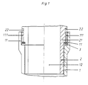
- Fig. 1 the partial section shows the lower foot part 1 and the upper foot part 2 in the area of the telescopic movement possibility.
- the lower foot part 1 is shown without the stand area, which corresponds to that of the prior art.
- ledge-like projections 111 protrude from the wall areas 11 which are slightly bent outwards and run into the hollow interior 12 opposite.
- These strip-like projections 111 engage in receiving grooves 22 which are introduced longitudinally on the associated outer wall regions 21 of the upper foot part 2.
- the upper part 2 of the foot can be adjusted in its displacement height in the lower part 1 by means of prefabricated spacer elements 3.
- These spacer elements 3 can be strip-shaped supports of a predetermined thickness, which can have corresponding recesses in the area of the strip-like projections 111 of the lower foot part 1.
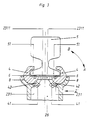
- Fig. 2 shows the section through the busbar bracket with the two converging wall areas inclined to each other in the closed position.
- the left free wall area 23 is shown in a partial section at the upper free end of the upper foot part 2, while the wall area 24 which is inclined in a converging manner is only slightly cut by the partial section shown.
- the wall regions 23, 24 which are inclined in a converging manner are supported in the region of their meeting by a central wall 25 of the upper foot part 2.
- the wall area 23 is cut exactly in the area of the keyhole-shaped opening 231.
- the mushroom-shaped projection of the claw-like receiving element 4 engages through the keyhole-shaped opening.
- the mushroom-shaped projection of the claw-like receiving element 4 consists of the larger-diameter head region 41 and the smaller-diameter guide region 42.
- the larger-diameter head region 41 is inserted through the larger circumferential opening 2311 of the keyhole-shaped opening 231 and is also used its guide area 42 shows the slit opening 2312 with a smaller diameter.
- the head region 41 of the mushroom-shaped projection engages behind the smaller-diameter slot opening 2312 of the keyhole-shaped opening 231.
- the claws 43 overlap the holding areas 51 of the busbar 5.
- the holding areas 51 of the busbar 5 rest on slide rails 6 which are embedded in the claw-like receiving elements 4.
- the claw-like receiving elements 4 are guided against lateral displacement in bead-like elevations 7 on the wall regions 23, 24 which are inclined in a converging manner at the free end of the upper part 2 of the foot.
- the claw-like receiving elements 4 Due to the weight of the busbar, which is usually made of steel, the claw-like receiving elements 4 have moved downward from the position shown in FIG. 2a on the wall regions 23, 24 which are inclined convergingly, so that the busbar 5 thereby locked in its end position. A self-locking and self-holding of the busbar 5 is ensured by the downward sloping surfaces of the mutually inclined wall regions 23, 24.
- Fig. 3 shows a partial section through the busbar holder with roller-shaped holding bodies.
- open, semicircular receptacles 8 are inserted at the free end of the upper part 2 of the foot.
- These semicircular receptacles 8 have keyhole-shaped openings 231 directed towards the inner cavity 26 of the foot upper part 2 for the engagement of mushroom-shaped projections, which also consist of the head region 41 and the guide region 42 and are arranged on the claw-like receiving elements 4.
- the claw-like receiving elements 4 are roller-shaped holding bodies which can be pivoted in the direction of the arrow over the length of the keyhole-shaped openings 231.
- the pivoting of the claw-like receiving elements 4 in the direction of arrow A means the opening of the holding bodies for receiving the busbar foot 51.
- the pivoting of the holding bodies in the direction of arrow B means the closing and fixing of the busbar 5 within the holding bodies.
- the roller-shaped holding bodies - claw-like receiving elements 4 - in FIG. 3 are locked in the same way via the mushroom-shaped projections 41, 42 and the keyhole-shaped openings 231, 2311, 2312, as described for FIG. 2.
Landscapes
- Engineering & Computer Science (AREA)
- Mechanical Engineering (AREA)
- Architecture (AREA)
- Civil Engineering (AREA)
- Structural Engineering (AREA)
- Installation Of Bus-Bars (AREA)
- Installation Of Indoor Wiring (AREA)
- Insulators (AREA)
Claims (9)
- Support isolant de rail conducteur utilisé dans des systèmes de circulation, comportant un élément de pied porteur et une zone disposée à sa partie supérieure libre destinée à recevoir le pied du rail conducteur, caractérisé par le fait que l'élément de pied porteur (1) est constitué d'une partie inférieure du pied creuse et d'une partie supérieure du pied (2) qui peut y coulisser de manière télescopique et qu'à l'extrémité de la partie libre de la partie supérieure du pied (2) sont disposés des pattes de réception (4) qui, sous l'effet de la pression d'appui du rail conducteur (5) utilisé, parviennent d'une position de chargement ouverte à une position de maintien enserrant le pied (51) du rail conducteur (5).
- Support isolant selon la revendication 1, caractérisé par le fait qu'à partir des zones de parois (11) de la partie inférieure du pied (1), des épaulements opposés en forme de nervure (111) pénètrent dans l'espace intérieur creux (12) et prennent dans des rainures de réception longitudinales prévues dans les zones correspondantes de la paroi extérieure (21) de la partie supérieure du pied (2).
- Support isolant selon les revendications 1 et 2, caractérisé par le fait que la partie supérieure du pied (2) est réglable en hauteur dans la partie inférieure du pied (1) à l'aide d'éléments d'écartement préfabriqués (3).
- Support isolant selon la revendication 1, caractérisé par le fait que l'extrémité libre de la partie supérieure du pied (2) est constituée de deux zones de parois (23, 24) inclinées convergentes, qui sont supportées en outre par une paroi médiane (25) de la partie supérieure du pied (2) dans leur zone de contact et qui présentent des trous débouchants médians (231) en forme de trous de serrures destinés à recevoir les épaulements (41, 42) en forme de champignons des pattes de réception (4).
- Support isolant selon la revendication 1, caractérisé par le fait que les pattes de réception (4) sont des pièces moulées recouvrant l'extrémité libre de la partie supérieure du pied (2) et que ces piéces moulées présentent des rainures de guidage dans leur face inférieure plane dans lesquelles prennent des étriers de guidage (7) élastiques en saillie par dessus les zones de parois (23, 24) de l'extrémité libre de la partie supérieure du pied (2).
- Support isolant selon la revendication 4, caractérisé par le fait que la forme de la plus grande section (2311) des ouvertures en forme de trous de serrures (231) épouse les bords supérieurs des zones de parois (23, 24) inclinées et convergentes.
- Support isolant selon la revendication 1, caractérisé par le fait que des logements demi-circulaires (8) opposés, ouverts vers le haut, sont creusés dans l'extrémité libre de la partie supérieure du pied (2) et présentent, aux pattes de réception (4), des ouvertures en forme de trous de serrures (231), dirigées vers l'espace intérieur creux (25) de la partie supérieure du pied (2) et destinées à recevoir des épaulements en forme de champignons (41, 42).
- Support isolant selon la revendication 7, caractérisé par le fait que les pattes de réception (4) sont des pièces de maintien cylindiques.
- Support isolant selon la revendication 7, caractérisé par le fait que la plus grande section (2311) des ouvertures en forme de trous de serrures (231) est creusée dans les logements semi-circulaires (8) de la face avant de la partie supérieure du pied (2).
Applications Claiming Priority (2)
| Application Number | Priority Date | Filing Date | Title |
|---|---|---|---|
| DE9112844U DE9112844U1 (de) | 1991-10-16 | 1991-10-16 | Isolationsträger für Stromschienen |
| DE9112844U | 1991-10-16 |
Publications (2)
| Publication Number | Publication Date |
|---|---|
| EP0537472A1 EP0537472A1 (fr) | 1993-04-21 |
| EP0537472B1 true EP0537472B1 (fr) | 1994-03-09 |
Family
ID=6872290
Family Applications (1)
| Application Number | Title | Priority Date | Filing Date |
|---|---|---|---|
| EP92115334A Expired - Lifetime EP0537472B1 (fr) | 1991-10-16 | 1992-09-05 | Support d'isolation pour barres conductrices |
Country Status (3)
| Country | Link |
|---|---|
| EP (1) | EP0537472B1 (fr) |
| DE (2) | DE9112844U1 (fr) |
| ES (1) | ES2051141T3 (fr) |
Families Citing this family (1)
| Publication number | Priority date | Publication date | Assignee | Title |
|---|---|---|---|---|
| GB9200024D0 (en) * | 1992-01-02 | 1992-02-26 | Rehau Ag & Co | Electrical insulator |
Family Cites Families (2)
| Publication number | Priority date | Publication date | Assignee | Title |
|---|---|---|---|---|
| US1632662A (en) * | 1926-05-24 | 1927-06-14 | Michalek George | Rail support |
| DE1615545C3 (de) * | 1968-02-01 | 1974-02-14 | Licentia Patent-Verwaltungs-Gmbh, 6000 Frankfurt | Stromschienenträger |
-
1991
- 1991-10-16 DE DE9112844U patent/DE9112844U1/de not_active Expired - Lifetime
-
1992
- 1992-09-05 EP EP92115334A patent/EP0537472B1/fr not_active Expired - Lifetime
- 1992-09-05 DE DE92115334T patent/DE59200084D1/de not_active Expired - Fee Related
- 1992-09-05 ES ES92115334T patent/ES2051141T3/es not_active Expired - Lifetime
Also Published As
| Publication number | Publication date |
|---|---|
| DE59200084D1 (de) | 1994-04-14 |
| DE9112844U1 (de) | 1991-11-28 |
| ES2051141T3 (es) | 1994-06-01 |
| EP0537472A1 (fr) | 1993-04-21 |
Similar Documents
| Publication | Publication Date | Title |
|---|---|---|
| EP0935076B1 (fr) | Dispositif de fixation pour fixer plusieurs ferrures de meuble à un élément de meuble | |
| DE2708167A1 (de) | Schublade aus kunststoff | |
| EP0865132A1 (fr) | Dispositif de fixation de barres omnibus sur un rail support | |
| DE3535961A1 (de) | Scharnier | |
| DE1923669A1 (de) | Verankerungsvorrichtung zum loesbaren Befestigen von Gegenstaenden an einer Hohlprofilschiene | |
| EP0537472B1 (fr) | Support d'isolation pour barres conductrices | |
| DE10065962A1 (de) | Metallprofil für Strassenmöbelkonstruktionen | |
| DE8806387U1 (de) | Installationsträger für Stromschienen | |
| WO2000040874A1 (fr) | Canal de guidage | |
| DE19921212B4 (de) | Stulpschienenbeschlag für ein Fenster, eine Tür o. dgl. | |
| DE3247506C2 (de) | Gasdichte Unterdecke | |
| DE2641606C2 (de) | Wandkonstruktion für Kabinen, insbesondere für Sanitärkabinen | |
| DE19719013C2 (de) | Mit einem Wandhalter versehenes, im Querschnitt U-förmiges Halteprofil für eine Trennwand | |
| EP0141212B1 (fr) | Rail pour monorail de voie à suspension | |
| DE19742095C1 (de) | Anordnung zur schraubenlosen Verbindung von Gitterkabelbahnen | |
| CH482929A (de) | Verankerungsvorrichtung zum lösbaren Befestigen von Gegenständen an einer Hohlprofilschiene | |
| CH553951A (de) | Klemmbuegel zum fixieren der rohrschlangen einer fussbodenheizung. | |
| DE19620709C1 (de) | Möbelfußsystem | |
| DE19742780A1 (de) | Laufrollen- und Führungsanordnung für Schiebetüren | |
| DE2854453C2 (de) | Skiträger für Kraftfahrzeuge | |
| DE29908332U1 (de) | Aufhängevorrichtung für eine Schiebetür | |
| DE7534438U (de) | Tuerschiene fuer einen ganzglastuerfluegel | |
| DE2363298A1 (de) | Auf- und abrollbarer vorhang | |
| DE7735042U1 (de) | Liegemoebel-gestell mit querlatten | |
| DE1293182B (de) | Haltevorrichtung fuer Stromschienen mit seitlichen Laengsnuten |
Legal Events
| Date | Code | Title | Description |
|---|---|---|---|
| PUAI | Public reference made under article 153(3) epc to a published international application that has entered the european phase |
Free format text: ORIGINAL CODE: 0009012 |
|
| 17P | Request for examination filed |
Effective date: 19920905 |
|
| AK | Designated contracting states |
Kind code of ref document: A1 Designated state(s): DE ES FR GB GR IT |
|
| 17Q | First examination report despatched |
Effective date: 19930726 |
|
| GRAA | (expected) grant |
Free format text: ORIGINAL CODE: 0009210 |
|
| AK | Designated contracting states |
Kind code of ref document: B1 Designated state(s): DE ES FR GB GR IT |
|
| ITF | It: translation for a ep patent filed | ||
| REF | Corresponds to: |
Ref document number: 59200084 Country of ref document: DE Date of ref document: 19940414 |
|
| GBT | Gb: translation of ep patent filed (gb section 77(6)(a)/1977) |
Effective date: 19940415 |
|
| REG | Reference to a national code |
Ref country code: ES Ref legal event code: FG2A Ref document number: 2051141 Country of ref document: ES Kind code of ref document: T3 |
|
| REG | Reference to a national code |
Ref country code: GR Ref legal event code: FG4A Free format text: 3011555 |
|
| ET | Fr: translation filed | ||
| PLBE | No opposition filed within time limit |
Free format text: ORIGINAL CODE: 0009261 |
|
| 26N | No opposition filed | ||
| PGFP | Annual fee paid to national office [announced via postgrant information from national office to epo] |
Ref country code: FR Payment date: 19960819 Year of fee payment: 5 |
|
| PGFP | Annual fee paid to national office [announced via postgrant information from national office to epo] |
Ref country code: ES Payment date: 19960916 Year of fee payment: 5 |
|
| PGFP | Annual fee paid to national office [announced via postgrant information from national office to epo] |
Ref country code: GB Payment date: 19961204 Year of fee payment: 5 |
|
| PGFP | Annual fee paid to national office [announced via postgrant information from national office to epo] |
Ref country code: GR Payment date: 19970709 Year of fee payment: 6 |
|
| PGFP | Annual fee paid to national office [announced via postgrant information from national office to epo] |
Ref country code: DE Payment date: 19970805 Year of fee payment: 6 |
|
| PG25 | Lapsed in a contracting state [announced via postgrant information from national office to epo] |
Ref country code: GB Free format text: LAPSE BECAUSE OF NON-PAYMENT OF DUE FEES Effective date: 19970905 |
|
| PG25 | Lapsed in a contracting state [announced via postgrant information from national office to epo] |
Ref country code: ES Free format text: LAPSE BECAUSE OF NON-PAYMENT OF DUE FEES Effective date: 19970906 |
|
| PG25 | Lapsed in a contracting state [announced via postgrant information from national office to epo] |
Ref country code: GR Free format text: LAPSE BECAUSE OF NON-PAYMENT OF DUE FEES Effective date: 19970930 Ref country code: FR Free format text: THE PATENT HAS BEEN ANNULLED BY A DECISION OF A NATIONAL AUTHORITY Effective date: 19970930 |
|
| GBPC | Gb: european patent ceased through non-payment of renewal fee |
Effective date: 19970905 |
|
| REG | Reference to a national code |
Ref country code: FR Ref legal event code: ST |
|
| PG25 | Lapsed in a contracting state [announced via postgrant information from national office to epo] |
Ref country code: DE Free format text: LAPSE BECAUSE OF NON-PAYMENT OF DUE FEES Effective date: 19990701 |
|
| REG | Reference to a national code |
Ref country code: ES Ref legal event code: FD2A Effective date: 19981013 |
|
| PG25 | Lapsed in a contracting state [announced via postgrant information from national office to epo] |
Ref country code: IT Free format text: LAPSE BECAUSE OF NON-PAYMENT OF DUE FEES Effective date: 20050905 |