EP0535685B1 - Method for manufacturing a liquid jet recording head - Google Patents
Method for manufacturing a liquid jet recording head Download PDFInfo
- Publication number
- EP0535685B1 EP0535685B1 EP92116853A EP92116853A EP0535685B1 EP 0535685 B1 EP0535685 B1 EP 0535685B1 EP 92116853 A EP92116853 A EP 92116853A EP 92116853 A EP92116853 A EP 92116853A EP 0535685 B1 EP0535685 B1 EP 0535685B1
- Authority
- EP
- European Patent Office
- Prior art keywords
- liquid
- recording head
- jet recording
- ink
- polishing
- Prior art date
- Legal status (The legal status is an assumption and is not a legal conclusion. Google has not performed a legal analysis and makes no representation as to the accuracy of the status listed.)
- Expired - Lifetime
Links
- 239000007788 liquid Substances 0.000 title claims abstract description 93
- 238000000034 method Methods 0.000 title claims abstract description 23
- 238000004519 manufacturing process Methods 0.000 title claims abstract description 17
- 238000005498 polishing Methods 0.000 claims abstract description 36
- 239000000463 material Substances 0.000 claims description 23
- 238000005520 cutting process Methods 0.000 claims description 19
- 229920005989 resin Polymers 0.000 claims description 10
- 239000011347 resin Substances 0.000 claims description 10
- 239000000758 substrate Substances 0.000 claims description 10
- 238000007599 discharging Methods 0.000 claims description 4
- 239000003566 sealing material Substances 0.000 claims 2
- 239000000945 filler Substances 0.000 abstract description 15
- 239000010410 layer Substances 0.000 description 46
- 239000007787 solid Substances 0.000 description 40
- 235000019589 hardness Nutrition 0.000 description 15
- HEMHJVSKTPXQMS-UHFFFAOYSA-M Sodium hydroxide Chemical compound [OH-].[Na+] HEMHJVSKTPXQMS-UHFFFAOYSA-M 0.000 description 12
- 238000000429 assembly Methods 0.000 description 11
- 238000011084 recovery Methods 0.000 description 11
- 238000006243 chemical reaction Methods 0.000 description 8
- 229910003460 diamond Inorganic materials 0.000 description 7
- 239000010432 diamond Substances 0.000 description 7
- XEKOWRVHYACXOJ-UHFFFAOYSA-N Ethyl acetate Chemical compound CCOC(C)=O XEKOWRVHYACXOJ-UHFFFAOYSA-N 0.000 description 6
- 230000000694 effects Effects 0.000 description 6
- 150000001875 compounds Chemical class 0.000 description 5
- 238000012360 testing method Methods 0.000 description 5
- 238000007796 conventional method Methods 0.000 description 4
- 239000002245 particle Substances 0.000 description 4
- 230000004044 response Effects 0.000 description 4
- 235000011121 sodium hydroxide Nutrition 0.000 description 4
- 239000002904 solvent Substances 0.000 description 4
- 238000001029 thermal curing Methods 0.000 description 4
- VYPSYNLAJGMNEJ-UHFFFAOYSA-N Silicium dioxide Chemical compound O=[Si]=O VYPSYNLAJGMNEJ-UHFFFAOYSA-N 0.000 description 3
- 238000009835 boiling Methods 0.000 description 3
- 239000011521 glass Substances 0.000 description 3
- 238000010438 heat treatment Methods 0.000 description 3
- 230000005540 biological transmission Effects 0.000 description 2
- 229910000420 cerium oxide Inorganic materials 0.000 description 2
- 239000003086 colorant Substances 0.000 description 2
- 230000008602 contraction Effects 0.000 description 2
- 238000001723 curing Methods 0.000 description 2
- 239000003822 epoxy resin Substances 0.000 description 2
- 238000003754 machining Methods 0.000 description 2
- 230000007246 mechanism Effects 0.000 description 2
- BMMGVYCKOGBVEV-UHFFFAOYSA-N oxo(oxoceriooxy)cerium Chemical compound [Ce]=O.O=[Ce]=O BMMGVYCKOGBVEV-UHFFFAOYSA-N 0.000 description 2
- 229920000647 polyepoxide Polymers 0.000 description 2
- 239000004925 Acrylic resin Substances 0.000 description 1
- 229920000178 Acrylic resin Polymers 0.000 description 1
- BVKZGUZCCUSVTD-UHFFFAOYSA-L Carbonate Chemical compound [O-]C([O-])=O BVKZGUZCCUSVTD-UHFFFAOYSA-L 0.000 description 1
- 239000004640 Melamine resin Substances 0.000 description 1
- 229920000877 Melamine resin Polymers 0.000 description 1
- 229920001807 Urea-formaldehyde Polymers 0.000 description 1
- -1 acryl Chemical group 0.000 description 1
- 239000012790 adhesive layer Substances 0.000 description 1
- 230000015572 biosynthetic process Effects 0.000 description 1
- 238000010538 cationic polymerization reaction Methods 0.000 description 1
- 230000008859 change Effects 0.000 description 1
- 239000003795 chemical substances by application Substances 0.000 description 1
- 238000004140 cleaning Methods 0.000 description 1
- 239000008119 colloidal silica Substances 0.000 description 1
- 238000000151 deposition Methods 0.000 description 1
- 230000002542 deteriorative effect Effects 0.000 description 1
- 239000003814 drug Substances 0.000 description 1
- 238000005530 etching Methods 0.000 description 1
- 238000001704 evaporation Methods 0.000 description 1
- 230000008020 evaporation Effects 0.000 description 1
- 230000001747 exhibiting effect Effects 0.000 description 1
- 239000010419 fine particle Substances 0.000 description 1
- 238000011835 investigation Methods 0.000 description 1
- 230000005499 meniscus Effects 0.000 description 1
- 230000004048 modification Effects 0.000 description 1
- 238000012986 modification Methods 0.000 description 1
- 238000000059 patterning Methods 0.000 description 1
- 239000005011 phenolic resin Substances 0.000 description 1
- 150000004291 polyenes Chemical class 0.000 description 1
- 229920001721 polyimide Polymers 0.000 description 1
- 239000009719 polyimide resin Substances 0.000 description 1
- 229920000642 polymer Polymers 0.000 description 1
- 238000006116 polymerization reaction Methods 0.000 description 1
- 229920006295 polythiol Polymers 0.000 description 1
- 229920002635 polyurethane Polymers 0.000 description 1
- 239000004814 polyurethane Substances 0.000 description 1
- 229920005749 polyurethane resin Polymers 0.000 description 1
- 239000000843 powder Substances 0.000 description 1
- 230000008569 process Effects 0.000 description 1
- 238000010526 radical polymerization reaction Methods 0.000 description 1
- 239000004065 semiconductor Substances 0.000 description 1
- 239000000377 silicon dioxide Substances 0.000 description 1
- 229920002379 silicone rubber Polymers 0.000 description 1
- 239000004945 silicone rubber Substances 0.000 description 1
- 229920006337 unsaturated polyester resin Polymers 0.000 description 1
- XLYOFNOQVPJJNP-UHFFFAOYSA-N water Substances O XLYOFNOQVPJJNP-UHFFFAOYSA-N 0.000 description 1
Images


Classifications
-
- B—PERFORMING OPERATIONS; TRANSPORTING
- B41—PRINTING; LINING MACHINES; TYPEWRITERS; STAMPS
- B41J—TYPEWRITERS; SELECTIVE PRINTING MECHANISMS, i.e. MECHANISMS PRINTING OTHERWISE THAN FROM A FORME; CORRECTION OF TYPOGRAPHICAL ERRORS
- B41J2/00—Typewriters or selective printing mechanisms characterised by the printing or marking process for which they are designed
- B41J2/005—Typewriters or selective printing mechanisms characterised by the printing or marking process for which they are designed characterised by bringing liquid or particles selectively into contact with a printing material
- B41J2/01—Ink jet
- B41J2/135—Nozzles
- B41J2/16—Production of nozzles
- B41J2/1621—Manufacturing processes
- B41J2/1632—Manufacturing processes machining
-
- B—PERFORMING OPERATIONS; TRANSPORTING
- B41—PRINTING; LINING MACHINES; TYPEWRITERS; STAMPS
- B41J—TYPEWRITERS; SELECTIVE PRINTING MECHANISMS, i.e. MECHANISMS PRINTING OTHERWISE THAN FROM A FORME; CORRECTION OF TYPOGRAPHICAL ERRORS
- B41J2/00—Typewriters or selective printing mechanisms characterised by the printing or marking process for which they are designed
- B41J2/005—Typewriters or selective printing mechanisms characterised by the printing or marking process for which they are designed characterised by bringing liquid or particles selectively into contact with a printing material
- B41J2/01—Ink jet
- B41J2/135—Nozzles
- B41J2/16—Production of nozzles
- B41J2/1601—Production of bubble jet print heads
- B41J2/1604—Production of bubble jet print heads of the edge shooter type
Definitions
- the present invention relates to a liquid jet recording head for used with an ink jet recording system to generate small recording liquid droplets, a method for manufacturing such a recording head, and a recording apparatus having such a recording head.
- Liquid jet recording heads used with ink jet recording systems generally comprise small recording liquid discharge openings, liquid passages, and liquid discharging energy generating portions disposed in the liquid passages.
- An example of a method for manufacturing such conventional liquid jet recording heads is disclosed in the Japanese Patent Application Laid-open No. 57-43876.
- a photosensitive compound layer for example, negative type dry film LAMINAR (manufactured by DYNA CHEMICAL Co.), SR-1000G-50 (manufactured by HITACHI KASEI Co., Ltd.), SR-1000N (manufactured by HITACHI KASEI Co., Ltd) or the like
- a photosensitive compound layer for example, negative type dry film LAMINAR (manufactured by DYNA CHEMICAL Co.), SR-1000G-50 (manufactured by HITACHI KASEI Co., Ltd.), SR-1000N (manufactured by HITACHI KASEI Co., Ltd) or the like
- ink liquid passages also referred to as "nozzles" hereinafter
- a liquid chamber forming member (lid plate) is bonded to the surface of the substrate via an adhesive layer to form two pairs of liquid jet recording heads. Thereafter, the assembly is cut by a diamond blade to separate two pairs of heads and at the same time to form liquid discharge openings, thereby obtaining individual liquid jet recording heads. According to this conventional method, it is possible to form the liquid passages very uniformly and to manufacture the heads in great quantities, since the photolithographic technique can be used.
- a solid layer is deposited on a substrate at locations where nozzles are to be formed, and the solid layer is covered by a layer made of active energy ray curable material (nozzle forming material) and then a liquid chamber forming member is arranged on such layer. Then, the active energy ray curable material is cured by the active energy rays. Thereafter, the assembly is cut by a diamond blade at a high speed to separate two pairs of heads. Then, a discharge opening surface is polished to remove the chipping generated during the cutting operation, thereby finishing the discharge opening surface. Finally, by dissolving the solid layer by a removing liquid to remove the solid layer, thereby forming the nozzles.
- An object of the present invention is to provide a unique method for manufacturing a liquid jet recording head, which can eliminate the above-mentioned conventional drawbacks and which is particularly effective in the manufacture of a liquid jet recording head of high density multi-array type.
- the present invention was created on the basis of the following knowledge.
- the inventors found that the chipping areas (broken portions) which generated during the polishing operation of the discharge opening surface were concentrated at the edges of the discharge openings. Since the solid layer has relatively low hardness (softer), it is considered that the foreign matters enter into the solid layer during the polishing operation to interfere with the edges of the discharge openings, thereby occurring the chipping. It is assumed that the reason why this fact was not remarked conventionally is that, since the solid layer provided in correspondence to the ink passages was to be finally removed in the liquid jet recording head, a softer solid layer (easy to remove) was preferable as long as it could ensure the dimension and configuration of the ink passages precisely.
- the inventors found that the edges of the discharge openings having substantially no chipping could be obtained by increasing the hardness of the solid layer by curing the solid layer in correspondence to the ink passages to prevent the foreign matters from entering into the solid layer.
- the inventors found that when the solid layer had the pencil hardness of H or more, preferably 2H or more, and more preferably 3H or more, the above effect could be satisfactorily obtained.
- the pencil hardness is based on the test pencil hardness defined by the Japanese Industrial Standard K5400-6:14(3), and the test machine was in accordance with the Japanese Industrial Standard K5401. The testing method was in accordance with the Japanese Industrial Standard K6894.
- Fig. 5 is a perspective view of an ink jet recording head which comprises heating portions 1103 of electro-thermal converters formed on a substrate 1102 by a film forming technique via a semi-conductor process such as the etching, depositing, spattering and the like, electrodes 1104, liquid passage defining walls 1105, and a lid plate 1106.
- Recording liquid 1112 is supplied from a liquid reservoir (not shown) to a common liquid chamber 1108 of the recording head 1101 via a liquid supply tube 1107.
- the reference numeral 1109 denotes a liquid supply tube connector.
- the liquid 1112 supplied to the common liquid chamber 1108 is supplied to liquid passages 1110 by a so-called capillary phenomenon, and constitutes meniscuses at discharge openings positioned at free ends of the liquid passages.
- the liquid portions on the heat generating portions 1103 are rapidly heated to form bubbles in the liquid passages.
- the liquid is discharged from the corresponding discharge opening 1111 as a liquid droplet.
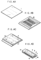
- FIGs. 3A - 3F are schematic perspective views showing steps of a method for manufacturing a liquid jet recording head according to an embodiment of the present invention.
- a solid layer 8 made of positive type photosensitive resin, for example, is formed on a substrate 1 on which a plurality of energy generating bodies are arranged, in such a manner that the solid layer covers the energy generating bodies (see Fig. 3A).
- a liquid passage wall forming layer 2 is laminated on the solid layer 8 to cover the latter (see Fig. 3B).
- a light permeable lid plate 4 having liquid supply openings is laminated on the layer 2 (see Fig. 3C).
- a portion corresponding to the common liquid chamber is masked, and the exposure is effected from a direction shown by the arrows to make the solid layer 8 soluble in a solvent.
- the sub-assembly is cut along the line A - A' at a discharge opening forming portion (see Fig. 3D).
- the solvent is circulated via the liquid supply openings 6 (to the common chamber 9) as shown in the arrows 110, thereby dissolving the solid layer 8 and removing the latter (see Fig. 3E).
- the discharge opening forming portion is polished to form the discharge openings (see Fig. 3F).
- the solid layer in the recording head sub-assembly so formed is cured by thermal curing technique and the like up to the pencil hardness H or more, before the polishing operation.
- the substrate used in the present invention is preferably made of glass, silica or the like, so that the heads can be manufactured in great quantities and the smoothness of surface can easily be achieved.
- the solid layer is preferably made of any material which permits the patterning of the liquid passage configuration and has the water-resistance property and which is easy to be dissolved and removed. More specifically, the solid layer may be made of resin material such as positive type dry film, positive type liquid resist or the like.
- the liquid passage wall forming material is preferably ultraviolet ray curable material in consideration of the mass-production of the heads, and, more particularly, it may be epoxy resin, acrylic resin, diglycol-dialkyl carbonate resin, unsaturated polyester resin, polyurethane resin, polyimide resin, melamine resin, phenol resin, urea resin or the like.
- epoxy resin which can initiate the cationic polymerization by light acryl oligomers having acrylester group which permits the radical polymerization by light, photopolymerization resin including polythiol and polyene * including much vinyle radical, and unsaturated cycloacetal resin are suitable for the constructural material because they have the faster polymerization speed and provide the stable polymer.
- the lid plate is preferably made of glass, particularly, for example, Pilex 7059 (trade mark, Corning Co.) or Tenpax (trade mark, Shot Co.) because they are permeable to active energy rays such as ultraviolet rays and have good anti-medicine property.
- polishing material used in the polishing operation is preferably ones used to polish the glass. More specifically, ROX-FP (trade mark, TOHOKU KINZOKU Co. in Japan) or ROM-M3 (trade mark, TOHOKU KINZOKU Co.) having cerium oxide as a main component is preferable. Such polishing material is dissolved in water to form polishing liquid.
- the polishing material or agent has fine particles having a diameter of about 1 - 2 ⁇ m, which particles are condensed under the dry condition to provide the firm cohesion.
- polisher used in the polishing operation is preferably polyurethane in consideration of the durability.
- the solid layer removing liquid used after the polishing operation is preferably caustic soda, ethyl acetate solvent or the like. Incidentally, it should be noted that the present invention is not limited to the above-mentioned materials.
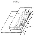
- Fig. 1 is a perspective view of a recording head sub-assembly showing a cross-section or cut surface after the cutting operation.
- the polishing particles are very small as mentioned above and the polisher acting as the polishing surface serves also as a buffer, the polishing particles themselves do not cause the chipping.
- the chipping is apt to occur frequently. Such foreign matters 10 reach around the discharge opening from various directions during the polishing operation. This is inevitable in the polishing operation.
- the solid layer 8 is extremely soft as in the conventional case, after the foreign matters penetrate into the solid layer 8, they are caught by the edges of the discharge openings in the lid plate and/or the liquid passage wall forming material layer, thus causing the chipping.
- the solid layer is thermally cured before the polishing operation.
- This thermal curing operation may be effected before or after the cutting operation.
- a machining operation may be effected as an intermediate step.
- the solid layer has the hardness greater than the pencil hardness H and the water-resistance property. Accordingly, the foreign matters cannot penetrate into the solid layer from the discharge openings, thus preventing the chipping. Further, since the cured solid layer can be easily removed by caustic soda or ethyl acetate solvent in the later step, the problem regarding the residual matters in the liquid passage formation can be solved.
- a photosensitive compound layer 16 is formed on the substrate 1, and then the liquid passages are formed, and thereafter, a lid plate 4 is laminated on the compound layer 16.
- the cutting, thermal curing, polishing and filler removing operations are effected successively.
- the filler may be loaded after the cutting operation.
- the filler is preferably positive type resist, and the thermal curing may be effected for 10 - 20 minutes under the temperature of 130°C. Since the steps other than the filler loading step are the same as those in the previous embodiment, the explanation of such steps will be omitted.
- an excellent effect can be obtained in a recording head and a recording apparatus of a type among the ink jet recording apparatuses, in which ink is discharged by utilizing thermal energy to form ink droplets.
- an electro-thermal conversion member disposed to align to a sheet or a liquid passage in which liquid (ink) is held is supplied with at least one drive signal which corresponds to information to be recorded and which enables the temperature of the electrothermal conversion member to be raised higher than a nuclear boiling point, so that thermal energy is generated in the electro-thermal conversion member and film boiling is caused to take place on the surface of the recording head which is heated.
- this system is particularly suitable for the On-Demand type recording method.
- liquid (ink) Due to the enlargement and contraction of the bubble, liquid (ink) is discharged through the discharge opening or port, so that at least one liquid droplet is formed.
- the aforesaid drive signal is made to be a pulse signal, a further satisfactory effect can be obtained in that the bubble can immediately and properly be enlarged/contracted and liquid (ink) can be discharged while exhibiting excellent responsibility.
- a further excellent recording operation can be performed.
- a structure disclosed in U.S. Patent Nos. 4,558,333 and 4,459,600 in which the heated portion is disposed in a bent portion is included in the scope of the present invention.
- the present invention can effectively be embodied in a structure in which a common slit is made to be the discharge portion of a plurality of electro-thermal conversion members and which is disclosed in the Japanese Patent Laid-open Appln. No. 59-123670 and a structure in which an opening for absorbing thermal pressure wave is formed to align to the discharge port and which is disclosed in the Japanese Patent Appln. Laid-open No. 59-138461.
- a full line type recording head having a length which corresponds to the width of the maximum recording medium which can be recorded by the recording apparatus may be a structure capable of realizing the aforesaid length and formed by combining a plurality of recording heads as disclosed in the aforesaid specifications or a structure formed by an integrally formed recording head.
- the present invention will enable the aforesaid effects to be exhibited further effectively.
- the present invention can also be effectively adapted to a structure having an interchangeable chip type recording head which can be electrically connected to the body of the apparatus or to which ink can be supplied from the body of the apparatus when it is mounted on the body of the apparatus or a carriage type recording head integrally formed to the recording head.
- the recording head recovery means and an auxiliary means of the recording apparatus it is preferable to additionally provide the recording head recovery means and an auxiliary means of the recording apparatus according to the present invention because the effect of the present invention can further be stabled. Specifically, an effect can be stably performed by providing a recording head capping means, a cleaning means, a pressurizing or sucking means, an electro-thermal conversion member or another heating device or an auxiliary heating means formed by combining the aforesaid elements and by performing a previous discharge mode in which a discharge is performed individually from the recording operation.
- the recording mode of the recording apparatus may be a recording mode for recording only main color such as black and a structure may be that formed by integrally forming recording heads or a structure formed by combining a plurality of recording heads.
- the present invention can significantly effectively be adapted to an apparatus having a recording head of a plurality of colors or at least one full color head arranged to mix colors.
- liquid ink ink which is solid at room temperature or ink which is softened at room temperature may be used.
- the temperature of the ink is usually controlled in a range from 30°C to 70°C to make the viscosity of ink to be in a stable discharge range or an ink which is liquefied in response to a record signal supplied may be used.
- ink temperature rise of which is prevented by positively using the temperature rise due to the thermal energy as energy of state change from the solid state to the liquid state of ink or ink which is solidified when it is allowed to stand in order to prevent the evaporation of ink may be used. That is, ink which is liquefied by thermal energy such as ink liquefied by thermal energy supplied in response to the record signal and discharged as ink droplet or ink which is solidified when it reaches the recording medium can be employed in the present invention.
- ink may be, in the form of liquid or solid, held by a recess of a porous sheet or a through hole (as disclosed in the Japanese Patent Laid-open Appln. Nos. 54-56847 and 60-71260) and disposed to confront the electro-thermal conversion member.
- ink be discharged by the aforesaid film boiling method.
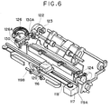
- Fig. 6 is a perspective view showing an example of an ink jet recording apparatus (IJRA) on which the recording head presented by the present invention is mounted as an ink jet head cartridge (IJC).
- IJRA ink jet recording apparatus
- IJC ink jet head cartridge
- an ink jet head cartridge (IJC) 120 having a group of nozzles for discharging ink onto a recording surface of a recording sheet rested on a platen 124.
- the ink jet head cartridge 120 is held by a carriage 116 which can be reciprocally shifted along the whole recordable area of the ink jet head cartridge 120 by connecting to a drive belt 118 for transmitting a driving force of a drive motor 117 to the cartridge and by slidably engaged by two guide shafts 119A, 119B.
- a recording head recovery device 126 is arranged at one of the margins of the shifting path of the ink jet head cartridge 120 to confront a home position, for example.
- the recovery device 126 is driven by a motor 122 via a transmission mechanism 123 to cap the ink jet head cartridge 120.
- ink is sucked by an appropriate suction means provided in the head recovery device 126 or ink is pressurized by an appropriate pressurizing means provided in an ink supply path communicating with the ink jet head cartridge 120 to positively discharge the ink from the discharge openings, thereby performing the discharge recovery treatment such as the removal of the viscous ink.
- the ink jet head cartridge can be protected by capping it with the recovery device after the recording operation has been finished.
- a wiping blade 130 made of silicone rubber is disposed on a side surface of the head recovery device 126.
- the wiping blade 130 is cantilevered by a blade holder 131A and is driven by the motor 122 and the transmission mechanism 123 as in the recovery device 126 to be engaged by the discharge opening surface of the ink jet head cartridge 120.
- the wiping blade 130 is protruded in the shifting path of the ink jet head cartridge 120, thus removing the ink droplets, moisture and/or dirt adhered to the discharge opening surface of the cartridge 120.
- each recording head sub-assembly for an liquid jet recording head (referred to merely as “recording head” hereinafter) to include 256 discharge openings were formed by the method shown in Fig. 3. Then, each recording head sub-assembly was cut by a diamond blade of about # 600 (having diamond diameter of 20 - 30 ⁇ m).
- the positive type dry films (trade name: OZATEC R225, made by Hexist Japan Co., Ltd.) as the solid layers in the sub-assemblies were thermally cured under the temperature of 130°C for 10 minutes (per first 10 sub-assemblies), 15 minutes (per second 10 sub-assemblies) and 20 minutes (per third 10 sub-assemblies), respectively. Thereafter, the hardness of the cured solid layers was measured, and it was found that the hardnesses of the cured solid layers of first, second and third groups were higher than the pencil hardness H, 2H and 3H, respectively. Then, the recording head sub-assemblies were polished in the following manner.
- Fig. 2 is an explanatory view for showing the polishing operation.
- the polishing device comprises a polisher 151 (trade name: KSP66, made by Kyushu Denki Co., Ltd.) formed on a surface of a base plate 150, and a ring 152 with a carrier 153 disposed on the polisher.
- the recording head sub-assembly after the cutting operation was installed within a window 156 of the carrier 153 in the ring 152 so that the discharge opening surface of the sub-assembly was contacted with the polisher 151 vertically.
- the sub-assembly was polished by rotating the ring 152 itself and revolving the base plate 150 too while pouring a polishing liquid 100 consisting of cerium oxide and colloidal silica.
- the polishing speed was a few microns ( ⁇ ) - a few tenth microns.
- the recording head sub-assembly was after the polishing operation washed in a bath filling of caustic soda as the solid layer removing liquid, thereby removing the solid layer.
- a bath filling of caustic soda as the solid layer removing liquid thereby removing the solid layer.
- thirty liquid jet recording heads having no chipping could be obtained. Incidentally, it was found that the image quality obtained by such recording heads was very excellent.
- thirty sub-assemblies for an liquid jet recording head to include 256 discharge openings were formed by the method shown in Fig. 4.
- the positive type resist (trade name: AZ4903, made by Hexist Japan Co., Ltd.) as a filler was loaded in the liquid passages of each recording head sub-assembly.
- the fillers were thermally cured under the temperature of 130°C for 10 minutes (per first 10 sub-assemblies), 15 minutes (per second 10 sub-assemblies) and 20 minutes (per third 10 sub-assemblies), respectively. Thereafter, the hardness of the cured fillers was measured, and it was found that the hardnesses of the cured fillers of first, second and third groups were higher than the pencil hardness 1.3H, 2.5H and 3.6H, respectively.
- the recording head sub-assemblies were washed with caustic soda. As a result, thirty liquid jet recording heads having no chipping could be obtained. Incidentally, it was found that the image quality obtained by such recording heads was very excellent.
Landscapes
- Engineering & Computer Science (AREA)
- Manufacturing & Machinery (AREA)
- Particle Formation And Scattering Control In Inkjet Printers (AREA)
Applications Claiming Priority (2)
| Application Number | Priority Date | Filing Date | Title |
|---|---|---|---|
| JP256543/91 | 1991-10-03 | ||
| JP3256543A JPH0592570A (ja) | 1991-10-03 | 1991-10-03 | 液体噴射記録ヘツド、その製造方法、及び液体噴射記録ヘツドを備えた記録装置 |
Publications (3)
| Publication Number | Publication Date |
|---|---|
| EP0535685A2 EP0535685A2 (en) | 1993-04-07 |
| EP0535685A3 EP0535685A3 (en) | 1993-05-26 |
| EP0535685B1 true EP0535685B1 (en) | 1998-01-14 |
Family
ID=17294096
Family Applications (1)
| Application Number | Title | Priority Date | Filing Date |
|---|---|---|---|
| EP92116853A Expired - Lifetime EP0535685B1 (en) | 1991-10-03 | 1992-10-01 | Method for manufacturing a liquid jet recording head |
Country Status (5)
| Country | Link |
|---|---|
| US (1) | US6626521B1 (ja) |
| EP (1) | EP0535685B1 (ja) |
| JP (1) | JPH0592570A (ja) |
| AT (1) | ATE162137T1 (ja) |
| DE (1) | DE69224026T2 (ja) |
Families Citing this family (7)
| Publication number | Priority date | Publication date | Assignee | Title |
|---|---|---|---|---|
| US6164759A (en) * | 1990-09-21 | 2000-12-26 | Seiko Epson Corporation | Method for producing an electrostatic actuator and an inkjet head using it |
| US5365645A (en) * | 1993-03-19 | 1994-11-22 | Compaq Computer Corporation | Methods of fabricating a page wide piezoelectric ink jet printhead assembly |
| US5435060A (en) * | 1993-05-20 | 1995-07-25 | Compaq Computer Corporation | Method of manufacturing a single side drive system interconnectable ink jet printhead |
| EP0854040B1 (en) * | 1997-01-21 | 2003-03-19 | SCITEX DIGITAL PRINTING, Inc. | Method for providing particle-free ink jet printer components |
| DE10133939C2 (de) * | 2001-07-12 | 2003-11-06 | Tally Computerdrucker Gmbh | Verfahren zum Herstellen eines Tropfenerzeugers für Mikrotropfen, insbesondere eines Düsenkopfes für Tintendrucker und Tropfenerzeuger |
| EP1493570A4 (en) * | 2002-04-10 | 2007-03-14 | Sony Corp | LIQUID INJECTION HEAD, LIQUID INJECTION DEVICE, AND METHOD FOR MANUFACTURING LIQUID INJECTION HEAD |
| KR101054974B1 (ko) * | 2006-04-24 | 2011-08-05 | 캐논 가부시끼가이샤 | 잉크 제트 기록 헤드, 잉크 제트 카트리지, 및 잉크 제트 기록 헤드 제조 방법 |
Family Cites Families (20)
| Publication number | Priority date | Publication date | Assignee | Title |
|---|---|---|---|---|
| CA1127227A (en) | 1977-10-03 | 1982-07-06 | Ichiro Endo | Liquid jet recording process and apparatus therefor |
| US4330787A (en) | 1978-10-31 | 1982-05-18 | Canon Kabushiki Kaisha | Liquid jet recording device |
| US4345262A (en) | 1979-02-19 | 1982-08-17 | Canon Kabushiki Kaisha | Ink jet recording method |
| US4463359A (en) | 1979-04-02 | 1984-07-31 | Canon Kabushiki Kaisha | Droplet generating method and apparatus thereof |
| US4313124A (en) | 1979-05-18 | 1982-01-26 | Canon Kabushiki Kaisha | Liquid jet recording process and liquid jet recording head |
| US4417251A (en) | 1980-03-06 | 1983-11-22 | Canon Kabushiki Kaisha | Ink jet head |
| JPS5743876A (en) | 1980-08-29 | 1982-03-12 | Canon Inc | Ink jet head |
| JPS57102366A (en) * | 1980-12-18 | 1982-06-25 | Canon Inc | Ink jet head |
| US4394670A (en) * | 1981-01-09 | 1983-07-19 | Canon Kabushiki Kaisha | Ink jet head and method for fabrication thereof |
| US4558333A (en) | 1981-07-09 | 1985-12-10 | Canon Kabushiki Kaisha | Liquid jet recording head |
| JPS58220756A (ja) * | 1982-06-18 | 1983-12-22 | Canon Inc | インクジエツト記録ヘツドの製造方法 |
| JPS58220754A (ja) * | 1982-06-18 | 1983-12-22 | Canon Inc | インクジエツト記録ヘツド |
| JPS59123670A (ja) | 1982-12-28 | 1984-07-17 | Canon Inc | インクジエツトヘツド |
| JPS59138461A (ja) | 1983-01-28 | 1984-08-08 | Canon Inc | 液体噴射記録装置 |
| JPH0643129B2 (ja) * | 1984-03-01 | 1994-06-08 | キヤノン株式会社 | インクジェット記録ヘッド |
| JPH0645242B2 (ja) * | 1984-12-28 | 1994-06-15 | キヤノン株式会社 | 液体噴射記録ヘツドの製造方法 |
| JPH0698755B2 (ja) | 1986-04-28 | 1994-12-07 | キヤノン株式会社 | 液体噴射記録ヘツドの製造方法 |
| US4878992A (en) * | 1988-11-25 | 1989-11-07 | Xerox Corporation | Method of fabricating thermal ink jet printheads |
| DE69027363T2 (de) | 1989-03-24 | 1996-11-14 | Canon Kk | Verfahren für die Herstellung von Tintenstrahl-Aufzeichnungsköpfen |
| JPH0577423A (ja) * | 1991-09-24 | 1993-03-30 | Canon Inc | インクジエツト記録ヘツド |
-
1991
- 1991-10-03 JP JP3256543A patent/JPH0592570A/ja active Pending
-
1992
- 1992-10-01 EP EP92116853A patent/EP0535685B1/en not_active Expired - Lifetime
- 1992-10-01 AT AT92116853T patent/ATE162137T1/de not_active IP Right Cessation
- 1992-10-01 DE DE69224026T patent/DE69224026T2/de not_active Expired - Fee Related
-
1995
- 1995-04-27 US US08/429,464 patent/US6626521B1/en not_active Expired - Fee Related
Also Published As
| Publication number | Publication date |
|---|---|
| EP0535685A2 (en) | 1993-04-07 |
| DE69224026D1 (de) | 1998-02-19 |
| US6626521B1 (en) | 2003-09-30 |
| JPH0592570A (ja) | 1993-04-16 |
| ATE162137T1 (de) | 1998-01-15 |
| DE69224026T2 (de) | 1998-06-04 |
| EP0535685A3 (en) | 1993-05-26 |
Similar Documents
| Publication | Publication Date | Title |
|---|---|---|
| US6547367B1 (en) | Ink jet printing apparatus and a judgement method of an ink ejection state of an ink jet head | |
| JP4731763B2 (ja) | 液体噴射記録ヘッドおよびその製造方法 | |
| EP0500068B1 (en) | Ink jet recording head, recording apparatus using same and method for manufacturing same | |
| JP3907708B2 (ja) | インクジェット記録装置の記録ヘッドの保守方法 | |
| EP0540047B1 (en) | Ink jet head and method for fabricating the same | |
| US5332466A (en) | Liquid jet recording head manufacturing method | |
| US5347713A (en) | Method for manufacturing ink jet head | |
| EP0509491B1 (en) | Method and apparatus for manufacturing ink jet head | |
| JPH1044419A (ja) | 液体吐出ヘッド、液体吐出ヘッドの製造方法、液体吐出装置、および記録装置 | |
| EP0535685B1 (en) | Method for manufacturing a liquid jet recording head | |
| US5760803A (en) | Ink jet recording transfer molding processes for forming an ink jet recording head and a recording apparatus using the heads | |
| EP0573014B1 (en) | Method for manufacturing ink jet head, ink jet head manufactured by such a method, and ink jet apparatus provided with such a head | |
| US5237343A (en) | Ink jet head substrate, ink jet head having same and manufacturing method for ink jet head | |
| EP0661157B1 (en) | Ink jet recording head, ink jet recording apparatus having same, and ink jet head manufacturing method | |
| JP3554113B2 (ja) | 液体吐出ヘッド、液体吐出ヘッドの製造方法、液体吐出装置、および記録システム | |
| JPH0858096A (ja) | インクジェットヘッドとその製造方法 | |
| JP3402879B2 (ja) | インクジェットヘッドおよびその製造方法ならびにインクジェット装置 | |
| JP3402865B2 (ja) | 液体噴射記録ヘッドの製造方法 | |
| JPH07164639A (ja) | インクジェット記録ヘッド、その製造方法、およびその記録ヘッドを備えた記録装置 | |
| JPH07290710A (ja) | インクジェットヘッドおよびインクジェット装置 | |
| JP2711016B2 (ja) | インクジェット記録ヘッド、該インクジェット記録ヘッドを備えたインクジェット記録装置および前記インクジェット記録ヘッドの製造方法 | |
| JPH068455A (ja) | インクジェット記録ヘッド、その製造方法及び該記録ヘッドを備えた記録装置 | |
| JP3004814B2 (ja) | インクジェット記録ヘッド、その製造方法及びインクジェット記録ヘッドを備えた記録装置 | |
| JPH0592573A (ja) | 液体噴射記録ヘツド、その製造方法、及び液体噴射記録ヘツドを備えた記録装置 | |
| JP3287604B2 (ja) | インクジェット記録装置、および記録ヘッドの駆動方法 |
Legal Events
| Date | Code | Title | Description |
|---|---|---|---|
| PUAI | Public reference made under article 153(3) epc to a published international application that has entered the european phase |
Free format text: ORIGINAL CODE: 0009012 |
|
| AK | Designated contracting states |
Kind code of ref document: A2 Designated state(s): AT BE CH DE DK ES FR GB GR IT LI LU MC NL PT SE |
|
| PUAL | Search report despatched |
Free format text: ORIGINAL CODE: 0009013 |
|
| AK | Designated contracting states |
Kind code of ref document: A3 Designated state(s): AT BE CH DE DK ES FR GB GR IT LI LU MC NL PT SE |
|
| 17P | Request for examination filed |
Effective date: 19931012 |
|
| 17Q | First examination report despatched |
Effective date: 19950505 |
|
| GRAG | Despatch of communication of intention to grant |
Free format text: ORIGINAL CODE: EPIDOS AGRA |
|
| GRAH | Despatch of communication of intention to grant a patent |
Free format text: ORIGINAL CODE: EPIDOS IGRA |
|
| GRAH | Despatch of communication of intention to grant a patent |
Free format text: ORIGINAL CODE: EPIDOS IGRA |
|
| GRAA | (expected) grant |
Free format text: ORIGINAL CODE: 0009210 |
|
| AK | Designated contracting states |
Kind code of ref document: B1 Designated state(s): AT BE CH DE DK ES FR GB GR IT LI LU MC NL PT SE |
|
| PG25 | Lapsed in a contracting state [announced via postgrant information from national office to epo] |
Ref country code: ES Free format text: THE PATENT HAS BEEN ANNULLED BY A DECISION OF A NATIONAL AUTHORITY Effective date: 19980114 Ref country code: GR Free format text: LAPSE BECAUSE OF FAILURE TO SUBMIT A TRANSLATION OF THE DESCRIPTION OR TO PAY THE FEE WITHIN THE PRESCRIBED TIME-LIMIT Effective date: 19980114 Ref country code: BE Free format text: LAPSE BECAUSE OF FAILURE TO SUBMIT A TRANSLATION OF THE DESCRIPTION OR TO PAY THE FEE WITHIN THE PRESCRIBED TIME-LIMIT Effective date: 19980114 Ref country code: CH Free format text: LAPSE BECAUSE OF FAILURE TO SUBMIT A TRANSLATION OF THE DESCRIPTION OR TO PAY THE FEE WITHIN THE PRESCRIBED TIME-LIMIT Effective date: 19980114 Ref country code: AT Free format text: LAPSE BECAUSE OF FAILURE TO SUBMIT A TRANSLATION OF THE DESCRIPTION OR TO PAY THE FEE WITHIN THE PRESCRIBED TIME-LIMIT Effective date: 19980114 Ref country code: NL Free format text: LAPSE BECAUSE OF FAILURE TO SUBMIT A TRANSLATION OF THE DESCRIPTION OR TO PAY THE FEE WITHIN THE PRESCRIBED TIME-LIMIT Effective date: 19980114 Ref country code: LI Free format text: LAPSE BECAUSE OF FAILURE TO SUBMIT A TRANSLATION OF THE DESCRIPTION OR TO PAY THE FEE WITHIN THE PRESCRIBED TIME-LIMIT Effective date: 19980114 |
|
| REF | Corresponds to: |
Ref document number: 162137 Country of ref document: AT Date of ref document: 19980115 Kind code of ref document: T |
|
| REG | Reference to a national code |
Ref country code: CH Ref legal event code: EP |
|
| REF | Corresponds to: |
Ref document number: 69224026 Country of ref document: DE Date of ref document: 19980219 |
|
| ITF | It: translation for a ep patent filed |
Owner name: SOCIETA' ITALIANA BREVETTI S.P.A. |
|
| ET | Fr: translation filed | ||
| PG25 | Lapsed in a contracting state [announced via postgrant information from national office to epo] |
Ref country code: SE Free format text: LAPSE BECAUSE OF FAILURE TO SUBMIT A TRANSLATION OF THE DESCRIPTION OR TO PAY THE FEE WITHIN THE PRESCRIBED TIME-LIMIT Effective date: 19980414 Ref country code: PT Free format text: LAPSE BECAUSE OF FAILURE TO SUBMIT A TRANSLATION OF THE DESCRIPTION OR TO PAY THE FEE WITHIN THE PRESCRIBED TIME-LIMIT Effective date: 19980414 Ref country code: DK Free format text: LAPSE BECAUSE OF FAILURE TO SUBMIT A TRANSLATION OF THE DESCRIPTION OR TO PAY THE FEE WITHIN THE PRESCRIBED TIME-LIMIT Effective date: 19980414 |
|
| NLV1 | Nl: lapsed or annulled due to failure to fulfill the requirements of art. 29p and 29m of the patents act | ||
| REG | Reference to a national code |
Ref country code: CH Ref legal event code: PL |
|
| PG25 | Lapsed in a contracting state [announced via postgrant information from national office to epo] |
Ref country code: LU Free format text: LAPSE BECAUSE OF NON-PAYMENT OF DUE FEES Effective date: 19981001 |
|
| PLBE | No opposition filed within time limit |
Free format text: ORIGINAL CODE: 0009261 |
|
| STAA | Information on the status of an ep patent application or granted ep patent |
Free format text: STATUS: NO OPPOSITION FILED WITHIN TIME LIMIT |
|
| 26N | No opposition filed | ||
| PG25 | Lapsed in a contracting state [announced via postgrant information from national office to epo] |
Ref country code: MC Free format text: LAPSE BECAUSE OF NON-PAYMENT OF DUE FEES Effective date: 19990430 |
|
| REG | Reference to a national code |
Ref country code: GB Ref legal event code: IF02 |
|
| PGFP | Annual fee paid to national office [announced via postgrant information from national office to epo] |
Ref country code: IT Payment date: 20061031 Year of fee payment: 15 |
|
| REG | Reference to a national code |
Ref country code: FR Ref legal event code: ST Effective date: 20080630 |
|
| PGFP | Annual fee paid to national office [announced via postgrant information from national office to epo] |
Ref country code: FR Payment date: 20061010 Year of fee payment: 15 |
|
| PGFP | Annual fee paid to national office [announced via postgrant information from national office to epo] |
Ref country code: DE Payment date: 20081031 Year of fee payment: 17 |
|
| PG25 | Lapsed in a contracting state [announced via postgrant information from national office to epo] |
Ref country code: FR Free format text: LAPSE BECAUSE OF NON-PAYMENT OF DUE FEES Effective date: 20071031 |
|
| PGFP | Annual fee paid to national office [announced via postgrant information from national office to epo] |
Ref country code: GB Payment date: 20081029 Year of fee payment: 17 |
|
| PG25 | Lapsed in a contracting state [announced via postgrant information from national office to epo] |
Ref country code: IT Free format text: LAPSE BECAUSE OF NON-PAYMENT OF DUE FEES Effective date: 20071001 |
|
| PG25 | Lapsed in a contracting state [announced via postgrant information from national office to epo] |
Ref country code: DE Free format text: LAPSE BECAUSE OF NON-PAYMENT OF DUE FEES Effective date: 20100501 |
|
| PG25 | Lapsed in a contracting state [announced via postgrant information from national office to epo] |
Ref country code: GB Free format text: LAPSE BECAUSE OF NON-PAYMENT OF DUE FEES Effective date: 20091001 |