EP0534723B1 - Appareil d'impression et méthode pour stocker différents paramètres d'impression - Google Patents
Appareil d'impression et méthode pour stocker différents paramètres d'impression Download PDFInfo
- Publication number
- EP0534723B1 EP0534723B1 EP92308643A EP92308643A EP0534723B1 EP 0534723 B1 EP0534723 B1 EP 0534723B1 EP 92308643 A EP92308643 A EP 92308643A EP 92308643 A EP92308643 A EP 92308643A EP 0534723 B1 EP0534723 B1 EP 0534723B1
- Authority
- EP
- European Patent Office
- Prior art keywords
- set contents
- printing apparatus
- setting
- contents
- parameters
- Prior art date
- Legal status (The legal status is an assumption and is not a legal conclusion. Google has not performed a legal analysis and makes no representation as to the accuracy of the status listed.)
- Expired - Lifetime
Links
Images


Classifications
-
- G—PHYSICS
- G06—COMPUTING; CALCULATING OR COUNTING
- G06K—GRAPHICAL DATA READING; PRESENTATION OF DATA; RECORD CARRIERS; HANDLING RECORD CARRIERS
- G06K15/00—Arrangements for producing a permanent visual presentation of the output data, e.g. computer output printers
-
- G—PHYSICS
- G06—COMPUTING; CALCULATING OR COUNTING
- G06K—GRAPHICAL DATA READING; PRESENTATION OF DATA; RECORD CARRIERS; HANDLING RECORD CARRIERS
- G06K2215/00—Arrangements for producing a permanent visual presentation of the output data
- G06K2215/0082—Architecture adapted for a particular function
Definitions
- This invention relates to a printing apparatus which can rapidly execute setting of various kinds of parameters.
- EP-A-415861 discloses a printing apparatus which has permanent default settings which can be merged with optional parameters. However this apparatus still requires a larger number of switching operations than is acceptable.
- the present invention aims to provide a printing apparatus which reduces the burden on the user caused by the above-described setting of various kinds of contents, parameters or items.
- a printing apparatus comprising set-up means for setting up various set contents relating to print parameters, receiving means for receiving a group of set contents for said printing apparatus as set by an external apparatus, storage means for storing at least one of the groups of set contents received by said receiving means and the set contents set by said set-up means, reading means for reading desired set contents from said storage means, and control means for controlling said printing apparatus according to the set contents read hy said reading means to enable priority to be given to the group of set contents set by the external apparatus, characterised in that the set contents set by the set-up means comprise a plurality of parameters grouped in specific combinations, the desired combination being selectable as a whole, the plurality of parameters including selection of paper cassettes and pitch and print size of font.
- the various kinds of set contents may further include page description language, and the kind of a font.
- a printing method comprising the steps of setting up various set contents relating to print parameters, receiving a group of set contents for a printing apparatus as set by an external apparatus, storing at least one of the received groups of set contents and the set-up set contents, reading the desired set contents from a storage means, and controlling the printing apparatus according to the read set contents to enable priority to be given to the group of set contents set by the external apparatus, characterised in that the set up set contents comprise a plurality of parameters grouped in specific combinations, the desired combination being selected as a whole, the plurality of parameters including selection of paper cassettes and pitch and print size of font.
- the various kinds of set contents may further include page description language, and the kind, of a font.
- the reading means reads assigned desired set contents from the storage means for storing a plurality of various kinds of set contents which may include interface information of the printing apparatus, and control means controls the printing apparatus according to the set contents read by the reading means.
- the reading means reads the corresponding set contents according to assigned identifying information from the storage means for storing a plurality of various kinds of set contents which may include interface information of the printing apparatus and identifying information corresponding to the set contents.
- the reading step assigned desired set contents are read from a plurality of various kinds of set contents which may include interface information of the printing apparatus which have previously been stored, and in the control step, the printing apparatus is controlled according to the set contents read in the reading step.
- the reading step the corresponding set contents are read from a plurality of various kinds of set contents which may include interface information of the printing apparatus and indentifying information corresponding to the set contents which have previously been stored according to assigned identifying information, and in the control step, the printing apparatus is controlled according to the set contents read in the reading step.
- the present invention by registering set contents which are frequently used, such as the kinds of paper cassettes, external interfaces and page description languages, the kinds, pitches and point sizes of fonts, and the like, in a setting storage unit, a large number of switching operations required in setting various kinds of parameters of a printing apparatus become unnecessary. As a result, the burden on the user caused by a complicated setting method is reduced, and anybody can easily set and call set contents of the printing apparatus.
- the printer to which the present invention is applied is not limited to the laser-beam printer or the ink-jet printer, but any other type of printer may, of course, be used.
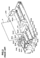
- FIG. 1 is a cross-sectional view showing the configuration of a first printing apparatus to which the present invention can be applied, for example, a laser-beam printer (hereinafter abbreviated as an LBP).
- LBP laser-beam printer
- a main body 1500 of the LBP receives and stores printing information (character codes and the like), form information, macro commands and the like supplied from an external apparatus, such as a host computer or the like connected to the main body 1500, forms corresponding character patterns, form patterns and the like in accordance with the received information, and forms an image on recording paper, serving as a recording medium.
- An operation panel 1501 is provided with switches for operations, an LED (light-emitting diode) display unit and the like.
- a printer control unit 1000 controls the entirety of the main body 1500, and analyzes character information and the like supplied from the external apparatus.
- the printer control unit 1000 mainly converts character information into video signals representing the corresponding character patterns, and outputs the video signals to a laser driver 1502.
- the laser driver 1502 includes circuitry for driving a semiconductor laser 1503, and performs on-off switching of laser light 1504 emitted from the semiconductor laser 1503 in accordance with the input video signals.
- the laser light 1504 is deflected in rightward and leftward directions by a rotating polygon mirror 1505 so as to scan and expose the surface of an electrostatic drum 1506.
- An electrostatic latent image corresponding to the character patterns is thereby formed on the electrostatic drum 1506.
- the electrostatic latent image is developed by a developing unit 1507 disposed around the electrostatic drum 1506, and the developed image is transferred onto recording paper. Cut sheets are used as the recording paper.
- the cut-sheet recording paper is accommodated within a paper cassette 1508 mounted on the main body 1500.
- a sheet of the recording paper is fed within the apparatus by a paper feeding roller 1509, a conveying roller 1510 and conveying rollers 1511, and is supplied to the electrostatic drum 1506.
- FIG. 2 is a diagram illustrating an external appearance of a second printing apparatus to which the present invention can be applied, for example, an ink-jet printing apparatus (an IJRA).
- an IJRA ink-jet printing apparatus
- a carriage HC engaging a screwed groove 5005 of a lead screw 5004 rotating via driving-force transmission gears 5011 and 5009 meshed for movement with the normal/reverse rotation of a driving motor 5013 includes a pin (not shown), and is reciprocated in the directions of arrows "a" and "b".
- An ink-jet cartridge IJC is mounted on the carriage HC.
- a paper-pressing plate 5002 presses paper against a platen 5000 over the moving direction of the carriage HC.
- Photocouplers 5007 and 5008 function as homeposition detection means for, for example, confirming the presence of a lever 5006 of the carriage HC in the region where the photocouplers 5007 and 5008 are present, and performing switching of the direction of the rotation of the motor 5013.
- a member 5016 supports a cap member 5022 for capping the entire surface of a recording head IJH.
- a suction pump 5015 sucks the inside of the cap member 5022, and performs a recovering operation of the recording head by suction via an opening 5023 of the cap member 5022.
- a cleaning blade 5017 is movable in back-and-forth directions by means of a member 5019.
- a supporting plate 5018 supports the cleaning blade 5017 and the member 5019.
- a lever 5021 is used to start suction for recovery, and moves in accordance with the movement of a cam 5020 engaging the carriage HC.
- the driving force of the driving motor 5013 is transmitted by a known transmission means, such as a clutch or the like.
- the apparatus is configured so that desired processing is performed at the corresponding position by the operation of the lead screw 5004 when the carriage HC reaches the home-position-side region. Any configuration may be adopted provided that a desired operation can be performed at a well-known timing.
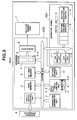
- FIG. 3 is a block diagram showing the configuration of a printing apparatus according to a first embodiment of the present invention. Although an explanation will be provided illustrating the laser-beam printer shown in FIG. 1, the ink-jet printer shown in FIG. 2 or any other type of printing apparatus may also be used.
- an input/output control unit 1 receives document information, image data, commands to call various kinds of settings registered in the apparatus, and the like input from an external apparatus 8, such as a host computer or the like, or outputs setting information of the apparatus, and the like to the external apparatus 8.
- Image data and the like input from the external apparatus 8 via the input/output control unit 1 are stored in a page memory 2 having a capacity for at least one page.
- the data to be stored in the page memory 2 comprise image information, document information, control codes for assigning emphasis of characters, and the like.
- a character-generator unit 3 inputs character-code information when the document information stored in the page memory 2 comprises the character-code information, and outputs the corresponding pattern data to a main control unit 4.
- a bit-map memory 9 develops bit data and the like patterned by the character-generator unit 3.
- the main control unit 4 controls the entirety of the printing apparatus, and includes, for example, a CPU (central processing unit ) 4-3, such as a microprocessor or the like, a ROM (read-only memory) 4-1 for storing various kinds of data, such as control programs (flowcharts shown in FIGS. 4 and 6, and the like), and a RAM (random access memory) 4-2 used as a work area, and the like.
- a CPU central processing unit
- ROM read-only memory
- RAM random access memory
- a scanning buffer 5 includes buffers 5-1 and 5-2 for storing image data used for one-line scanning of a laser beam.
- the reason why the two buffers are provided is that even if one of them outputs data to a printer-engine unit 7 via a serializer 6, the other buffer can store data for the next line.
- the other buffer starts to output data, and data for the next line are transferred to the buffer which has just completed the output of the data. Thereafter, processing is alternately switched to the respective buffers. Thus, high-speed processing is performed.
- An operation panel 1501 includes a reading device comprising an LED (light-emitting diode) display unit 11-1 and an LCD (liquid-crystal display) display unit 11-2, and a switch unit 11-3 for setting various kinds of parameters of the printing apparatus, test printing and the like.
- a reading device comprising an LED (light-emitting diode) display unit 11-1 and an LCD (liquid-crystal display) display unit 11-2, and a switch unit 11-3 for setting various kinds of parameters of the printing apparatus, test printing and the like.
- Various kinds of parameter settings such as a plurality of the kinds of paper cassettes, external interfaces, page description languages, the kinds, pitches, and point sizes of fonts, and the like, or combinations of the settings set by operating the switch unit 11-3 can be registered in a storage device or a setting storage unit 10.
- the registration and calling or retrieving of a combination of various kinds of settings can be performed by a setting registration switch 11-4 and a setting calling switch 11-5, respectively.
- step S2 Various kinds of parameter settings set by operating the operation switch unit 11-3 are displayed on the LED display unit 11-1 or the LCD display unit 11-2. If the setting registration switch 11-4 is depressed when the setting operation has been completed (step S2), the contents of the setting are written and registered in a memory device provided within the setting storage unit 10 (step S3). By repeating the above-described operation, it is possible to register a plurality of set contents in the setting registration unit 10.
- step S4 the CPU 4-3 within the main control unit 4 reads one of the set contents registered in the setting storage unit 10, and switches the setting of the main body of the apparatus (step S5), and displays the read set contents on the LED display unit 11-1 or the LCD display unit 11-2 (step S6).
- a nonvolatile memory such as a flash memory, an EEPROM (electrically erasable/programmable read-only memory), an NVRAM (nonvolatile random access memory) or the like, an SRAM (static random access memory) backed up by a battery, or the like, is used as the memory device within the setting storage unit 10 so that the memory's contents are not lost even if the power supply of the main body of the apparatus is turned off.
- EEPROM electrically erasable/programmable read-only memory
- NVRAM nonvolatile random access memory
- SRAM static random access memory
- the contents set immediately before the turning-off may be written in the memory device within the setting storage unit 10 in accordance with a program stored within the ROM 4-1.
- the CPU 4-3 may read the settings stored in the setting storage unit 10 immediately before the power supply has been turned off stored in the setting storage unit 10, whereby the setting of the main body of the apparatus is performed.
- step S8 When printing data have been actually transmitted while the connection between the printing apparatus and the external apparatus 8 is in an on-line state, a printing operation is performed in accordance with the set contents displayed on the LCD unit 11-2 at that time (step S8).
- the registration or calling of various kinds of setting or combinations of the setting may be executed by a command from the external apparatus 8.
- priority may be given to a command from the external apparatus 8 in accordance with the flowchart shown in FIG. 8.
- step S81 If a command to call other set contents has been received from the external apparatus 8 in step S81, the setting is switched to the other set contents in accordance with the received command in step S83, and the contents are displayed on the display unit in step S84.
- This flowchart is inserted after step S6 of the flowchart shown in FIG. 4, or step S67 of the flowchart shown in FIG. 6 (to be described later), and the process returns to step S1 or step S61 shown in FIG. 6 (to be described later).
- the present invention may, of course, be applied to a case in which the aim of the invention is achieved by supplying a system or an apparatus with a program.
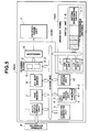
- FIG. 5 is a diagram showing an example of the configuration of a printing apparatus which can arbitrarily set the functions of operation-panel switches. Since components other than a switch unit 11-6 and programmable switches 12 are the same as those shown in FIG. 3, an explanation thereof will be omitted.
- Settings of various kinds of parameters such as the selection of a paper cassette, an external interface, a page description language and the like, or combinations of the settings set by operating the switch unit 11-6 or by the external apparatus 8 are registered in the setting storage unit 10 using a setting registration switch 11-7.
- the user can arbitrarily determine the correspondence between each of the registered contents and each of the programmable switches.
- the set contents registered in the setting storage unit 10 can be called by operating the programmable switch 12 corresponding to each of the contents.
- step S62 the setting registration switch 11-7 is depressed.
- step S63 the set contents registered in step S62 can correspond to the depressed programmable switch 12 (step S63).
- step S64 the set contents are written and registered in the memory device within the setting storage unit 10 together with identifying information of the corresponding programmable switch.
- step S65 it is determined whether or not any of the programmable switches 12 have been depressed. If the result of the determination is affirmative, the CPU 4-3 within the main control unit 4 reads the set contents corresponding to identifying information of the depressed programmable switch (step S66) and switches the setting of the main body of the apparatus, and displays the read set contents on the LED display unit 11-1 or the LCD display unit 11-2 (step S67).
- the setting is switched to another registered setting, whereby the desired set contents can be selected.
- a nonvolatile memory such as a flash memory, an EEPROM (electrically erasable/programmable read-only memory), an NVRAM (nonvolatile random access memory) or the like, an SRAM (static random access memory) backed up by a battery, or the like, is used as the memory device within the setting storage unit 10 so that the memory's contents are not lost even if the power supply of the main body of the apparatus is turned off.
- EEPROM electrically erasable/programmable read-only memory
- NVRAM nonvolatile random access memory
- SRAM static random access memory
- the contents set immediately before the turning-off may be written in the memory device within the setting storage unit 10 in accordance with a program stored within the ROM 4-1.
- the CPU 4-3 may read the settings stored in the setting storage unit 10 immediately before the power supply has been turned off, whereby the setting of the main body of the apparatus is performed.
- step S69 When printing data have been actually transmitted while the connection between the printing apparatus and the external apparatus 8 is in an on-line state, a printing operation is performed in accordance with the set contents displayed on the LCD unit 11-2 at that time (step S69).
- the present invention is not limited to such an operation. It is limited to the appended claims.
- the registration or calling of various kinds of setting or combinations of the setting may be executed by a command from the external apparatus 8.
- priority may be given to a command from the external apparatus 8 in accordance with the flowchart shown in FIG. 8.
- step S81 If a command to call other set contents has been received from the external apparatus 8 in step S81, the setting is switched to the other set contents in accordance with the received command in step S83, and the contents are displayed on the display unit in step S84.
- This flowchart is inserted after step S67 of the flowchart shown in FIG. 6, and the process returns to step S61 shown in FIG. 6.
- the present invention may, of course, be applied to a case in which the object of the invention is achieved by supplying a system or an apparatus with a program.
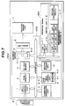
- An LCD display unit 11-2 shown in FIG. 5 may be individually provided for each of the programmable switches 12, as in the block diagram showing the configuration of a printing apparatus according to a third embodiment of the present invention shown in FIG. 7, so that when the user switches the setting of the printing apparatus, the set contents registered in each of the programmable switches 12 can be always confirmed on each of the LCD display units 11-2.
- the operation of the third embodiment is performed in accordance with the flowcharts shown in FIGS. 6 and 8 in a manner similar to that of the second embodiment.
Landscapes
- Engineering & Computer Science (AREA)
- General Engineering & Computer Science (AREA)
- Physics & Mathematics (AREA)
- General Physics & Mathematics (AREA)
- Theoretical Computer Science (AREA)
- Accessory Devices And Overall Control Thereof (AREA)
- Record Information Processing For Printing (AREA)
Claims (8)
- Appareil d'impression comprenant un moyen de définition (11.3, 11.6) pour fixer diverses valeurs concernant des paramètres d'impression, un moyen de réception (1) pour recevoir un groupe de valeurs pour ledit appareil d'impression tel que défini par un appareil externe (8), un moyen de stockage (10) pour stocker au moins un des groupes de valeurs reçus par ledit moyen de réception ainsi que les valeurs fixées par ledit moyen de définition, un moyen de lecture (4.3) pour extraire les valeurs souhaitées dudit moyen de stockage et un moyen de commande (4) pour commander ledit appareil d'impression en fonction des valeurs extraites par ledit moyen de lecture pour permettre de donner la priorité au groupe de valeurs fixé par l'appareil externe, caractérisé en ce que les valeurs fixées par le moyen de définition (11.3, 11.6) comprennent une pluralité de paramètres groupés selon des combinaisons particulières, la combinaison désirée pouvant être sélectionnée globalement, la pluralité de paramètres comprenant la sélection de cassette de papier et celle du pas et du corps de la police d'impression.
- Appareil d'impression selon la revendication 1, dans lequel la pluralité de paramètres comprend, en outre, des interfaces externes.
- Appareil d'impression selon la revendication 1, dans lequel la pluralité de paramètres comprend, en outre, un langage de description de page.
- Appareil d'impression selon la revendication 1, dans lequel la pluralité de paramètres comprend, en outre, le type de police d'impression.
- Procédé d'impression comprenant les étapes consistant à fixer diverses valeurs concernant les paramètres d'impression, à recevoir un groupe de valeurs pour un appareil d'impression tel que défini par un appareil externe, à stocker au moins un des groupes de valeurs reçus ainsi que les valeurs fixées, à extraire les valeurs désirées d'un moyen de stockage, et à commander l'appareil d'impression en fonction des valeurs lues pour permettre de donner la priorité au groupe de valeurs défini par l'appareil externe, caractérisé en ce que les valeurs fixées comprennent une pluralité de paramètres groupés selon des combinaisons particulières, la combinaison désirée étant sélectionnée globalement, la pluralité de paramètres incluant une sélection de cassettes de papier et celle du pas et du corps de la police d'impression.
- Procédé d'impression selon la revendication 5, dans lequel la pluralité de paramètres inclut, en outre, des interfaces externes.
- Procédé d'impression selon la revendication 5, dans lequel la pluralité de paramètres inclut, en outre, un langage de description de page.
- Procédé d'impression selon la revendication 5, dans lequel la pluralité de paramètres inclut, en outre, le type de police d'impression.
Applications Claiming Priority (4)
| Application Number | Priority Date | Filing Date | Title |
|---|---|---|---|
| JP24763391A JPH0585013A (ja) | 1991-09-26 | 1991-09-26 | 印刷装置 |
| JP247633/91 | 1991-09-26 | ||
| JP24800792A JPH0691989A (ja) | 1992-09-17 | 1992-09-17 | 印刷装置及び方法 |
| JP248007/92 | 1992-09-17 |
Publications (3)
| Publication Number | Publication Date |
|---|---|
| EP0534723A2 EP0534723A2 (fr) | 1993-03-31 |
| EP0534723A3 EP0534723A3 (fr) | 1993-06-09 |
| EP0534723B1 true EP0534723B1 (fr) | 1998-07-29 |
Family
ID=26538353
Family Applications (1)
| Application Number | Title | Priority Date | Filing Date |
|---|---|---|---|
| EP92308643A Expired - Lifetime EP0534723B1 (fr) | 1991-09-26 | 1992-09-23 | Appareil d'impression et méthode pour stocker différents paramètres d'impression |
Country Status (3)
| Country | Link |
|---|---|
| US (1) | US5696891A (fr) |
| EP (1) | EP0534723B1 (fr) |
| DE (1) | DE69226410T2 (fr) |
Families Citing this family (6)
| Publication number | Priority date | Publication date | Assignee | Title |
|---|---|---|---|---|
| JPH1063444A (ja) | 1996-08-27 | 1998-03-06 | Riso Kagaku Corp | 画像形成装置用コンピュータインターフェイス装置 |
| DE69716871T2 (de) * | 1997-03-03 | 2003-07-17 | Scitex Digital Printing, Inc. | Selbstkonfigurierender Tintenstrahldrucker |
| US6498611B1 (en) | 2000-01-28 | 2002-12-24 | Lexmark International, Inc. | System and method for providing a virtual operator panel for a peripheral device |
| EP1187058A3 (fr) * | 2000-08-30 | 2003-01-02 | Seiko Epson Corporation | Imprimante, support de stockage de données, interface, méthode de commande d'imprimante, et méthode de contrôle d'interface |
| JP4029391B2 (ja) | 2002-04-12 | 2008-01-09 | リコープリンティングシステムズ株式会社 | プリンタ |
| TWI329262B (en) * | 2003-01-21 | 2010-08-21 | Lenovo Singapore Pte Ltd | Information processing apparatus, communication control method, and communication control program |
Family Cites Families (8)
| Publication number | Priority date | Publication date | Assignee | Title |
|---|---|---|---|---|
| US4891769A (en) * | 1986-04-18 | 1990-01-02 | Canon Kabushiki Kaisha | Printer having prioritized on-line and off-line modes |
| JPH01183729A (ja) * | 1988-01-18 | 1989-07-21 | Citizen Watch Co Ltd | メモリの自動初期化機能を備えたプリンタ |
| US4846597A (en) * | 1988-03-25 | 1989-07-11 | Advanced Matrix Technology, Inc. | Line printer panel and control system |
| US5036476A (en) * | 1988-04-08 | 1991-07-30 | Minolta Camera Kabushiki Kaisha | Printer control system |
| CA1327851C (fr) * | 1988-06-22 | 1994-03-15 | Amy S. Christopher | Imprimante reconfigurable |
| US5075874A (en) * | 1989-04-10 | 1991-12-24 | Eastman Kodak Company | Communications interface for computer output printer |
| US5050098A (en) * | 1989-08-25 | 1991-09-17 | Lexmark International, Inc. | Printer initialization system |
| US5126951A (en) * | 1991-05-28 | 1992-06-30 | Calcomp, Inc. | Simplified menu inputting for a pen plotter |
-
1992
- 1992-09-23 EP EP92308643A patent/EP0534723B1/fr not_active Expired - Lifetime
- 1992-09-23 DE DE69226410T patent/DE69226410T2/de not_active Expired - Fee Related
-
1994
- 1994-06-10 US US08/258,595 patent/US5696891A/en not_active Expired - Lifetime
Also Published As
| Publication number | Publication date |
|---|---|
| DE69226410D1 (de) | 1998-09-03 |
| EP0534723A3 (fr) | 1993-06-09 |
| EP0534723A2 (fr) | 1993-03-31 |
| US5696891A (en) | 1997-12-09 |
| DE69226410T2 (de) | 1998-12-24 |
Similar Documents
| Publication | Publication Date | Title |
|---|---|---|
| EP0571168B1 (fr) | Appareil et méthode pour la traduction d'un langage d'imprimante | |
| EP0619190B1 (fr) | Procédé et appareil pour la sortie d'information | |
| EP0571169B1 (fr) | Appareil et procédé pour générer des motifs de fontes de caractères | |
| US5751922A (en) | Output control apparatus and method with variable output settings | |
| EP0534723B1 (fr) | Appareil d'impression et méthode pour stocker différents paramètres d'impression | |
| EP0571145B1 (fr) | Appareil pour traduire des langages de commande d'imprimante | |
| EP0902357B1 (fr) | Procédé de sortie et dispositif | |
| US6028676A (en) | Output method and apparatus for estimating image quality prior to output | |
| EP0577013A2 (fr) | Méthode et dispositif de contrôle de sortie | |
| US6052204A (en) | Output apparatus and output method | |
| US5899614A (en) | Output method and apparatus | |
| EP0583891B1 (fr) | Dispositif et méthode de sortie | |
| US5617525A (en) | Image outputting adaptable to various fonts | |
| EP0634731B1 (fr) | Méthode et appareil de sortie utilisant plusieurs unités de traitement de données | |
| US5684930A (en) | Output apparatus and method with font control in plural output modes | |
| US20020080383A1 (en) | Output control method and apparatus therefor | |
| US6397265B1 (en) | Print control apparatus for communicating with a selected external apparatus to control a printer | |
| JP3323680B2 (ja) | 出力装置及び出力方法 | |
| JPH0691989A (ja) | 印刷装置及び方法 | |
| JP2871981B2 (ja) | 印刷装置及びその制御方法 | |
| JP3397514B2 (ja) | 出力装置及び出力方法 | |
| JPH0615930A (ja) | 印刷装置 | |
| JPH0740607A (ja) | 画像形成装置及びその制御方法 |
Legal Events
| Date | Code | Title | Description |
|---|---|---|---|
| PUAI | Public reference made under article 153(3) epc to a published international application that has entered the european phase |
Free format text: ORIGINAL CODE: 0009012 |
|
| AK | Designated contracting states |
Kind code of ref document: A2 Designated state(s): DE FR GB IT |
|
| PUAL | Search report despatched |
Free format text: ORIGINAL CODE: 0009013 |
|
| AK | Designated contracting states |
Kind code of ref document: A3 Designated state(s): DE FR GB IT |
|
| 17P | Request for examination filed |
Effective date: 19931022 |
|
| 17Q | First examination report despatched |
Effective date: 19960205 |
|
| GRAG | Despatch of communication of intention to grant |
Free format text: ORIGINAL CODE: EPIDOS AGRA |
|
| GRAG | Despatch of communication of intention to grant |
Free format text: ORIGINAL CODE: EPIDOS AGRA |
|
| GRAH | Despatch of communication of intention to grant a patent |
Free format text: ORIGINAL CODE: EPIDOS IGRA |
|
| GRAH | Despatch of communication of intention to grant a patent |
Free format text: ORIGINAL CODE: EPIDOS IGRA |
|
| GRAA | (expected) grant |
Free format text: ORIGINAL CODE: 0009210 |
|
| AK | Designated contracting states |
Kind code of ref document: B1 Designated state(s): DE FR GB IT |
|
| REF | Corresponds to: |
Ref document number: 69226410 Country of ref document: DE Date of ref document: 19980903 |
|
| ET | Fr: translation filed | ||
| PLBE | No opposition filed within time limit |
Free format text: ORIGINAL CODE: 0009261 |
|
| STAA | Information on the status of an ep patent application or granted ep patent |
Free format text: STATUS: NO OPPOSITION FILED WITHIN TIME LIMIT |
|
| 26N | No opposition filed | ||
| REG | Reference to a national code |
Ref country code: GB Ref legal event code: IF02 |
|
| PGFP | Annual fee paid to national office [announced via postgrant information from national office to epo] |
Ref country code: GB Payment date: 20040909 Year of fee payment: 13 |
|
| PGFP | Annual fee paid to national office [announced via postgrant information from national office to epo] |
Ref country code: FR Payment date: 20040927 Year of fee payment: 13 |
|
| PGFP | Annual fee paid to national office [announced via postgrant information from national office to epo] |
Ref country code: DE Payment date: 20041124 Year of fee payment: 13 |
|
| PG25 | Lapsed in a contracting state [announced via postgrant information from national office to epo] |
Ref country code: IT Free format text: LAPSE BECAUSE OF NON-PAYMENT OF DUE FEES;WARNING: LAPSES OF ITALIAN PATENTS WITH EFFECTIVE DATE BEFORE 2007 MAY HAVE OCCURRED AT ANY TIME BEFORE 2007. THE CORRECT EFFECTIVE DATE MAY BE DIFFERENT FROM THE ONE RECORDED. Effective date: 20050923 Ref country code: GB Free format text: LAPSE BECAUSE OF NON-PAYMENT OF DUE FEES Effective date: 20050923 |
|
| PG25 | Lapsed in a contracting state [announced via postgrant information from national office to epo] |
Ref country code: DE Free format text: LAPSE BECAUSE OF NON-PAYMENT OF DUE FEES Effective date: 20060401 |
|
| GBPC | Gb: european patent ceased through non-payment of renewal fee |
Effective date: 20050923 |
|
| PG25 | Lapsed in a contracting state [announced via postgrant information from national office to epo] |
Ref country code: FR Free format text: LAPSE BECAUSE OF NON-PAYMENT OF DUE FEES Effective date: 20060531 |
|
| REG | Reference to a national code |
Ref country code: FR Ref legal event code: ST Effective date: 20060531 |