EP0529219B1 - Vorrichtung zum Entleeren von Behältern - Google Patents
Vorrichtung zum Entleeren von Behältern Download PDFInfo
- Publication number
- EP0529219B1 EP0529219B1 EP92110097A EP92110097A EP0529219B1 EP 0529219 B1 EP0529219 B1 EP 0529219B1 EP 92110097 A EP92110097 A EP 92110097A EP 92110097 A EP92110097 A EP 92110097A EP 0529219 B1 EP0529219 B1 EP 0529219B1
- Authority
- EP
- European Patent Office
- Prior art keywords
- lifting
- tilting
- control device
- container
- switch
- Prior art date
- Legal status (The legal status is an assumption and is not a legal conclusion. Google has not performed a legal analysis and makes no representation as to the accuracy of the status listed.)
- Expired - Lifetime
Links
Images


Classifications
-
- B—PERFORMING OPERATIONS; TRANSPORTING
- B65—CONVEYING; PACKING; STORING; HANDLING THIN OR FILAMENTARY MATERIAL
- B65F—GATHERING OR REMOVAL OF DOMESTIC OR LIKE REFUSE
- B65F3/00—Vehicles particularly adapted for collecting refuse
-
- B—PERFORMING OPERATIONS; TRANSPORTING
- B65—CONVEYING; PACKING; STORING; HANDLING THIN OR FILAMENTARY MATERIAL
- B65F—GATHERING OR REMOVAL OF DOMESTIC OR LIKE REFUSE
- B65F3/00—Vehicles particularly adapted for collecting refuse
- B65F3/02—Vehicles particularly adapted for collecting refuse with means for discharging refuse receptacles thereinto
- B65F3/04—Linkages, pivoted arms, or pivoted carriers for raising and subsequently tipping receptacles
-
- B—PERFORMING OPERATIONS; TRANSPORTING
- B65—CONVEYING; PACKING; STORING; HANDLING THIN OR FILAMENTARY MATERIAL
- B65F—GATHERING OR REMOVAL OF DOMESTIC OR LIKE REFUSE
- B65F3/00—Vehicles particularly adapted for collecting refuse
- B65F3/001—Vehicles particularly adapted for collecting refuse for segregated refuse collecting, e.g. vehicles with several compartments
Definitions
- the invention relates to a device for emptying containers, in particular garbage containers in collecting containers with at least one tilting or lifting-tilting device, which has a gripping device for gripping the garbage container, and with a pressure medium drive device with an electrical control device, which at least a part of the controls the entire tilting or lifting-tilting process, with at least one acknowledgment signal switch checking the correct seat of the container on the gripping device being connected to the control device.
- Lift-tilt devices are known for emptying garbage containers, which have different control devices.
- automatic controls are known with which the garbage container is emptied and set down again fully automatically after being picked up by the lifting and tilting device.
- Such a fully automatic emptying device is known, for example, from DE-A-3 910 660.
- flap and acknowledgment signal switches are provided on the lifting and tilting device, which are connected to a current flow monitoring device which constantly checks the desired switching state of these switches and only then issues a release signal to the automatic control device, when the switches are switched in the intended manner at the desired time are.
- lifting and tilting devices with a semi-automatic control are also known.
- a lifting and tilting device is described, for example, in WO 89/03794 for emptying small waste containers.
- the waste container to be emptied is brought up to the lifting and tilting device and initially held there by the operator. Then by a second operator At the push of a button, the lifting and tilting device is raised, gripping the edge of the waste container.
- a switch attached to the lifting and tilting device is actuated, which serves to check the correct container seat. If the switch is operated in the prescribed manner, the lifting and tilting process is continued and the container is emptied automatically.
- a disadvantage of this lifting and tilting device is the fact that a person first has to hold the waste container - for example on a downhill road - until a second operator has raised the lifting and tilting device in the receiving position. Since the movement sequence continues without interruption when the container is correctly seated, the operator may also be injured if the container is not released in time.
- a lift-tilt device for emptying garbage containers in which the lift-tilt device is first raised manually and the automatic control of the directional control valve for lifting, holding and lowering only after a specific one Lifting height or lifting time is triggered automatically.
- the automatic emptying process is triggered by a motion detector arranged at a predetermined lifting height.
- a switch which is arranged in the receiving area of the lifting and tilting device and is actuated from the edge of the refuse container, can also be provided, with a time-delayed initiation of the automatic emptying process being ensured.
- An additional operator must also be present when the lifting and tilting device is raised manually. Since the automatic emptying process z. B. triggered by the garbage container, has Operators have no way of first checking that the waste bin is properly seated. The emptying process can only be interrupted by pressing the emergency stop button.
- the object of the invention is therefore a tilting or lifting-tilting device, in which only one operator is required, who himself determine the time of the start of the automatic emptying after the container has been gripped by the gripping device and after an additional visual check of the correct container seat can.
- the lifting phase is understood to mean lifting the lifting and tipping device from its lowest position to a specific, predetermined lifting height, at which the container to be emptied is completely picked up by the gripping device and is lifted off the floor. It is sufficient if the container is only a few centimeters from the ground after the lifting phase has been interrupted.
- the lifting phase of the container is started automatically, but is then interrupted and the subsequent emptying process is started by hand.
- the tilting or lifting-tilting device has at least one of Trash container when actuated to the tilt or tilt device actuated trigger switch.
- This trigger switch can be a flap switch which is actuated by the container wall when the refuse container is brought up to the lifting and tilting device.
- a light barrier for example, which is also triggered by the waste container when it touches the lifting and tilting device.
- Such trigger switches are known per se from automatically operating lift-and-tilt devices, but these trigger switches then trigger the entire lift-and-tilt process.
- This lifting phase is interrupted by the control device after the predetermined lifting height of the tilting or lifting-tilting device has been reached.
- This offers the advantage that the operator, in particular in the case of large containers, has the opportunity once again to check that the refuse container is correctly seated on or on the gripping device.
- At least it is an acknowledgment signal switch is provided, which is arranged, for example, in the area of the receiving comb and is triggered by the edge of the container and thus checks the correct fit of the container, but there may still be cases that the acknowledgment or the acknowledgment signal switch are triggered, but the container may has not yet taken its optimal position on the gripping device. The operator thus once again has the option of making a correction in this regard.
- the operator Since, according to the invention, the subsequent emptying process is not started automatically, the operator must move away from the garbage container and trigger the first manual actuation device, which is preferably attached to the side of the garbage truck or the lifting and tilting device, in order to start the automatic emptying process. There is no danger to the operator because the operator is no longer in the swivel range of the container when the automatic emptying process is triggered.
- the control device can interrupt the lifting phase in different ways.
- the control device preferably comprises a programmable device into which the desired lifting height is entered can. There is also the possibility of designing the control program accordingly, so that the lifting phase is interrupted at the desired time or a desired lifting height.
- At least one stroke limit switch is provided, which is connected to the control device.
- a stroke limit switch can be, for example, a proximity switch, a light barrier, a cam switch or an angle encoder, this stroke limit switch being triggered by the tilting or lifting-tilting device at a predetermined lifting height.
- the stroke limitation switch sends a corresponding signal to the control device, whereupon the control device interrupts the lifting phase.
- This stroke limitation switch is attached to a fixed component of the refuse collection vehicle at a height that corresponds to the specified lifting height.
- control device comprises a timer which emits a signal to interrupt the lifting phase after a predetermined time. This timer is set in motion by the trigger switch, the predetermined time being matched to the lifting speed of the lifting and tilting device.
- the control device is designed to monitor a predetermined first time period between the actuation of the trigger switch and the acknowledgment signal switch. If the lifting phase runs smoothly, there will always be one between the actuation of these two switches certain period of time, which is predetermined by the lifting speed of the lifting and tilting device. If there are problems during the lifting phase, for example if the container edge is not correctly grasped by the pick-up comb and the container may not assume its correct position until a later than the intended time, this irregularity is recognized by the control device due to the time being exceeded.
- the lifting and tilting device is stopped immediately and / or the operator is informed by an acoustic and / or visual display that this lifting phase has not gone smoothly, which in turn is an indication for the operator, once again the correct one Check the fit of the container.
- this first time period can be monitored by the programmable device into which the predetermined time period can be entered.
- a separate monitoring device can also be connected to the control device, which only emits an enable signal to the control device if the predetermined first time period is observed between the actuation of the trigger switch and the acknowledgment signal switch.
- the first period of time is preferably less than 2 seconds.
- the container could already be lifted on one side and still remain on the bottom on the other side, so that the container assumes an inclined position, which results in an incorrect seat on the gripping device when the second single-stroke tilting device is tightened leads and thus does not guarantee a trouble-free sequence of the emptying process.
- the control device is designed to monitor a predetermined second time period between the actuation of at least two trigger switches. Only if the trigger switches are actuated within a predetermined period of time can it be assumed that the container is in its correct starting position on the tilting or lifting-tilting devices. If the predetermined second period of time is observed, the lifting device is started by the control device after actuation of the last trigger switch set. If the specified second period of time has not been observed, the lifting phase of the lifting and tilting device is not triggered, but the trigger switch has already been actuated. Both lifting and tilting devices then remain in their starting position. In addition, an optical feature can tell the operator that problems have arisen with regard to the placement of the garbage container.
- the monitoring of the predefined first and second time period also does not allow any manipulations on the part of the operating personnel. If, for example, one of the trigger switches or acknowledgment signal switches is activated at an earlier point in time or is determined manually, the specified time periods can no longer be observed, which leads to the above-described interruption of the entire lifting process.
- This second time period can also be input into the programmable device or the programmable device is already designed in such a way that it monitors this second time period.
- a second monitoring device can be provided, which is connected to the control device and which only emits an enable signal to the control device if the predetermined second time period has been observed between the actuation of at least two trigger switches.
- This second time period is preferably in the range from 0.4 to 0.8 seconds. In the context of the invention it is also possible to integrate the first and the second monitoring device.
- the control device is designed in such a way that it interrupts the lowering of the refuse container to a predetermined reference height and that a second manual operating device is provided with which the complete lowering of the container can be controlled manually.
- This reference height can correspond to the specified lifting height of the lifting phase.
- the stroke limit switch can be actuated at a predetermined reference height, which is therefore equipped with an additional function. The complete lowering of the container is therefore under the control of the operator.
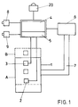
- FIG. 1 A device for emptying containers is shown schematically in FIG. 1, which has a single lifting and tilting device 1.
- this lifting and tilting device 1 has pressure medium motors which are connected to a hydraulic circuit and a pressure medium pump.
- This pressure medium drive device and the connection with the lifting and tilting device 1 are indicated by the reference numerals 6 to 7.
- the lifting and tilting device 1 is equipped with a trigger switch 2 and an acknowledgment signal switch 3.
- the trigger switch 2 is triggered when the refuse container is brought up (not shown), as a result of which a signal is emitted to the control device 4, which has a programmable device 5.
- the control device 4 emits a corresponding signal to one or more elements of the pressure medium drive device 6, so that the lifting and tilting device 1 is moved upward from its starting position A until the predetermined one Stroke height is reached, which is characterized by position B.
- the container to be emptied is gripped by the gripping device, z. B. the edge of the container triggers the receipt signal switch 3.
- the predetermined lifting height is programmed into the programmable device 5, which at a specific point in time emits a corresponding signal to the pressure medium drive device 6, which then the pressure medium motors of the lifting and tilting device 1 stops (not shown).
- the programmable device 5 also takes over the temporal monitoring of the time period between the triggering of the trigger switch 2 and the triggering of the acknowledgment signal switch 3. If the predetermined first time period entered in the programmable device 5 is not adhered to, the control device 4 outputs a corresponding one Signal to the pressure medium drive device 6, which then stops the lift-tilt device 1. In addition, the control device 5 can also activate a warning lamp 20 which indicates to the operating personnel that irregularities have occurred during the lifting phase.
- a first manual control device 8 is connected to the control device 5, with the aid of which the operator can trigger the automatic emptying process after checking that the refuse container is correctly seated on the gripping device of the lifting and tilting device 1.
- the control device 4 then sends a corresponding signal to the pressure medium drive device 6, whereupon the lifting and tilting device leaves position B and, depending on the corresponding design of the mechanics of the tilting or lifting and tilting device 1, further raises the container and then into the pouring opening tilts.
- a shaking process or a lingering of the refuse container can also be provided, the type of movement sequence being controlled by the control device 4 by means of corresponding signals to the pressure medium drive device 6.
- the container is pivoted back and lowered, the lifting and tilting device 1 being stopped at a predetermined reference height, which can correspond to position B.
- a second manual control device 9 which is also connected to the control device 4, the garbage worker can bring about the complete lowering of the lifting and tilting device 1 and thus of the container.
- FIG. 2 schematically shows a device for emptying containers, which has two single-lift-tilt devices 1a and 1b.
- the pressure medium drive device 6 is only shown schematically and the connection between the pressure medium drive device 6 and the lifting and tilting devices is indicated schematically via the connecting line 7a and 7b.
- Each lifting and tilting device 1a and 1b has a trigger switch 2a, 2b and an acknowledgment signal switch 3a and 3b.
- the control device 4 also has a programmable device 5 in this embodiment.
- a first manual control device 8 and a second manual control device 9 are also connected to the control device 4. The mode of operation of the device when emptying a large container is described below, which is emptied jointly by the two individual lifting and tilting devices 1a, 1b.
- the two trigger switches 2a, 2b are actuated more or less simultaneously by the container wall.
- the programmable device 5 takes over the monitoring of the second period between the triggering of the two trigger switches 2a and 2b. If the predetermined second time interval between the triggering of these two trigger switches 2a and 2b is exceeded, none of the single-lift-tilting device 1a or 1b is raised. Both single lift and tilt devices 1 a and 1 b then remain in their starting position A. In this case too, the visual display 20 can be set in motion by the control device 4 in order to inform the operator that this second period of time has not been held irregularities are to be expected.
- the two individual lift and tilt devices 1a and 1b are started up, which can be done independently of one another.
- the acknowledgment signal switches 3a, 3b are actuated from the container edge, one after the other.
- the time period between the triggering of the trigger switch 2a and the acknowledgment signal switch 3a or the trigger switch 2b and the acknowledgment signal switch 3b is additionally monitored. If this first period of time has also been observed for both individual lifting and tipping devices 1a and 1b, the operator can trigger the automatic emptying process via the first manual operating device 8, both individual lifting and tipping devices 1a, 1b emptying the large container together.
- the second manual actuation device 9 also serves to completely lower both single-lift-tilting devices after the container has been emptied.
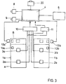
- FIG. 3 A further embodiment is shown in FIG. 3, with a first monitoring device 10 and a second monitoring device 11 now being arranged between the trigger switches 2a, 2b, the acknowledgment signal switches 3a and 3b and the control device 4 instead of the programmable device 5.
- the monitoring of the first time period is carried out by the first monitoring device 10 and the monitoring of the second time period by the second monitoring device 11, which, when the predetermined time periods are observed, emit corresponding release signals to the control device 4, which in turn controls the pressure medium drive device 6 accordingly.
- the connection of the pressure medium drive device 6 with the individual lift-tilt devices 1a and 1b is not shown.
- a stroke limiting switch 12a and 12b which can be designed as a proximity switch, is arranged on each side of the two individual lift-and-tilt devices 1a and 1b. Accordingly, the individual lift-tilt devices 1a and 1b have corresponding contact elements 13a and 13b, which actuate or trigger the switches 12a and 12b when position B is reached.
- These stroke limit switches 12a and 12b are connected to the control device 4 which, in the presence of the corresponding signal, causes the pressure medium drive device 6 to stop the individual stroke and tilt devices 1a and 1b.
- FIG. 4 shows the rear view of a garbage truck 15.
- the Single-stroke-tilting devices 1a and 1b have gripping devices in the form of receiving combs 18a and 18b, which are also designed for gripping large containers.
- a trigger switch 2a and 2b are attached to the front of each of these gripping devices 18a and 18b.
- Acknowledgment signal switches 3a and 3b are arranged behind the gripping devices and are actuated from the container edge when sitting on the gripping devices 18a and 18b.
- These lifting and tilting devices 1a and 1b are actuated by means of swivel arms 19a and 19b which are connected to the pressure medium drive device 6, which cannot be seen in the illustration shown here.
- Stroke limit switches 12a and 12b are fastened to the garbage truck 15 and are actuated when the swivel arms 19a and 19b are pivoted at the predetermined lifting height (position B) and lead to an interruption of the lifting phase.
- the side area of the two lifting and tilting devices is secured by two barriers 14a and 14b.
- First manual control device 8 and second manual control device 9 are shown as buttons on the side of garbage truck 15. By actuating the first manual control device 8, which is only effective when position B is reached and no fault has been reported, the automatic emptying process is triggered, in which the refuse container to be emptied is tipped into the pouring opening 17 of the pouring housing 16. With the help of the second manual control device 9, after the garbage container has been emptied, the garbage container is completely lowered and set down on the street.
Landscapes
- Engineering & Computer Science (AREA)
- Mechanical Engineering (AREA)
- Refuse-Collection Vehicles (AREA)
- Control And Other Processes For Unpacking Of Materials (AREA)
- Refuse Collection And Transfer (AREA)
- Electrical Discharge Machining, Electrochemical Machining, And Combined Machining (AREA)
- Threshing Machine Elements (AREA)
- Processing Of Solid Wastes (AREA)
- Packages (AREA)
- Loading And Unloading Of Fuel Tanks Or Ships (AREA)
- Vending Machines For Individual Products (AREA)
Applications Claiming Priority (2)
| Application Number | Priority Date | Filing Date | Title |
|---|---|---|---|
| DE4128955 | 1991-08-30 | ||
| DE4128955A DE4128955C1 (ko) | 1991-08-30 | 1991-08-30 |
Publications (3)
| Publication Number | Publication Date |
|---|---|
| EP0529219A2 EP0529219A2 (de) | 1993-03-03 |
| EP0529219A3 EP0529219A3 (en) | 1993-05-19 |
| EP0529219B1 true EP0529219B1 (de) | 1995-04-26 |
Family
ID=6439559
Family Applications (1)
| Application Number | Title | Priority Date | Filing Date |
|---|---|---|---|
| EP92110097A Expired - Lifetime EP0529219B1 (de) | 1991-08-30 | 1992-06-16 | Vorrichtung zum Entleeren von Behältern |
Country Status (19)
| Country | Link |
|---|---|
| US (1) | US5322407A (ko) |
| EP (1) | EP0529219B1 (ko) |
| JP (1) | JP3333240B2 (ko) |
| KR (1) | KR100228232B1 (ko) |
| AT (1) | ATE121700T1 (ko) |
| AU (1) | AU656788B2 (ko) |
| CA (1) | CA2077174C (ko) |
| CZ (1) | CZ285163B6 (ko) |
| DE (2) | DE4128955C1 (ko) |
| ES (1) | ES2071381T3 (ko) |
| HU (1) | HU215865B (ko) |
| IE (1) | IE67326B1 (ko) |
| PL (1) | PL169945B1 (ko) |
| RU (1) | RU2087395C1 (ko) |
| SI (1) | SI9200175B (ko) |
| SK (1) | SK279434B6 (ko) |
| TR (1) | TR26165A (ko) |
| YU (1) | YU48493B (ko) |
| ZA (1) | ZA926521B (ko) |
Families Citing this family (9)
| Publication number | Priority date | Publication date | Assignee | Title |
|---|---|---|---|---|
| US5879015A (en) | 1992-02-10 | 1999-03-09 | Ramsey; Michael P. | Method and apparatus for receiving material |
| US5954470A (en) * | 1993-09-09 | 1999-09-21 | Galion Solid Waste Equipment Co, Inc. | Compacting system and refuse vehicle |
| DE4343811C1 (de) * | 1993-12-22 | 1995-03-16 | Sutco Maschinenbau Gmbh | Verfahren zum vollautomatischen Entleeren von Müllgroßbehältern |
| DE4430833C1 (de) * | 1994-08-31 | 1995-11-23 | Zoeller Kipper | Verfahren und Vorrichtung zum Absichern des Arbeitsbereichs von Entleereinrichtungen |
| US6152673A (en) * | 1995-03-07 | 2000-11-28 | Toccoa Metal Technologies, Inc. | Apparatus and method of automated fork repositioning |
| JPH09156707A (ja) * | 1995-12-06 | 1997-06-17 | Fukuoka Subaru Jidosha Kk | ゴミ収集車へのゴミ投入方法及びゴミ収集車用ゴミ投入装置及びゴミ収集車 |
| US5816766A (en) * | 1997-02-11 | 1998-10-06 | Toccoa Metal Technologies, Inc. | Refuse vehicle dumping system |
| GB2404035A (en) | 2003-07-17 | 2005-01-19 | Dow Corning Ltd | Electro-optic gap-cell for waveguide deployment |
| KR102041201B1 (ko) * | 2019-06-21 | 2019-11-27 | 김성기 | 음식물쓰레기 수거장치 |
Family Cites Families (9)
| Publication number | Priority date | Publication date | Assignee | Title |
|---|---|---|---|---|
| DE2721059A1 (de) * | 1977-05-11 | 1978-11-23 | Severin Kuepper | Vorrichtung zum heben, entleeren und senken von muellbehaeltern oder containern |
| DE2847259A1 (de) * | 1978-10-31 | 1980-05-08 | Zoeller Kipper | Hub-kipp- oder kippvorrichtung zum entleeren von behaeltern unterschiedlicher groesse |
| US4479751A (en) * | 1981-12-18 | 1984-10-30 | T C I Products, Inc. | Receptacle dumping apparatus |
| DE3405997A1 (de) * | 1984-02-20 | 1985-08-22 | Zöller-Kipper GmbH, 6500 Mainz | Vorrichtung zum entleeren von behaeltern, insbesondere muellbehaeltern |
| DE3527022A1 (de) * | 1984-08-21 | 1986-03-06 | Zöller-Kipper GmbH, 6500 Mainz | Kipp- oder hubkipp-vorrichtung zum entleeren von behaeltern in sammelbehaelter, vorzugsweise muellbehaelter in den sammelbehaelter eines muellfahrzeugs |
| DE3517491A1 (de) * | 1985-05-15 | 1986-11-20 | G + S Umwelttechnik GmbH, 7107 Nordheim | Hub- oder hub-kipp-vorrichtung zum entleeren von muellbehaeltern in muellfahrzeuge |
| DE3735420A1 (de) * | 1987-10-20 | 1989-05-03 | Wuertz Geb Oswald Renate | Vorrichtung zum entleeren von behaeltern, insbesondere muellbehaeltern |
| US5006030A (en) * | 1989-03-15 | 1991-04-09 | Waste Management Of North America, Inc. | Apparatus for transferring refuse from containers into refuse equipment |
| DE3910660A1 (de) * | 1989-04-03 | 1990-10-04 | Zoeller Kipper | Sicherheitsschaltanordnung fuer hubkipp- oder kippvorrichtungen |
-
1991
- 1991-08-30 DE DE4128955A patent/DE4128955C1/de not_active Expired - Lifetime
-
1992
- 1992-06-16 ES ES92110097T patent/ES2071381T3/es not_active Expired - Lifetime
- 1992-06-16 EP EP92110097A patent/EP0529219B1/de not_active Expired - Lifetime
- 1992-06-16 DE DE59202017T patent/DE59202017D1/de not_active Expired - Fee Related
- 1992-06-16 AT AT92110097T patent/ATE121700T1/de not_active IP Right Cessation
- 1992-07-08 CZ CS922119A patent/CZ285163B6/cs not_active IP Right Cessation
- 1992-07-08 SK SK2119-92A patent/SK279434B6/sk unknown
- 1992-07-30 AU AU20687/92A patent/AU656788B2/en not_active Ceased
- 1992-07-31 IE IE922554A patent/IE67326B1/en not_active IP Right Cessation
- 1992-08-07 YU YU75892A patent/YU48493B/sh unknown
- 1992-08-17 RU SU925052343A patent/RU2087395C1/ru not_active IP Right Cessation
- 1992-08-17 TR TR92/0796A patent/TR26165A/xx unknown
- 1992-08-17 KR KR1019920014784A patent/KR100228232B1/ko not_active IP Right Cessation
- 1992-08-18 SI SI9200175A patent/SI9200175B/sl not_active IP Right Cessation
- 1992-08-27 US US07/936,259 patent/US5322407A/en not_active Expired - Lifetime
- 1992-08-28 ZA ZA926521A patent/ZA926521B/xx unknown
- 1992-08-28 PL PL92295765A patent/PL169945B1/pl not_active IP Right Cessation
- 1992-08-28 HU HU9202783A patent/HU215865B/hu not_active IP Right Cessation
- 1992-08-28 CA CA002077174A patent/CA2077174C/en not_active Expired - Fee Related
- 1992-08-31 JP JP23080992A patent/JP3333240B2/ja not_active Expired - Fee Related
Also Published As
| Publication number | Publication date |
|---|---|
| RU2087395C1 (ru) | 1997-08-20 |
| IE67326B1 (en) | 1996-03-20 |
| DE59202017D1 (de) | 1995-06-01 |
| ES2071381T3 (es) | 1995-06-16 |
| ATE121700T1 (de) | 1995-05-15 |
| JPH05208704A (ja) | 1993-08-20 |
| AU2068792A (en) | 1993-03-04 |
| SI9200175B (en) | 2001-02-28 |
| EP0529219A2 (de) | 1993-03-03 |
| ZA926521B (en) | 1993-04-28 |
| TR26165A (tr) | 1995-02-15 |
| CA2077174A1 (en) | 1993-03-01 |
| PL295765A1 (en) | 1993-05-04 |
| CZ211992A3 (en) | 1993-03-17 |
| YU75892A (sh) | 1995-10-03 |
| CA2077174C (en) | 1997-12-02 |
| HU215865B (hu) | 1999-03-29 |
| PL169945B1 (pl) | 1996-09-30 |
| EP0529219A3 (en) | 1993-05-19 |
| JP3333240B2 (ja) | 2002-10-15 |
| SI9200175A (en) | 1993-03-31 |
| SK211992A3 (en) | 1995-02-08 |
| US5322407A (en) | 1994-06-21 |
| DE4128955C1 (ko) | 1992-11-05 |
| YU48493B (sh) | 1998-09-18 |
| HUT61942A (en) | 1993-03-29 |
| CZ285163B6 (cs) | 1999-05-12 |
| IE922554A1 (en) | 1993-03-10 |
| KR930004166A (ko) | 1993-03-22 |
| AU656788B2 (en) | 1995-02-16 |
| SK279434B6 (sk) | 1998-11-04 |
| HU9202783D0 (en) | 1992-12-28 |
| KR100228232B1 (ko) | 1999-11-01 |
Similar Documents
| Publication | Publication Date | Title |
|---|---|---|
| EP0156445A2 (de) | Vorrichtung zum Entleeren von Behältern, insbesondere Müllbehältern | |
| EP0391225B2 (de) | Sicherheitsschaltanordnung für Hubkipp- oder Kippvorrichtungen | |
| EP0529219B1 (de) | Vorrichtung zum Entleeren von Behältern | |
| EP0278307B1 (de) | Schutzvorrichtung für eine Hubkipp- oder Kippvorrichtung | |
| DE2432712C3 (de) | Reinigungsvorrichtung für die Räder von Landfahrzeugen, insbesondere von Lastkraftwagen | |
| EP0638228A2 (de) | Lösbare Einrichtung zum Anschliessen eines Fangbehälters an eine Mäheinheit | |
| DE2440611A1 (de) | Automatische werkstattanlage | |
| EP0541135B1 (de) | Vorrichtung zum Entleeren von Behältern, insbesondere Müllbehältern | |
| EP0699601B1 (de) | Verfahren und Vorrichtung zum Absichern des Arbeitsbereichs von Entleereinrichtungen | |
| DE102005023154A1 (de) | Müllbehälter-Lifter mit Hinterraum-Überwachung | |
| DE3517491C2 (ko) | ||
| DE4343811C1 (de) | Verfahren zum vollautomatischen Entleeren von Müllgroßbehältern | |
| EP1619143A1 (de) | Verfahren und Vorrichtung zur Absicherung des Arbeitsbereiches von Entleervorrichtungen | |
| EP0593063B1 (de) | Steuereinrichtung für eine handgeführte Arbeitsmaschine mit Fahrantrieb | |
| EP0920793B1 (de) | Steuereinrichtung für Zapfwellen | |
| DE202004007957U1 (de) | Müllbehälter-Lifter mit Hinterraum-Überwachung | |
| DE19644076C2 (de) | Verfahren zur Steuerung einer Hubladebühne und Hubladebühne | |
| EP0734347B1 (de) | Fahrbetriebssicherung für hubkippvorrichtungen | |
| EP1342677A1 (de) | Abfallsammelfahrzeug | |
| DE2742401A1 (de) | Beladevorrichtung fuer schuettgutbehaelter, insbesondere muellwagensammelbehaelter | |
| EP1031520A1 (de) | Vorrichtung zum Entleeren von Behältern, insbesondere Müllbehältern | |
| DE3418108A1 (de) | Werkzeugmaschine mit sicherheitsvorrichtung | |
| DE10161220A1 (de) | Treppensteigvorrichtung | |
| EP2086455A1 (de) | Automatische befüllung eines mundspülbechers |
Legal Events
| Date | Code | Title | Description |
|---|---|---|---|
| PUAI | Public reference made under article 153(3) epc to a published international application that has entered the european phase |
Free format text: ORIGINAL CODE: 0009012 |
|
| AK | Designated contracting states |
Kind code of ref document: A2 Designated state(s): AT BE CH DE ES FR GB GR IT LI LU NL PT SE |
|
| PUAL | Search report despatched |
Free format text: ORIGINAL CODE: 0009013 |
|
| AK | Designated contracting states |
Kind code of ref document: A3 Designated state(s): AT BE CH DE ES FR GB GR IT LI LU NL PT SE |
|
| 17P | Request for examination filed |
Effective date: 19930629 |
|
| 17Q | First examination report despatched |
Effective date: 19940919 |
|
| GRAA | (expected) grant |
Free format text: ORIGINAL CODE: 0009210 |
|
| AK | Designated contracting states |
Kind code of ref document: B1 Designated state(s): AT BE CH DE ES FR GB GR IT LI LU NL PT SE |
|
| REF | Corresponds to: |
Ref document number: 121700 Country of ref document: AT Date of ref document: 19950515 Kind code of ref document: T |
|
| REF | Corresponds to: |
Ref document number: 59202017 Country of ref document: DE Date of ref document: 19950601 |
|
| ITF | It: translation for a ep patent filed |
Owner name: SOCIETA' ITALIANA BREVETTI S.P.A. |
|
| REG | Reference to a national code |
Ref country code: ES Ref legal event code: FG2A Ref document number: 2071381 Country of ref document: ES Kind code of ref document: T3 |
|
| ET | Fr: translation filed | ||
| REG | Reference to a national code |
Ref country code: GR Ref legal event code: FG4A Free format text: 3016022 |
|
| GBT | Gb: translation of ep patent filed (gb section 77(6)(a)/1977) |
Effective date: 19950710 |
|
| SC4A | Pt: translation is available |
Free format text: 950426 AVAILABILITY OF NATIONAL TRANSLATION |
|
| PLBE | No opposition filed within time limit |
Free format text: ORIGINAL CODE: 0009261 |
|
| STAA | Information on the status of an ep patent application or granted ep patent |
Free format text: STATUS: NO OPPOSITION FILED WITHIN TIME LIMIT |
|
| 26N | No opposition filed | ||
| REG | Reference to a national code |
Ref country code: GB Ref legal event code: IF02 |
|
| PGFP | Annual fee paid to national office [announced via postgrant information from national office to epo] |
Ref country code: GB Payment date: 20050603 Year of fee payment: 14 |
|
| PGFP | Annual fee paid to national office [announced via postgrant information from national office to epo] |
Ref country code: PT Payment date: 20050616 Year of fee payment: 14 |
|
| PGFP | Annual fee paid to national office [announced via postgrant information from national office to epo] |
Ref country code: NL Payment date: 20050620 Year of fee payment: 14 |
|
| PGFP | Annual fee paid to national office [announced via postgrant information from national office to epo] |
Ref country code: FR Payment date: 20050621 Year of fee payment: 14 |
|
| PGFP | Annual fee paid to national office [announced via postgrant information from national office to epo] |
Ref country code: BE Payment date: 20050623 Year of fee payment: 14 |
|
| PGFP | Annual fee paid to national office [announced via postgrant information from national office to epo] |
Ref country code: CH Payment date: 20050624 Year of fee payment: 14 |
|
| PGFP | Annual fee paid to national office [announced via postgrant information from national office to epo] |
Ref country code: LU Payment date: 20050627 Year of fee payment: 14 |
|
| PGFP | Annual fee paid to national office [announced via postgrant information from national office to epo] |
Ref country code: AT Payment date: 20050628 Year of fee payment: 14 Ref country code: ES Payment date: 20050628 Year of fee payment: 14 Ref country code: GR Payment date: 20050628 Year of fee payment: 14 |
|
| PGFP | Annual fee paid to national office [announced via postgrant information from national office to epo] |
Ref country code: SE Payment date: 20050629 Year of fee payment: 14 |
|
| PGFP | Annual fee paid to national office [announced via postgrant information from national office to epo] |
Ref country code: DE Payment date: 20050824 Year of fee payment: 14 |
|
| PG25 | Lapsed in a contracting state [announced via postgrant information from national office to epo] |
Ref country code: GB Free format text: LAPSE BECAUSE OF NON-PAYMENT OF DUE FEES Effective date: 20060616 Ref country code: AT Free format text: LAPSE BECAUSE OF NON-PAYMENT OF DUE FEES Effective date: 20060616 |
|
| PG25 | Lapsed in a contracting state [announced via postgrant information from national office to epo] |
Ref country code: ES Free format text: LAPSE BECAUSE OF NON-PAYMENT OF DUE FEES Effective date: 20060617 Ref country code: SE Free format text: LAPSE BECAUSE OF NON-PAYMENT OF DUE FEES Effective date: 20060617 |
|
| PG25 | Lapsed in a contracting state [announced via postgrant information from national office to epo] |
Ref country code: LI Free format text: LAPSE BECAUSE OF NON-PAYMENT OF DUE FEES Effective date: 20060630 Ref country code: CH Free format text: LAPSE BECAUSE OF NON-PAYMENT OF DUE FEES Effective date: 20060630 Ref country code: BE Free format text: LAPSE BECAUSE OF NON-PAYMENT OF DUE FEES Effective date: 20060630 |
|
| PGFP | Annual fee paid to national office [announced via postgrant information from national office to epo] |
Ref country code: IT Payment date: 20060630 Year of fee payment: 15 |
|
| PG25 | Lapsed in a contracting state [announced via postgrant information from national office to epo] |
Ref country code: PT Free format text: LAPSE BECAUSE OF NON-PAYMENT OF DUE FEES Effective date: 20061218 |
|
| PG25 | Lapsed in a contracting state [announced via postgrant information from national office to epo] |
Ref country code: NL Free format text: LAPSE BECAUSE OF NON-PAYMENT OF DUE FEES Effective date: 20070101 |
|
| PG25 | Lapsed in a contracting state [announced via postgrant information from national office to epo] |
Ref country code: DE Free format text: LAPSE BECAUSE OF NON-PAYMENT OF DUE FEES Effective date: 20070103 |
|
| REG | Reference to a national code |
Ref country code: PT Ref legal event code: MM4A Free format text: LAPSE DUE TO NON-PAYMENT OF FEES Effective date: 20061218 |
|
| REG | Reference to a national code |
Ref country code: CH Ref legal event code: PL |
|
| EUG | Se: european patent has lapsed | ||
| GBPC | Gb: european patent ceased through non-payment of renewal fee |
Effective date: 20060616 |
|
| NLV4 | Nl: lapsed or anulled due to non-payment of the annual fee |
Effective date: 20070101 |
|
| REG | Reference to a national code |
Ref country code: FR Ref legal event code: ST Effective date: 20070228 |
|
| REG | Reference to a national code |
Ref country code: ES Ref legal event code: FD2A Effective date: 20060617 |
|
| BERE | Be: lapsed |
Owner name: *ZOLLER-KIPPER G.M.B.H. Effective date: 20060630 |
|
| PG25 | Lapsed in a contracting state [announced via postgrant information from national office to epo] |
Ref country code: FR Free format text: LAPSE BECAUSE OF NON-PAYMENT OF DUE FEES Effective date: 20060630 |
|
| PG25 | Lapsed in a contracting state [announced via postgrant information from national office to epo] |
Ref country code: LU Free format text: LAPSE BECAUSE OF NON-PAYMENT OF DUE FEES Effective date: 20060616 |
|
| PG25 | Lapsed in a contracting state [announced via postgrant information from national office to epo] |
Ref country code: GR Free format text: LAPSE BECAUSE OF NON-PAYMENT OF DUE FEES Effective date: 20070104 |
|
| PG25 | Lapsed in a contracting state [announced via postgrant information from national office to epo] |
Ref country code: IT Free format text: LAPSE BECAUSE OF NON-PAYMENT OF DUE FEES Effective date: 20070616 |