EP0527414B1 - Blindnietgerät - Google Patents
Blindnietgerät Download PDFInfo
- Publication number
- EP0527414B1 EP0527414B1 EP92113186A EP92113186A EP0527414B1 EP 0527414 B1 EP0527414 B1 EP 0527414B1 EP 92113186 A EP92113186 A EP 92113186A EP 92113186 A EP92113186 A EP 92113186A EP 0527414 B1 EP0527414 B1 EP 0527414B1
- Authority
- EP
- European Patent Office
- Prior art keywords
- blind
- tool according
- spindle
- rivet tool
- electric motor
- Prior art date
- Legal status (The legal status is an assumption and is not a legal conclusion. Google has not performed a legal analysis and makes no representation as to the accuracy of the status listed.)
- Expired - Lifetime
Links
- 230000007246 mechanism Effects 0.000 claims abstract description 22
- 230000001934 delay Effects 0.000 claims description 2
- 238000011144 upstream manufacturing Methods 0.000 claims 1
- 230000008878 coupling Effects 0.000 abstract description 2
- 238000010168 coupling process Methods 0.000 abstract description 2
- 238000005859 coupling reaction Methods 0.000 abstract description 2
- 230000005540 biological transmission Effects 0.000 description 9
- 230000002441 reversible effect Effects 0.000 description 5
- 230000008901 benefit Effects 0.000 description 3
- 239000003990 capacitor Substances 0.000 description 3
- 230000006835 compression Effects 0.000 description 3
- 238000007906 compression Methods 0.000 description 3
- 238000000034 method Methods 0.000 description 3
- 230000008569 process Effects 0.000 description 3
- 230000001419 dependent effect Effects 0.000 description 2
- 238000006073 displacement reaction Methods 0.000 description 2
- 239000004065 semiconductor Substances 0.000 description 2
- 230000000903 blocking effect Effects 0.000 description 1
- 230000008859 change Effects 0.000 description 1
- 230000000694 effects Effects 0.000 description 1
- 230000005611 electricity Effects 0.000 description 1
- 239000012530 fluid Substances 0.000 description 1
- 238000004519 manufacturing process Methods 0.000 description 1
- 238000003825 pressing Methods 0.000 description 1
- 230000001681 protective effect Effects 0.000 description 1
Images

Classifications
-
- B—PERFORMING OPERATIONS; TRANSPORTING
- B21—MECHANICAL METAL-WORKING WITHOUT ESSENTIALLY REMOVING MATERIAL; PUNCHING METAL
- B21J—FORGING; HAMMERING; PRESSING METAL; RIVETING; FORGE FURNACES
- B21J15/00—Riveting
- B21J15/10—Riveting machines
- B21J15/30—Particular elements, e.g. supports; Suspension equipment specially adapted for portable riveters
- B21J15/32—Devices for inserting or holding rivets in position with or without feeding arrangements
- B21J15/326—Broken-off mandrel collection
-
- B—PERFORMING OPERATIONS; TRANSPORTING
- B21—MECHANICAL METAL-WORKING WITHOUT ESSENTIALLY REMOVING MATERIAL; PUNCHING METAL
- B21J—FORGING; HAMMERING; PRESSING METAL; RIVETING; FORGE FURNACES
- B21J15/00—Riveting
- B21J15/02—Riveting procedures
- B21J15/04—Riveting hollow rivets mechanically
- B21J15/043—Riveting hollow rivets mechanically by pulling a mandrel
-
- B—PERFORMING OPERATIONS; TRANSPORTING
- B21—MECHANICAL METAL-WORKING WITHOUT ESSENTIALLY REMOVING MATERIAL; PUNCHING METAL
- B21J—FORGING; HAMMERING; PRESSING METAL; RIVETING; FORGE FURNACES
- B21J15/00—Riveting
- B21J15/10—Riveting machines
- B21J15/105—Portable riveters
-
- B—PERFORMING OPERATIONS; TRANSPORTING
- B21—MECHANICAL METAL-WORKING WITHOUT ESSENTIALLY REMOVING MATERIAL; PUNCHING METAL
- B21J—FORGING; HAMMERING; PRESSING METAL; RIVETING; FORGE FURNACES
- B21J15/00—Riveting
- B21J15/10—Riveting machines
- B21J15/16—Drives for riveting machines; Transmission means therefor
- B21J15/26—Drives for riveting machines; Transmission means therefor operated by rotary drive, e.g. by electric motor
-
- Y—GENERAL TAGGING OF NEW TECHNOLOGICAL DEVELOPMENTS; GENERAL TAGGING OF CROSS-SECTIONAL TECHNOLOGIES SPANNING OVER SEVERAL SECTIONS OF THE IPC; TECHNICAL SUBJECTS COVERED BY FORMER USPC CROSS-REFERENCE ART COLLECTIONS [XRACs] AND DIGESTS
- Y10—TECHNICAL SUBJECTS COVERED BY FORMER USPC
- Y10T—TECHNICAL SUBJECTS COVERED BY FORMER US CLASSIFICATION
- Y10T29/00—Metal working
- Y10T29/53—Means to assemble or disassemble
- Y10T29/53709—Overedge assembling means
- Y10T29/53717—Annular work
- Y10T29/53726—Annular work with second workpiece inside annular work one workpiece moved to shape the other
- Y10T29/5373—Annular work with second workpiece inside annular work one workpiece moved to shape the other comprising driver for snap-off-mandrel fastener; e.g., Pop [TM] riveter
- Y10T29/53752—Annular work with second workpiece inside annular work one workpiece moved to shape the other comprising driver for snap-off-mandrel fastener; e.g., Pop [TM] riveter having rotary drive mechanism
-
- Y—GENERAL TAGGING OF NEW TECHNOLOGICAL DEVELOPMENTS; GENERAL TAGGING OF CROSS-SECTIONAL TECHNOLOGIES SPANNING OVER SEVERAL SECTIONS OF THE IPC; TECHNICAL SUBJECTS COVERED BY FORMER USPC CROSS-REFERENCE ART COLLECTIONS [XRACs] AND DIGESTS
- Y10—TECHNICAL SUBJECTS COVERED BY FORMER USPC
- Y10T—TECHNICAL SUBJECTS COVERED BY FORMER US CLASSIFICATION
- Y10T29/00—Metal working
- Y10T29/53—Means to assemble or disassemble
- Y10T29/53709—Overedge assembling means
- Y10T29/5377—Riveter
Definitions
- the invention relates to a blind riveting tool with a housing and a pulling device having a gripping mechanism, which can be moved by an electric motor via a gear device, according to the introductory part of claim 1.
- Such a blind riveting device is known for example from US-A-3095 106.
- US 3 095 106 describes a blind riveting device which generates the longitudinal movement of the pull rod with the aid of a spur gear and a ball screw.
- the spindle is driven.
- the reset takes place after disengaging a clutch via a return spring.
- the transmission ratio of the drive pinion-drawbar gearbox is dependent on the position of the drawbar.
- the translation is the worst at half the movement of the pull rod, in which the mandrel is normally to be torn off, that is to say the highest pulling force is required, since the worst case is the leverage ratio.
- the motor has to apply a relatively large torque, which leads to an increased power requirement. Furthermore, the motor not only has to exert the force to set the blind rivet and tear off the mandrel, it also has to work against the force of the return spring, which increases with increasing displacement of the drawbar.
- the known blind riveting device can be operated with batteries or accumulators. If the voltage of the battery drops so far during the setting process of a blind rivet that the mandrel of the blind rivet can no longer be torn off, it is provided in a special embodiment that the electric motor can be reversed in order to push the pull rod forward and thus the gripping mechanism from the mandrel to loosen the blind rivet.
- US 3,375,883 and US 3,127,045 show further blind riveting devices in which the rotary movement of the electric motor is converted into a linear movement of the pull rod with the aid of a connecting rod drive.
- the connecting rod drive is connected to the permanently running electric motor by means of a coupling.
- a disadvantage of this principle is that half of the possible stroke of the drawbar has the most unfavorable leverage ratios. Since the mandrels are torn off at this position of the pull rod, an engine power is required which, despite the unfavorable transmission ratios, provides sufficient torque to cause the mandrel to tear. This makes the device heavy, which leads to operator fatigue even with short operating times. A large amount of energy is also required.
- the invention has for its object to provide a blind riveting tool that enables more comfortable and energy-saving work.
- the transmission device has a transmission ratio which is independent of the position of the pulling device and forms a permanent operative connection between the electric motor and the pulling device, the movement of the pulling device taking place exclusively under the control of the electric motor.
- the blind riveting device therefore does not require a return spring.
- the power of the electric motor must only be used to pull the mandrel of the blind rivet to be inserted into the blind rivet and later to tear it off.
- the transmission device has a transmission ratio that is independent of the position of the traction device, the electric motor only has to be dimensioned so large that it can apply the necessary breaking torque at the given ratio.
- the motor can therefore be made smaller and therefore lighter than in the known devices. Since no return spring is provided, the pulling device is reset via the electric motor, which is reversible for this purpose. The reversibility of the motor enables the traction device to be moved back to the starting position from practically any position. This avoids unnecessary movements of the pulling device, such as going through the full stroke.
- the tie rod and the electric motor are permanently connected to each other, the electric motor does not move can do without the drawbar is also moved, this means that the electric motor does not have to make any unnecessary movements. Energy is therefore only required for the desired and necessary movements of the pull rod.
- the gear mechanism has a ball screw drive with a nut and a spindle.
- Ball screws convert a rotating movement, ie the rotary movement generated by the electric motor, into a linear movement that is required for the traction device, similar to trapezoidal screws, but they have a much higher efficiency.
- Ball screws are reversible, ie the traction mechanism can move in both directions.
- a ball screw drive is a well-suited example of a gear device for converting a rotary into a translatory movement, in which the transmission ratio is independent of the position of the pulling device.
- the nut is driven and the spindle is connected to the pulling device.
- the overall length can thereby be kept smaller than in the reverse case, which is known from US 3,095,106, since in the reverse case the overall length of the ball screw nut must be increased by at least the maximum possible stroke of the spindle.
- the nut preferably has external teeth.
- Another toothed wheel can mesh with the external toothing, i.e. a toothing on the outer circumference. Since the nut has a larger outer diameter than the spindle, this results in a larger lever, which can be advantageously used.
- the motor can be designed with a weaker torque.
- the spindle is hollow and forms a mandrel disposal path connected to the gripping mechanism.
- the mandrels of the blind rivets to be set therefore no longer have to be disposed of to the front, from where the next blind rivet is to be inserted, they can also be disposed of through the mandrel disposal path to the rear, i.e. through the blind riveting device. This allows for very fluid work since the time otherwise required to dispose of the mandrel released by the gripping mechanism can already be used to insert the mandrel of the next blind rivet.
- a tube is preferably arranged in the housing and extends telescopically into the end of the spindle facing away from the gripping mechanism, the spindle being axially movable relative to the tube.
- the thorn disposal path has a variable length. It extends from the gripping mechanism to the end of the tube. The further the gripping mechanism is moved in the direction of the tear-off position of the mandrel, the shorter the mandrel disposal path becomes. This has the advantage that the overall length of the device does not change during operation. It remains constant with the length that the device has in "idle". This enables work even in confined spaces without having to forego the advantage of thorn disposal to the rear.
- the housing advantageously has a mouthpiece which is supported on the nut via an axial bearing.
- the mouthpiece serves as a contact surface for the blind rivet if the blind rivet is to be placed by pulling on the mandrel. Due to the fact that the mouthpiece is supported directly on the nut, the opposing forces that occur when the mandrel is pulled are derived directly from the parts that generate the force. Only these parts must be dimensioned sufficiently to withstand the tensile forces. The remaining part of the housing can be dimensioned weaker, so it can be made lighter. On the one hand, this results in considerable weight savings. On the other hand, this also reduces the manufacturing effort.
- the mouthpiece is also connected to a cage which at least partially encompasses the mother and which is supported by a second axial bearing on the side of the mother facing away from the mouthpiece. If the electric motor is reversed and the spindle returns to its starting position, forces are exerted on the spindle again at the end of the return stroke, to open the gripping mechanism. These forces are considerably lower than the forces required to tear off the mandrel. However, by using the second axial bearing, these opening forces are also transferred back to the ball screw nut, so that the entire remaining housing remains almost free of forces. The only forces that the housing has to absorb are the bearing forces for the rotational movement of the ball screw nut and a gear wheel driving it. The entire setting mechanism, i.e. the pulling device with gripping mechanism, the mouthpiece and the ball screw drive, can then be manufactured as an interchangeable unit. Measures to transfer larger forces from there to the other parts of the housing do not have to be taken, since this unit absorbs all forces when the rivet is set.
- a stop is preferably arranged on the spindle, at least for one direction of movement, which comes into contact with the nut after a predetermined axial movement of the spindle.
- This stop prevents the spindle from being screwed out of or into the nut so far that it comes into contact with housing parts in such a way that impermissibly high forces are exerted on these housing parts.
- the forces generated by the ball screw are already absorbed by the stop. This also makes the housing relatively easy to carry out, which increases the ease of use. A largely fatigue-free work is possible.
- the electric motor is preceded by an electrical circuit arrangement with an actuation switch, which switches the electric motor in one direction when the actuation switch is actuated and in the other after the actuation has ended Direction drives.
- an actuation switch which switches the electric motor in one direction when the actuation switch is actuated and in the other after the actuation has ended
- Direction drives This embodiment enables particularly simple work.
- the operator wants to place the rivet, he inserts the rivet mandrel into the blind riveting tool and brings the blind rivet to the intended location. Then the operating switch is operated.
- the electric motor now drives the pulling device in one direction until the mandrel of the blind rivet breaks off. Since a further movement of the traction device is no longer necessary, the operator releases the actuation switch. The operation is now finished.
- the circuit arrangement now automatically reverses the motor and thus brings the pulling device back to its starting position, where the old mandrel can be disposed of and a new blind rivet inserted.
- the circuit arrangement briefly short-circuits the electric motor when the actuation switch is actuated. By short-circuiting the electric motor, the motor is braked without a counter voltage acting on it. This keeps the electrical and mechanical load on the motor low.
- the circuit arrangement preferably has at least one controlled switch, the control signal of which can be influenced by the actuation switch.
- the actuation switch does not directly switch the motor currents. It only switches control signals. As a result, the operating switch can be kept small. The operator then only has to exert slight forces to operate it.
- the controlled switch is assigned a delay device which delays the actuation of this switch by a predetermined period of time. This delay can be used, for example, to generate the short circuit which is preferred for braking the motor.
- the advantage here is that the time period is in the same order of magnitude as the stopping time of the unloaded, short-circuited electric motor. It is therefore ensured that the electric motor has come to a standstill before it is reversed. So it can not happen that the motor suddenly receives a counter voltage in full speed. This protects the mechanical parts, e.g. Bearings and gears, which can be dimensioned accordingly small and light.
- two controlled switches designed as changeover switches are provided, which together switch two different short-circuit circuits.
- the electric motor can then be short-circuited from any direction of movement without the need for major circuitry measures.
- At least one limit switch is provided which can be actuated by the spindle and which interrupts the energy supply to the electric motor. Such a limit switch prevents the spindle from being moved beyond a predetermined position and pressing against the housing, which could damage the housing. Such a limit switch can be provided as an alternative or in addition to the stops on the spindle.
- the limit switch deactivates the delay device when actuated.
- the motor In the end position, the motor should not be reversed, which would be caused by the controlled switch. Only the motor should be braked here, for which the direct actuation of the switch is sufficient.
- the limit switch advantageously switches the control signal.
- the limit switch can therefore also be made correspondingly small, since it has practically no power, but only has to switch signals.
- the circuit arrangement advantageously has an overload protection. This switches off the energy supply to the motor if the motor draws too much current, for example due to a torque that is too large. This protects the motor from overloads.
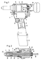
- a blind riveting device 1 has a pulling device 4, which is described in more detail in FIG. 2.
- the traction device 4 is arranged together with a drive motor 5, which is designed as an electric motor, in an outer housing 2.
- the outer housing 2 can, for example, consist of two plastic shell halves constructed essentially symmetrically to one another.
- An accumulator 6 or a battery for supplying power to the motor 5 is arranged in the outer housing 2.
- an actuating switch 7 with an actuating element 37 in the outer housing 2 and, electrically connected between the accumulator 6 and the motor 5, a circuit arrangement 8 described in connection with FIG. 5.
- the motor has an output pinion 9, which meshes with a spur gear 10 of larger diameter.
- This spur gear 10 is rotatably connected to a gear shaft 11, which in turn is rotatably supported in bearings 12 in the outer housing 2.
- a pinion 13 which has a smaller diameter than the spur gear 10.
- the pinion 13 meshes with an external toothing 14 a ball screw nut 15.
- the ball screw nut 15 is in turn rotatably mounted in a bushing which is fixedly arranged in the outer housing 2.
- the ball screw nut 15 rotates on a spindle 16.
- the spindle 16 is secured against rotation by means of torque supports 17, which can be designed as needle bearings and are guided in guideways 18 in the outer housing 2.
- torque supports 17, which can be designed as needle bearings and are guided in guideways 18 in the outer housing 2.
- a gripping mechanism 3 is arranged at one end of the spindle 16, hereinafter referred to as the "front end".
- the gripping mechanism 3 has clamping jaws 19 which are conical on the outside, the thinner diameter of the cone pointing forward.
- the clamping jaws 19 are surrounded by a chuck housing 20 which has a corresponding inner cone.
- a pressure piece 21 is arranged, which is supported on the spindle 16 via a compression spring 22.
- the clamping jaws 19 project forward over the chuck housing 20 here. When the spindle 16 is moved into the front end position, the clamping jaws 19 come to rest against a mouthpiece 23. They then follow up against the force of the compression spring 22 moved behind.
- the mouthpiece 23 is mounted on an inner housing 24 on a thrust bearing 25 which is designed as a thrust bearing and which is supported with its other side on an end face of the ball screw nut 15.
- the force exerted by the spindle 16 on the blind rivet, not shown, is thus absorbed directly by the ball screw nut 15 without the relatively high compressive forces, which correspond to the tensile forces required to tear off the mandrel, to be absorbed by the outer housing 2.
- the outer housing 2 must therefore only be dimensioned to such an extent that it can absorb the torques which are necessary for the rotational movement of the pinion or the ball screw nut 15.
- a stop 26 is supported against which one part of the chuck housing 20 projecting over the diameter of the spindle 16 comes into contact when the spindle 16 has been moved into its extreme rear end position. A further axial displacement of the spindle 16 is blocked by the stop 26 without the outer housing 2 having to absorb the forces necessary for the blocking. These are passed directly to the ball screw nut 15 via the thrust bearing 25.
- a cage 27, which at least partially encompasses the ball screw nut 15, is provided, which is supported at the rear end of the ball nut 15 via a further axial bearing 28 designed as a thrust bearing.
- the mouthpiece 23 is connected on train. If the spindle 16 is now moved into its front end position, the forces exerted by the clamping jaws 19 on the mouthpiece 23 are derived via the cage 27 and the thrust bearing 28 onto the ball screw nut 15. In this case too, the outer housing 2 does not have to absorb any forces. The forces can take on considerable sizes in particular if, due to dirt or jamming, it is difficult to release the clamping jaws 19 from the chuck housing 20.
- the spindle 16 has a through bore 30 in which a mandrel disposal path is arranged.
- the pressure piece 21 has a tubular extension 31.
- the pressure piece 21 is also provided with a through hole extending the bore of the extension, which opens into the free space between the clamping jaws 19.
- the mandrel of the blind rivet which is held between the clamping jaws 19, generally projects at least partially into the pressure piece 21. After demolition, it can be guided through the extension 31 to the rear.
- a tube 32 is telescopically displaceable into the spindle 16 at the rear end. This tube 32 is axially immovably attached to the outer housing.
- the mandrel disposal path is therefore of variable length. Although it ensures the safe and reliable guidance of torn off thorns in every position of the spindle 16, the overall length of the blind riveting device 1 is not increased during operation.
- the pipe 32 opens into a removable collecting container 33 and projects into it by a small length. This prevents torn mandrels that are already in the collecting container 33 from getting back into the tube 32 and thus into the mandrel disposal path. Operation without the collecting container 33 is possible. The mandrels of the blind rivets fall out of the blind riveting device 1.
- two limit switches 34, 35 are arranged at the rear end of the outer housing 2, the limit switch 34 for the front limit position and the limit switch 35 is responsible for the rear end position of the spindle 16.
- the function of the two limit switches 34, 35 is explained in more detail in connection with the circuit arrangement shown in FIG. 5.
- the limit switches are designed so that they switch at or shortly before reaching the respective front or rear end position, thus preventing the spindle 16 from reaching its extreme end position.
- switches are also possible which are not actuated by mechanical forces, for example electronically operating, contactless semiconductor switches or magnetically actuatable switching elements, for example protective gas contact switches.
- the limit switches 34, 35 are preferably arranged so that they are actuated before the stops 26, 29 come into contact with the ball screw nut 15. The stops 26, 29 then form a safety device downstream of the limit switches 34, 35.
- the limit switches 34, 35 and the torque supports 17 are not shown in FIG. 1 for reasons of clarity.
- Fig. 5 shows schematically a circuit arrangement for operating the motor 5, the switch positions for the case of the front end position of the spindle 16 being shown.
- the positive pole of the accumulator 6 is connected on the one hand to a contact 53 of a controlled switch 38, and on the other hand to the movable contact 44 of the actuating switch 7. Furthermore, the positive pole of the accumulator 6 is connected to a contact 56 of a second controlled switch 39.
- the controlled switches each have a relay 40, 41, the one Movable contact 47, 48 switches between two contacts 53, 54 and 55, 56 back and forth.
- the controlled switches 38, 39 can also be designed in the form of semiconductor switches.
- the negative pole of the accumulator 6 is connected to the respective other contacts 54, 55 of the controlled switches 38, 39. It is also connected to a contact 50 of the front limit switch 34 and to a contact 51 of the rear limit switch 35.
- the movable contact 46 of the front limit switch 34 is connected to a control connection of the controlled switch 38.
- the other contact 49 of the front limit switch 34 is connected via a resistor 59 to the other control connection of the controlled switch 38.
- a delay device 42 is arranged in parallel with the controlled switch 38. This is also connected to the two control connections of the controlled switch 38. In the simplest case, the delay device 42 can be formed by a capacitor connected in parallel to the control path of the controlled switch 38.
- the other contact 49 of the front limit switch 34 is connected via a resistor 59 to the control terminal of the controlled switch 38 which is not connected to the movable contact 46 of the front limit switch 34.
- the other controlled switch 39 is connected in a similar manner, ie its two control inputs are connected to a delay device 43.
- One control input is connected to the movable contact 45 of the rear limit switch 35 and the other control input is connected via a resistor 60 to a contact 52 of the rear limit switch 35.
- the two control inputs of the controlled switches 38, 39 which are not connected to the movable contacts 45, 46 of the limit switches 35, 34 are connected to contacts 57, 58 of the actuating switch 7.
- the relay 40 of the one controlled switch 38 switches a movable contact 47, which is connected to the motor 5, between the contact 53 connected to the positive pole of the accumulator 6 and the contact 54 connected to the negative pole of the accumulator 6.
- the relay 41 switches the movable contact 48, which is also connected to the motor 5, between the contact 56 connected to the positive pole of the accumulator 6 and the contact 55 connected to the negative pole of the accumulator 6.
- the entire circuit can also be implemented with other, for example electronic, components with the same function or effect.
- the arrangement works as follows. The state is shown in which the spindle 16 is in the front end position. In this end position, the mandrel of a blind rivet can be inserted into the blind riveting device 1. After the blind rivet has been brought to the desired location, the actuating element 37 of the actuating switch 7 is actuated. Here, the movable contact 44 is released from the contact 58 and connected to the contact 57. There is now a control current path from the positive pole of the accumulator 6 via the movable contact 7, the fixed contact 57, the relay 41 of the controlled switch 39 and the rear limit switch 35 to the negative pole of the accumulator 6. The relay 41 picks up immediately and releases the movable contact 48 from contact 55 and brings it to contact 56 to the system.
- the operator can now let go of the actuating element 37 of the actuating switch 7.
- the movable contact 44 thereby comes into contact with the contact 58.
- the control current path to relay 41 is interrupted.
- the relay 43 prevents the relay from falling off. This results in a short circuit path for the motor 5 via the movable contact 47, the contacts 53 and 56 and the movable contact 48.
- the delay time of the delay device 43 is dimensioned such that it is approximately as long as the braking time of the unloaded, idling motor 5.
- the capacitor 42 is suddenly short-circuited via the resistor 59.
- the relay 40 then drops off immediately and restores the short-circuit circuit shown in FIG. 5 for the motor via the contacts 54 and 55.
- the motor can then brake very quickly, as a result of which the spindle 16 comes to a standstill in its front end position.
- the spindle 16 will actuate the rear limit switch 35, that is to say the movable contact 45 for contacting the contact Bring 52.
- the capacitor 43 is short-circuited.
- the relay 41 of the controlled switch 39 drops out and establishes the short-circuit path shown in FIG. 5 for the motor 5.
- the motor 5 is then braked immediately in the rear end position of the spindle 16.
- the relay 40 is supplied with control current via the front limit switch 34 and the actuation switch 7, whereby the motor 5 is supplied with current via the contact 53 and the contact 55. He then reverses and moves the spindle 16 back towards the front end position.
- the delay device 42 assigned to the controlled switch 38 is provided in the event that the operator presses the actuating element 37 of the actuating switch 7 at a time when the spindle 16 is still being moved into its front end position.
- the delay devices 42, 43 cause the motor 5 to be short-circuited briefly before it receives a current in the opposite direction. This avoids sudden loads on the engine and related parts.
- both the actuation switch 7 and the limit switches 34 and 35 are only acted upon by control currents, which can have a relatively low strength. These switches can therefore be dimensioned relatively weak.
- an overload safety device 61 can also be provided, which interrupts the current flow to the motor, for example, when the current has an amplitude over a predetermined period of time that exceeds a predetermined dimension.
- the operator can avoid all unnecessary movements of the motor 5 without great effort. Since the operator releases the actuating element 37 anyway after the blind rivet mandrel has been torn off, the motor 5 can be reversed immediately and the spindle 16 can be returned to its starting position. Since the motor 5 only has to apply the torque that is necessary to tear off the mandrel of the blind rivet, that is, it does not have to charge any energy store during the movement to tear off the mandrel, it can be smaller and with a lower power consumption be dimensioned. On the one hand, this is advantageous because it allows the weight of the blind riveting device 1 to be kept small, which increases the convenience of work considerably.
- the blind riveting device 1 is particularly suitable for use in connection with a rechargeable battery 6 or a battery, that is to say there are no annoying energy supply lines. This frees up the operator to work.
- a larger amount of blind rivets can be set with a given amount of charge of an accumulator because of the low power consumption.
Landscapes
- Engineering & Computer Science (AREA)
- Mechanical Engineering (AREA)
- Portable Nailing Machines And Staplers (AREA)
- Transmission Devices (AREA)
- Press Drives And Press Lines (AREA)
- Insertion Pins And Rivets (AREA)
- Operating, Guiding And Securing Of Roll- Type Closing Members (AREA)
- Dowels (AREA)
- Orthopedics, Nursing, And Contraception (AREA)
- Details Of Spanners, Wrenches, And Screw Drivers And Accessories (AREA)
- Connection Of Motors, Electrical Generators, Mechanical Devices, And The Like (AREA)
Applications Claiming Priority (2)
| Application Number | Priority Date | Filing Date | Title |
|---|---|---|---|
| DE4126602A DE4126602A1 (de) | 1991-08-12 | 1991-08-12 | Blindnietgeraet |
| DE4126602 | 1991-08-12 |
Publications (2)
| Publication Number | Publication Date |
|---|---|
| EP0527414A1 EP0527414A1 (de) | 1993-02-17 |
| EP0527414B1 true EP0527414B1 (de) | 1995-05-24 |
Family
ID=6438132
Family Applications (1)
| Application Number | Title | Priority Date | Filing Date |
|---|---|---|---|
| EP92113186A Expired - Lifetime EP0527414B1 (de) | 1991-08-12 | 1992-08-03 | Blindnietgerät |
Country Status (11)
| Country | Link |
|---|---|
| US (1) | US5473805A (enExample) |
| EP (1) | EP0527414B1 (enExample) |
| JP (1) | JPH0734966B2 (enExample) |
| AT (1) | ATE122943T1 (enExample) |
| CZ (1) | CZ286429B6 (enExample) |
| DE (1) | DE4126602A1 (enExample) |
| DK (1) | DK0527414T3 (enExample) |
| ES (1) | ES2072669T3 (enExample) |
| HU (1) | HU213721B (enExample) |
| PL (1) | PL170975B1 (enExample) |
| SK (1) | SK247992A3 (enExample) |
Cited By (1)
| Publication number | Priority date | Publication date | Assignee | Title |
|---|---|---|---|---|
| EP2374558A2 (en) | 2010-04-06 | 2011-10-12 | Newfrey LLC | Electric blind rivet setting device |
Families Citing this family (75)
| Publication number | Priority date | Publication date | Assignee | Title |
|---|---|---|---|---|
| US5802691A (en) * | 1994-01-11 | 1998-09-08 | Zoltaszek; Zenon | Rotary driven linear actuator |
| DE4339117C2 (de) * | 1993-11-16 | 1998-07-16 | Gesipa Blindniettechnik | Verfahren zur Überwachung des Setzvorgangs von Blindnieten und Blindnietmuttern und Setzgerät für Blindniete und Blindnietmuttern |
| FR2739794B1 (fr) * | 1995-10-11 | 1997-12-26 | Dassault Aviat | Appareillage de rivetage operant par chocs et procede de mise en oeuvre de cet appareillage |
| US5829115A (en) * | 1996-09-09 | 1998-11-03 | General Electro Mechanical Corp | Apparatus and method for actuating tooling |
| US9015920B2 (en) | 1997-07-21 | 2015-04-28 | Newfrey Llc | Riveting system and process for forming a riveted joint |
| US6276050B1 (en) | 1998-07-20 | 2001-08-21 | Emhart Inc. | Riveting system and process for forming a riveted joint |
| DE19806051A1 (de) * | 1998-02-13 | 1999-08-26 | Honsel M H Beteiligungs Gmbh | Nietsetzgerät |
| DE19818757A1 (de) * | 1998-04-27 | 1999-11-04 | Honsel M H Beteiligungs Gmbh | Nietsetzgerät |
| DE19818756A1 (de) | 1998-04-27 | 1999-11-04 | Honsel M H Beteiligungs Gmbh | Nietsetzgerät |
| DE19818755A1 (de) * | 1998-04-27 | 1999-11-04 | Honsel M H Beteiligungs Gmbh | Nietsetzgerät |
| FR2779670B1 (fr) * | 1998-06-15 | 2000-08-04 | Jean Claude Joux | Appareil electroportatif pour la pose des ecrous a sertir ou le sertissage des rivets aveugles a rupture de tige |
| DE19903020A1 (de) | 1999-01-26 | 2000-08-03 | Honsel M H Beteiligungs Gmbh | Nietsetzgerät |
| GB9923266D0 (en) | 1999-10-02 | 1999-12-08 | Textron Fastening Syst Ltd | Riveting apparatus |
| ITBO20010590A1 (it) * | 2001-09-26 | 2003-03-26 | Far Srl | Pistola rivettatrice elettrica |
| US6910263B2 (en) * | 2001-12-25 | 2005-06-28 | Newfrey Llc | Self-piercing rivet setting apparatus and system |
| EP1477249A1 (en) * | 2001-12-27 | 2004-11-17 | Newfrey LLC | Automatic punching riveting device and die used for the device |
| DE10248298A1 (de) * | 2002-01-21 | 2003-07-31 | Ms Verwaltungs Und Patentgmbh | Setzwerk mit Mitteln zur Kontrolle von Setzvorgängen |
| US6904831B2 (en) * | 2002-11-21 | 2005-06-14 | A. L. Pepper Aasgaard | Rivet setting device for setting self-tapping rivets |
| US7178213B2 (en) * | 2004-06-07 | 2007-02-20 | The Boeing Company | Rivet driving anvil retention system and method |
| DE102005053221A1 (de) * | 2005-11-08 | 2007-05-10 | Bayerische Motoren Werke Ag | Vorrichtung zum Setzen von Blindnietelementen, insbesondere Blindnietschrauben und Blindnietmuttern |
| US20080012453A1 (en) * | 2006-07-17 | 2008-01-17 | Abeo, Llc | Motor having a hollow drive shaft |
| US20090031545A1 (en) * | 2007-08-01 | 2009-02-05 | Abeo, Llc | Rivet gun |
| TW200906566A (en) * | 2007-08-07 | 2009-02-16 | Nat Energy Technology Co Ltd | Electric tool |
| CN101224485B (zh) * | 2008-01-25 | 2010-10-06 | 孙延新 | 拉铆枪 |
| ITBO20080117A1 (it) * | 2008-02-21 | 2009-08-22 | Ober S P A | Dispositivo elettro-idraulico a pistola con controllo elettronico per la deformazione di elementi di fissaggio |
| JP2010260064A (ja) | 2009-04-30 | 2010-11-18 | Nippon Pop Rivets & Fasteners Ltd | ブラインドリベット締結装置 |
| DE102010039661A1 (de) | 2010-08-24 | 2012-04-19 | Adolf Würth GmbH & Co. KG | Nietsetzgerät |
| DE102010039670A1 (de) | 2010-08-24 | 2012-05-16 | Adolf Würth GmbH & Co. KG | Nietsetzgerät |
| JP5674691B2 (ja) | 2012-02-23 | 2015-02-25 | 株式会社ロブテックス | 電動リベッター |
| JP5928803B2 (ja) * | 2012-05-31 | 2016-06-01 | ポップリベット・ファスナー株式会社 | ブラインドリベット締結装置 |
| US9968988B2 (en) | 2012-05-31 | 2018-05-15 | Newfrey Llc | Blind rivet fastening device |
| US20140001224A1 (en) * | 2012-06-28 | 2014-01-02 | Black & Decker Inc. | Cordless fastening tool control system |
| DE102013012223A1 (de) | 2012-08-02 | 2014-02-06 | Richard Bergner Verbindungstechnik Gmbh & Co Kg | Elektroantrieb für ein Bearbeitungswerkzeug wie ein Blindnietsetzgerät, Bearbeitungswerkzeug sowie Verfahren zum geregelten Setzen eines Niets mit einem derartigen Elektoantrieb |
| US9027220B2 (en) | 2012-08-07 | 2015-05-12 | Newfrey Llc | Rivet setting machine |
| DE102012223819A1 (de) | 2012-12-19 | 2014-06-26 | Robert Bosch Gmbh | Nietgerät mit Nietvorrichtung und Antrieb |
| EP2801449A1 (de) * | 2013-05-06 | 2014-11-12 | HILTI Aktiengesellschaft | Eintreibvorrichtung und Verfahren zur Verwendung einer Eintreibvorrichtung |
| DE102013221789B4 (de) * | 2013-10-28 | 2024-06-20 | Robert Bosch Gmbh | Nietsetzgerät mit automatischer Nietdornabführung |
| EP2910321B1 (de) | 2014-02-24 | 2018-10-17 | GESIPA Blindniettechnik GmbH | Blindnietsetzgerät |
| EP2918357B1 (de) | 2014-03-10 | 2016-04-27 | GESIPA Blindniettechnik GmbH | Blindnietsetzgerät |
| US20150305318A1 (en) | 2014-04-23 | 2015-10-29 | William R. Moriarty | Furniture Protector against Crawling Arthropods |
| EP2985093B1 (de) | 2014-08-15 | 2019-05-29 | GESIPA Blindniettechnik GmbH | Blindnietsetzgerät und Verfahren zum Setzen eines Blindniets |
| DE102014226162A1 (de) * | 2014-12-17 | 2016-06-23 | Robert Bosch Gmbh | Werkzeug und verfahren zur behandlung eines werkstücks mit einemwerkzeugelement eines werkzeugs |
| DE102015205995A1 (de) * | 2015-04-02 | 2016-10-06 | Ribe Anlagentechnik Gmbh | Antriebseinheit für eine Setzvorrichtung, insbesondere ein Nietsetzgerät |
| CN104999410B (zh) * | 2015-07-17 | 2017-03-22 | 上海特倍孚铆接工具制造有限公司 | 电动铆螺母工具 |
| WO2018082036A1 (zh) * | 2016-11-04 | 2018-05-11 | 洪劲松 | 铆接传动装置及电动铆钉枪 |
| JP6863723B2 (ja) * | 2016-11-30 | 2021-04-21 | 株式会社マキタ | 締結工具 |
| DE102016124746A1 (de) * | 2016-12-19 | 2018-06-21 | Mtg Hartmut Thiele Gmbh | Nietwerkzeug |
| US11161168B2 (en) | 2017-06-19 | 2021-11-02 | Makita Corporation | Fastening tool |
| JP6768999B2 (ja) * | 2017-06-19 | 2020-10-14 | 株式会社マキタ | 締結工具 |
| JP6822904B2 (ja) * | 2017-06-19 | 2021-01-27 | 株式会社マキタ | 締結工具 |
| JP6768998B2 (ja) * | 2017-06-19 | 2020-10-14 | 株式会社マキタ | 締結工具 |
| DE102017119749B4 (de) * | 2017-08-29 | 2021-02-11 | Vvg-Befestigungstechnik Gmbh & Co. | Handhabbares Blindnietgerät mit umgekehrtem Nietzyklus zum Festhalten eines Blindniets |
| CN207915402U (zh) | 2018-02-13 | 2018-09-28 | 米沃奇电动工具公司 | 用于铆钉设置工具的鼻夹组 |
| CN108994244B (zh) * | 2018-08-30 | 2020-03-06 | 王恩能 | 一种便携式电动铆钉装配辅助机械 |
| US11673243B2 (en) | 2018-09-05 | 2023-06-13 | Milwaukee Electric Tool Corporation | Blind rivet nut-setting tool |
| JP7422508B2 (ja) * | 2019-09-06 | 2024-01-26 | 株式会社マキタ | 締結工具 |
| JP7373946B2 (ja) * | 2019-09-06 | 2023-11-06 | 株式会社マキタ | 締結工具 |
| US11396038B2 (en) * | 2019-09-06 | 2022-07-26 | Makita Corporation | Fastening tool |
| CN110947894B (zh) * | 2019-12-04 | 2021-08-03 | 航天精工股份有限公司 | 一种可调预紧力机械锁紧型抽芯铆钉安装工具 |
| CN219632508U (zh) | 2020-06-03 | 2023-09-05 | 米沃奇电动工具公司 | 用于安置铆钉的铆钉工具及动力工具 |
| TWI745048B (zh) * | 2020-08-25 | 2021-11-01 | 朝程工業股份有限公司 | 電動拉帽機 |
| JP7575995B2 (ja) * | 2021-05-10 | 2024-10-30 | 株式会社マキタ | 締結工具 |
| US12453999B2 (en) | 2021-07-28 | 2025-10-28 | Milwaukee Electric Tool Corporation | Blind rivet nut-setting tool |
| DE102022116413A1 (de) | 2022-06-30 | 2024-01-04 | SFS Group Germany GmbH | Nietgerät mit Federelement integrierter Gewindespindel |
| DE102022116419A1 (de) | 2022-06-30 | 2024-01-04 | SFS Group Germany GmbH | Nietgerät in kompakter Bauweise |
| DE102022116406A1 (de) * | 2022-06-30 | 2024-01-04 | SFS Group Germany GmbH | Nietgerät in kompakter Bauweise |
| DE102022116432A1 (de) | 2022-06-30 | 2024-01-04 | SFS Group Germany GmbH | Nietgerät, Auffangbehälter für Restnietdorne sowie Verfahren zum Montieren und Demontieren eines solchen Auffangbehälters |
| DE102022116417A1 (de) | 2022-06-30 | 2024-01-04 | SFS Group Germany GmbH | Nietgerät, Dornaufnahme und Verfahren zum Zusammenbau eines Nietgerätes |
| CN119585061A (zh) | 2022-06-30 | 2025-03-07 | Sfs集团德国有限公司 | 铆接装置、用于残留铆钉芯轴的收集容器及用于安装和拆卸该收集容器的方法 |
| DE202022103657U1 (de) | 2022-06-30 | 2023-07-05 | SFS Group Germany GmbH | Nietgerät mit verbesserter Handhabbarkeit |
| DE102022116433A1 (de) | 2022-06-30 | 2024-01-04 | SFS Group Germany GmbH | Nietgerät mit verbesserter Handhabbarkeit |
| DE102022116431A1 (de) | 2022-06-30 | 2024-01-04 | SFS Group Germany GmbH | Nietgerät in kompakter Bauweise |
| DE102022116422A1 (de) | 2022-06-30 | 2024-01-04 | SFS Group Germany GmbH | Nietgerät mit wirkungsgradoptimierter Antriebseinrichtung |
| WO2024010932A1 (en) | 2022-07-08 | 2024-01-11 | Milwaukee Electric Tool Corporation | Power tool sensing a multi-pole magnet junction |
| DE102023110985A1 (de) | 2023-04-28 | 2024-10-31 | Bayerische Motoren Werke Aktiengesellschaft | Verfahren zur Herstellung einer elektrisch leitenden Nietverbindung mittels Dornbruchblindniet und dafür geeigneter Dornbruchblindniet |
Family Cites Families (12)
| Publication number | Priority date | Publication date | Assignee | Title |
|---|---|---|---|---|
| US3127045A (en) * | 1964-03-31 | Blind rivet setting tools | ||
| US2400354A (en) * | 1942-09-28 | 1946-05-14 | Whitney Metal Tool Company | Rivet setting tool |
| US3095106A (en) * | 1961-12-28 | 1963-06-25 | United Shoe Machinery Corp | Automatic rivet setting tools |
| US3375883A (en) * | 1965-10-22 | 1968-04-02 | Gesipa Ges Fur Internationale | Electric hand riveting device |
| JPS532229B2 (enExample) * | 1973-04-10 | 1978-01-26 | ||
| IL42637A0 (en) * | 1973-07-01 | 1973-10-25 | Benimatzky E | Device for riveting blind rivets |
| US4085337A (en) * | 1975-10-07 | 1978-04-18 | Moeller Wolfgang W | Electric drill multi-functional apparatus |
| US4063443A (en) * | 1976-11-05 | 1977-12-20 | H. K. Porter Company, Inc. | Rod gripping tool for applying fasteners |
| IT1137442B (it) * | 1981-04-09 | 1986-09-10 | Ocap Di Alda Galeazzi | Rivettatrice sfruttante piani inclinati per l'applicazione di trazione a una spina di ribattino |
| JPS59153538A (ja) * | 1983-02-21 | 1984-09-01 | Katsuyuki Totsu | 電動リベツト工具 |
| JPH02137638A (ja) * | 1988-11-18 | 1990-05-25 | Japan Storage Battery Co Ltd | コードレス・リベットかしめ装置 |
| FI84887C (fi) * | 1990-02-01 | 1992-02-10 | Krister Juntunen | Nitanordning. |
-
1991
- 1991-08-12 DE DE4126602A patent/DE4126602A1/de active Granted
-
1992
- 1992-07-31 PL PL92295480A patent/PL170975B1/pl unknown
- 1992-08-03 EP EP92113186A patent/EP0527414B1/de not_active Expired - Lifetime
- 1992-08-03 DK DK92113186.8T patent/DK0527414T3/da active
- 1992-08-03 AT AT92113186T patent/ATE122943T1/de not_active IP Right Cessation
- 1992-08-03 ES ES92113186T patent/ES2072669T3/es not_active Expired - Lifetime
- 1992-08-05 HU HU9202543A patent/HU213721B/hu not_active IP Right Cessation
- 1992-08-07 JP JP4211381A patent/JPH0734966B2/ja not_active Expired - Fee Related
- 1992-08-11 SK SK2479-92A patent/SK247992A3/sk unknown
- 1992-08-11 CZ CS19922479A patent/CZ286429B6/cs not_active IP Right Cessation
-
1994
- 1994-01-06 US US08/177,808 patent/US5473805A/en not_active Expired - Fee Related
Cited By (1)
| Publication number | Priority date | Publication date | Assignee | Title |
|---|---|---|---|---|
| EP2374558A2 (en) | 2010-04-06 | 2011-10-12 | Newfrey LLC | Electric blind rivet setting device |
Also Published As
| Publication number | Publication date |
|---|---|
| PL295480A1 (en) | 1993-07-26 |
| HUT62218A (en) | 1993-04-28 |
| DE4126602A1 (de) | 1993-02-18 |
| JPH05200476A (ja) | 1993-08-10 |
| DK0527414T3 (da) | 1995-08-14 |
| ES2072669T3 (es) | 1995-07-16 |
| CZ247992A3 (en) | 1993-02-17 |
| SK279693B6 (sk) | 1999-02-11 |
| SK247992A3 (en) | 1999-02-11 |
| HU213721B (en) | 1997-09-29 |
| JPH0734966B2 (ja) | 1995-04-19 |
| US5473805A (en) | 1995-12-12 |
| PL170975B1 (pl) | 1997-02-28 |
| EP0527414A1 (de) | 1993-02-17 |
| ATE122943T1 (de) | 1995-06-15 |
| CZ286429B6 (en) | 2000-04-12 |
| DE4126602C2 (enExample) | 1993-06-09 |
Similar Documents
| Publication | Publication Date | Title |
|---|---|---|
| EP0527414B1 (de) | Blindnietgerät | |
| EP0670199B1 (de) | Blindnietmutter-Setzgerät | |
| EP2599568B1 (de) | Bohrvorrichtung | |
| EP0804315B1 (de) | Werkzeugmaschine | |
| DE2726818C3 (de) | Überlast-Einrichtung für ein elektrisch angetriebenes Werkzeug | |
| DE112011103764B4 (de) | Elektrisch angetriebenes Ausgabewerkzeug | |
| EP0463990B1 (de) | Elektrisch betriebenes Austraggerät | |
| DE2709946C2 (de) | Tragbares Handwerkzeug | |
| EP0953390A2 (de) | Nietsetzgerät | |
| DE3809000C2 (enExample) | ||
| EP0591098A1 (de) | Elektrisch betriebenes Austraggerät | |
| EP0953388A2 (de) | Nietsetzgerät | |
| DE102016203265A1 (de) | Stellanordnung und Klappensteuervorrichtung mit einer Stellanordnung | |
| DE102012011675B4 (de) | Axialzugvorrichtung sowie Werkzeugmaschine mit einer Axialzugvorrichtung | |
| EP0510337B1 (de) | Einstellvorrichtung für rotierende Elemente von Rotationsdruckmaschinen | |
| DE4328599A1 (de) | Rotations-Schlagwerkzeug | |
| DE1103723B (de) | Einrichtung zum Spannen und Loesen von Werkzeugen | |
| DE19605827C2 (de) | Kabelloses Befestigungswerkzeug | |
| EP0953389A2 (de) | Nietsetzgerät | |
| CH671802A5 (enExample) | ||
| DE3510642A1 (de) | Stelleinrichtung, insbesondere zur tuerverriegelung bei kraftfahrzeugen | |
| DE1530260B1 (de) | Slack adjuster | |
| DE4215964C2 (de) | Elektrisch arbeitender Schubantrieb | |
| DE2230082B2 (de) | Blindnietgerät | |
| DE19819251B4 (de) | Handnietgerät zum Setzen von Blindnietmuttern |
Legal Events
| Date | Code | Title | Description |
|---|---|---|---|
| PUAI | Public reference made under article 153(3) epc to a published international application that has entered the european phase |
Free format text: ORIGINAL CODE: 0009012 |
|
| 17P | Request for examination filed |
Effective date: 19921214 |
|
| AK | Designated contracting states |
Kind code of ref document: A1 Designated state(s): AT BE CH DK ES FR GB IT LI NL SE |
|
| 17Q | First examination report despatched |
Effective date: 19940314 |
|
| GRAA | (expected) grant |
Free format text: ORIGINAL CODE: 0009210 |
|
| AK | Designated contracting states |
Kind code of ref document: B1 Designated state(s): AT BE CH DK ES FR GB IT LI NL SE |
|
| REF | Corresponds to: |
Ref document number: 122943 Country of ref document: AT Date of ref document: 19950615 Kind code of ref document: T |
|
| ITF | It: translation for a ep patent filed | ||
| GBT | Gb: translation of ep patent filed (gb section 77(6)(a)/1977) |
Effective date: 19950612 |
|
| REG | Reference to a national code |
Ref country code: ES Ref legal event code: FG2A Ref document number: 2072669 Country of ref document: ES Kind code of ref document: T3 |
|
| REG | Reference to a national code |
Ref country code: DK Ref legal event code: T3 |
|
| ET | Fr: translation filed | ||
| PLAV | Examination of admissibility of opposition |
Free format text: ORIGINAL CODE: EPIDOS OPEX |
|
| PLBI | Opposition filed |
Free format text: ORIGINAL CODE: 0009260 |
|
| PLBQ | Unpublished change to opponent data |
Free format text: ORIGINAL CODE: EPIDOS OPPO |
|
| PLAV | Examination of admissibility of opposition |
Free format text: ORIGINAL CODE: EPIDOS OPEX |
|
| PLBF | Reply of patent proprietor to notice(s) of opposition |
Free format text: ORIGINAL CODE: EPIDOS OBSO |
|
| 26 | Opposition filed |
Opponent name: AVDEL TEXTRON LIMITED Effective date: 19960226 |
|
| NLR1 | Nl: opposition has been filed with the epo |
Opponent name: AVDEL TEXTRON LIMITED |
|
| PLBF | Reply of patent proprietor to notice(s) of opposition |
Free format text: ORIGINAL CODE: EPIDOS OBSO |
|
| PLBO | Opposition rejected |
Free format text: ORIGINAL CODE: EPIDOS REJO |
|
| PLBN | Opposition rejected |
Free format text: ORIGINAL CODE: 0009273 |
|
| STAA | Information on the status of an ep patent application or granted ep patent |
Free format text: STATUS: OPPOSITION REJECTED |
|
| 27O | Opposition rejected |
Effective date: 19970201 |
|
| NLR2 | Nl: decision of opposition | ||
| REG | Reference to a national code |
Ref country code: GB Ref legal event code: IF02 |
|
| PGFP | Annual fee paid to national office [announced via postgrant information from national office to epo] |
Ref country code: DK Payment date: 20030722 Year of fee payment: 12 |
|
| PGFP | Annual fee paid to national office [announced via postgrant information from national office to epo] |
Ref country code: SE Payment date: 20030728 Year of fee payment: 12 |
|
| PGFP | Annual fee paid to national office [announced via postgrant information from national office to epo] |
Ref country code: ES Payment date: 20040721 Year of fee payment: 13 |
|
| PGFP | Annual fee paid to national office [announced via postgrant information from national office to epo] |
Ref country code: BE Payment date: 20040722 Year of fee payment: 13 |
|
| PGFP | Annual fee paid to national office [announced via postgrant information from national office to epo] |
Ref country code: FR Payment date: 20040728 Year of fee payment: 13 Ref country code: GB Payment date: 20040728 Year of fee payment: 13 |
|
| PG25 | Lapsed in a contracting state [announced via postgrant information from national office to epo] |
Ref country code: SE Free format text: LAPSE BECAUSE OF NON-PAYMENT OF DUE FEES Effective date: 20040804 |
|
| PG25 | Lapsed in a contracting state [announced via postgrant information from national office to epo] |
Ref country code: DK Free format text: LAPSE BECAUSE OF NON-PAYMENT OF DUE FEES Effective date: 20040831 |
|
| PGFP | Annual fee paid to national office [announced via postgrant information from national office to epo] |
Ref country code: AT Payment date: 20040831 Year of fee payment: 13 Ref country code: NL Payment date: 20040831 Year of fee payment: 13 |
|
| PGFP | Annual fee paid to national office [announced via postgrant information from national office to epo] |
Ref country code: CH Payment date: 20041021 Year of fee payment: 13 |
|
| EUG | Se: european patent has lapsed | ||
| REG | Reference to a national code |
Ref country code: DK Ref legal event code: EBP |
|
| PG25 | Lapsed in a contracting state [announced via postgrant information from national office to epo] |
Ref country code: IT Free format text: LAPSE BECAUSE OF NON-PAYMENT OF DUE FEES;WARNING: LAPSES OF ITALIAN PATENTS WITH EFFECTIVE DATE BEFORE 2007 MAY HAVE OCCURRED AT ANY TIME BEFORE 2007. THE CORRECT EFFECTIVE DATE MAY BE DIFFERENT FROM THE ONE RECORDED. Effective date: 20050803 Ref country code: AT Free format text: LAPSE BECAUSE OF NON-PAYMENT OF DUE FEES Effective date: 20050803 Ref country code: GB Free format text: LAPSE BECAUSE OF NON-PAYMENT OF DUE FEES Effective date: 20050803 |
|
| PG25 | Lapsed in a contracting state [announced via postgrant information from national office to epo] |
Ref country code: ES Free format text: LAPSE BECAUSE OF NON-PAYMENT OF DUE FEES Effective date: 20050804 |
|
| PG25 | Lapsed in a contracting state [announced via postgrant information from national office to epo] |
Ref country code: LI Free format text: LAPSE BECAUSE OF NON-PAYMENT OF DUE FEES Effective date: 20050831 Ref country code: BE Free format text: LAPSE BECAUSE OF NON-PAYMENT OF DUE FEES Effective date: 20050831 Ref country code: CH Free format text: LAPSE BECAUSE OF NON-PAYMENT OF DUE FEES Effective date: 20050831 |
|
| PG25 | Lapsed in a contracting state [announced via postgrant information from national office to epo] |
Ref country code: NL Free format text: LAPSE BECAUSE OF NON-PAYMENT OF DUE FEES Effective date: 20060301 |
|
| REG | Reference to a national code |
Ref country code: CH Ref legal event code: PL |
|
| GBPC | Gb: european patent ceased through non-payment of renewal fee |
Effective date: 20050803 |
|
| PG25 | Lapsed in a contracting state [announced via postgrant information from national office to epo] |
Ref country code: FR Free format text: LAPSE BECAUSE OF NON-PAYMENT OF DUE FEES Effective date: 20060428 |
|
| NLV4 | Nl: lapsed or anulled due to non-payment of the annual fee |
Effective date: 20060301 |
|
| REG | Reference to a national code |
Ref country code: FR Ref legal event code: ST Effective date: 20060428 |
|
| REG | Reference to a national code |
Ref country code: ES Ref legal event code: FD2A Effective date: 20050804 |
|
| BERE | Be: lapsed |
Owner name: *GESIPA BLINDNIETTECHNIK G.M.B.H. Effective date: 20050831 |