EP0524514A1 - Récipient d'emballage tubulaire multicouche et procédé et dispositif pour la fabrication d'un tel récipient - Google Patents
Récipient d'emballage tubulaire multicouche et procédé et dispositif pour la fabrication d'un tel récipient Download PDFInfo
- Publication number
- EP0524514A1 EP0524514A1 EP19920111864 EP92111864A EP0524514A1 EP 0524514 A1 EP0524514 A1 EP 0524514A1 EP 19920111864 EP19920111864 EP 19920111864 EP 92111864 A EP92111864 A EP 92111864A EP 0524514 A1 EP0524514 A1 EP 0524514A1
- Authority
- EP
- European Patent Office
- Prior art keywords
- sleeve
- inner sleeve
- packaging container
- container according
- outer sleeve
- Prior art date
- Legal status (The legal status is an assumption and is not a legal conclusion. Google has not performed a legal analysis and makes no representation as to the accuracy of the status listed.)
- Withdrawn
Links
Images


Classifications
-
- B—PERFORMING OPERATIONS; TRANSPORTING
- B31—MAKING ARTICLES OF PAPER, CARDBOARD OR MATERIAL WORKED IN A MANNER ANALOGOUS TO PAPER; WORKING PAPER, CARDBOARD OR MATERIAL WORKED IN A MANNER ANALOGOUS TO PAPER
- B31C—MAKING WOUND ARTICLES, e.g. WOUND TUBES, OF PAPER, CARDBOARD OR MATERIAL WORKED IN A MANNER ANALOGOUS TO PAPER
- B31C3/00—Making tubes or pipes by feeding obliquely to the winding mandrel centre line
- B31C3/02—Making tubes or pipes by feeding obliquely to the winding mandrel centre line and inserting into a tube end a bottom to form a container
-
- B—PERFORMING OPERATIONS; TRANSPORTING
- B29—WORKING OF PLASTICS; WORKING OF SUBSTANCES IN A PLASTIC STATE IN GENERAL
- B29C—SHAPING OR JOINING OF PLASTICS; SHAPING OF MATERIAL IN A PLASTIC STATE, NOT OTHERWISE PROVIDED FOR; AFTER-TREATMENT OF THE SHAPED PRODUCTS, e.g. REPAIRING
- B29C65/00—Joining or sealing of preformed parts, e.g. welding of plastics materials; Apparatus therefor
- B29C65/02—Joining or sealing of preformed parts, e.g. welding of plastics materials; Apparatus therefor by heating, with or without pressure
- B29C65/18—Joining or sealing of preformed parts, e.g. welding of plastics materials; Apparatus therefor by heating, with or without pressure using heated tools
-
- B—PERFORMING OPERATIONS; TRANSPORTING
- B29—WORKING OF PLASTICS; WORKING OF SUBSTANCES IN A PLASTIC STATE IN GENERAL
- B29C—SHAPING OR JOINING OF PLASTICS; SHAPING OF MATERIAL IN A PLASTIC STATE, NOT OTHERWISE PROVIDED FOR; AFTER-TREATMENT OF THE SHAPED PRODUCTS, e.g. REPAIRING
- B29C66/00—General aspects of processes or apparatus for joining preformed parts
- B29C66/50—General aspects of joining tubular articles; General aspects of joining long products, i.e. bars or profiled elements; General aspects of joining single elements to tubular articles, hollow articles or bars; General aspects of joining several hollow-preforms to form hollow or tubular articles
- B29C66/51—Joining tubular articles, profiled elements or bars; Joining single elements to tubular articles, hollow articles or bars; Joining several hollow-preforms to form hollow or tubular articles
- B29C66/54—Joining several hollow-preforms, e.g. half-shells, to form hollow articles, e.g. for making balls, containers; Joining several hollow-preforms, e.g. half-cylinders, to form tubular articles
- B29C66/542—Joining several hollow-preforms, e.g. half-shells, to form hollow articles, e.g. for making balls, containers; Joining several hollow-preforms, e.g. half-cylinders, to form tubular articles joining hollow covers or hollow bottoms to open ends of container bodies
-
- B—PERFORMING OPERATIONS; TRANSPORTING
- B29—WORKING OF PLASTICS; WORKING OF SUBSTANCES IN A PLASTIC STATE IN GENERAL
- B29C—SHAPING OR JOINING OF PLASTICS; SHAPING OF MATERIAL IN A PLASTIC STATE, NOT OTHERWISE PROVIDED FOR; AFTER-TREATMENT OF THE SHAPED PRODUCTS, e.g. REPAIRING
- B29C66/00—General aspects of processes or apparatus for joining preformed parts
- B29C66/50—General aspects of joining tubular articles; General aspects of joining long products, i.e. bars or profiled elements; General aspects of joining single elements to tubular articles, hollow articles or bars; General aspects of joining several hollow-preforms to form hollow or tubular articles
- B29C66/51—Joining tubular articles, profiled elements or bars; Joining single elements to tubular articles, hollow articles or bars; Joining several hollow-preforms to form hollow or tubular articles
- B29C66/54—Joining several hollow-preforms, e.g. half-shells, to form hollow articles, e.g. for making balls, containers; Joining several hollow-preforms, e.g. half-cylinders, to form tubular articles
- B29C66/545—Joining several hollow-preforms, e.g. half-shells, to form hollow articles, e.g. for making balls, containers; Joining several hollow-preforms, e.g. half-cylinders, to form tubular articles one hollow-preform being placed inside the other
-
- B—PERFORMING OPERATIONS; TRANSPORTING
- B29—WORKING OF PLASTICS; WORKING OF SUBSTANCES IN A PLASTIC STATE IN GENERAL
- B29C—SHAPING OR JOINING OF PLASTICS; SHAPING OF MATERIAL IN A PLASTIC STATE, NOT OTHERWISE PROVIDED FOR; AFTER-TREATMENT OF THE SHAPED PRODUCTS, e.g. REPAIRING
- B29C66/00—General aspects of processes or apparatus for joining preformed parts
- B29C66/70—General aspects of processes or apparatus for joining preformed parts characterised by the composition, physical properties or the structure of the material of the parts to be joined; Joining with non-plastics material
- B29C66/72—General aspects of processes or apparatus for joining preformed parts characterised by the composition, physical properties or the structure of the material of the parts to be joined; Joining with non-plastics material characterised by the structure of the material of the parts to be joined
- B29C66/723—General aspects of processes or apparatus for joining preformed parts characterised by the composition, physical properties or the structure of the material of the parts to be joined; Joining with non-plastics material characterised by the structure of the material of the parts to be joined being multi-layered
- B29C66/7232—General aspects of processes or apparatus for joining preformed parts characterised by the composition, physical properties or the structure of the material of the parts to be joined; Joining with non-plastics material characterised by the structure of the material of the parts to be joined being multi-layered comprising a non-plastics layer
- B29C66/72321—General aspects of processes or apparatus for joining preformed parts characterised by the composition, physical properties or the structure of the material of the parts to be joined; Joining with non-plastics material characterised by the structure of the material of the parts to be joined being multi-layered comprising a non-plastics layer consisting of metals or their alloys
-
- B—PERFORMING OPERATIONS; TRANSPORTING
- B29—WORKING OF PLASTICS; WORKING OF SUBSTANCES IN A PLASTIC STATE IN GENERAL
- B29C—SHAPING OR JOINING OF PLASTICS; SHAPING OF MATERIAL IN A PLASTIC STATE, NOT OTHERWISE PROVIDED FOR; AFTER-TREATMENT OF THE SHAPED PRODUCTS, e.g. REPAIRING
- B29C66/00—General aspects of processes or apparatus for joining preformed parts
- B29C66/70—General aspects of processes or apparatus for joining preformed parts characterised by the composition, physical properties or the structure of the material of the parts to be joined; Joining with non-plastics material
- B29C66/72—General aspects of processes or apparatus for joining preformed parts characterised by the composition, physical properties or the structure of the material of the parts to be joined; Joining with non-plastics material characterised by the structure of the material of the parts to be joined
- B29C66/723—General aspects of processes or apparatus for joining preformed parts characterised by the composition, physical properties or the structure of the material of the parts to be joined; Joining with non-plastics material characterised by the structure of the material of the parts to be joined being multi-layered
- B29C66/7234—General aspects of processes or apparatus for joining preformed parts characterised by the composition, physical properties or the structure of the material of the parts to be joined; Joining with non-plastics material characterised by the structure of the material of the parts to be joined being multi-layered comprising a barrier layer
- B29C66/72341—General aspects of processes or apparatus for joining preformed parts characterised by the composition, physical properties or the structure of the material of the parts to be joined; Joining with non-plastics material characterised by the structure of the material of the parts to be joined being multi-layered comprising a barrier layer for gases
-
- B—PERFORMING OPERATIONS; TRANSPORTING
- B29—WORKING OF PLASTICS; WORKING OF SUBSTANCES IN A PLASTIC STATE IN GENERAL
- B29C—SHAPING OR JOINING OF PLASTICS; SHAPING OF MATERIAL IN A PLASTIC STATE, NOT OTHERWISE PROVIDED FOR; AFTER-TREATMENT OF THE SHAPED PRODUCTS, e.g. REPAIRING
- B29C66/00—General aspects of processes or apparatus for joining preformed parts
- B29C66/70—General aspects of processes or apparatus for joining preformed parts characterised by the composition, physical properties or the structure of the material of the parts to be joined; Joining with non-plastics material
- B29C66/72—General aspects of processes or apparatus for joining preformed parts characterised by the composition, physical properties or the structure of the material of the parts to be joined; Joining with non-plastics material characterised by the structure of the material of the parts to be joined
- B29C66/723—General aspects of processes or apparatus for joining preformed parts characterised by the composition, physical properties or the structure of the material of the parts to be joined; Joining with non-plastics material characterised by the structure of the material of the parts to be joined being multi-layered
- B29C66/7234—General aspects of processes or apparatus for joining preformed parts characterised by the composition, physical properties or the structure of the material of the parts to be joined; Joining with non-plastics material characterised by the structure of the material of the parts to be joined being multi-layered comprising a barrier layer
- B29C66/72343—General aspects of processes or apparatus for joining preformed parts characterised by the composition, physical properties or the structure of the material of the parts to be joined; Joining with non-plastics material characterised by the structure of the material of the parts to be joined being multi-layered comprising a barrier layer for liquids
-
- B—PERFORMING OPERATIONS; TRANSPORTING
- B29—WORKING OF PLASTICS; WORKING OF SUBSTANCES IN A PLASTIC STATE IN GENERAL
- B29C—SHAPING OR JOINING OF PLASTICS; SHAPING OF MATERIAL IN A PLASTIC STATE, NOT OTHERWISE PROVIDED FOR; AFTER-TREATMENT OF THE SHAPED PRODUCTS, e.g. REPAIRING
- B29C66/00—General aspects of processes or apparatus for joining preformed parts
- B29C66/80—General aspects of machine operations or constructions and parts thereof
- B29C66/81—General aspects of the pressing elements, i.e. the elements applying pressure on the parts to be joined in the area to be joined, e.g. the welding jaws or clamps
- B29C66/816—General aspects of the pressing elements, i.e. the elements applying pressure on the parts to be joined in the area to be joined, e.g. the welding jaws or clamps characterised by the mounting of the pressing elements, e.g. of the welding jaws or clamps
- B29C66/8161—General aspects of the pressing elements, i.e. the elements applying pressure on the parts to be joined in the area to be joined, e.g. the welding jaws or clamps characterised by the mounting of the pressing elements, e.g. of the welding jaws or clamps said pressing elements being supported or backed-up by springs or by resilient material
-
- B—PERFORMING OPERATIONS; TRANSPORTING
- B29—WORKING OF PLASTICS; WORKING OF SUBSTANCES IN A PLASTIC STATE IN GENERAL
- B29C—SHAPING OR JOINING OF PLASTICS; SHAPING OF MATERIAL IN A PLASTIC STATE, NOT OTHERWISE PROVIDED FOR; AFTER-TREATMENT OF THE SHAPED PRODUCTS, e.g. REPAIRING
- B29C66/00—General aspects of processes or apparatus for joining preformed parts
- B29C66/80—General aspects of machine operations or constructions and parts thereof
- B29C66/82—Pressure application arrangements, e.g. transmission or actuating mechanisms for joining tools or clamps
- B29C66/822—Transmission mechanisms
- B29C66/8221—Scissor or lever mechanisms, i.e. involving a pivot point
-
- B—PERFORMING OPERATIONS; TRANSPORTING
- B29—WORKING OF PLASTICS; WORKING OF SUBSTANCES IN A PLASTIC STATE IN GENERAL
- B29C—SHAPING OR JOINING OF PLASTICS; SHAPING OF MATERIAL IN A PLASTIC STATE, NOT OTHERWISE PROVIDED FOR; AFTER-TREATMENT OF THE SHAPED PRODUCTS, e.g. REPAIRING
- B29C66/00—General aspects of processes or apparatus for joining preformed parts
- B29C66/80—General aspects of machine operations or constructions and parts thereof
- B29C66/83—General aspects of machine operations or constructions and parts thereof characterised by the movement of the joining or pressing tools
- B29C66/832—Reciprocating joining or pressing tools
- B29C66/8322—Joining or pressing tools reciprocating along one axis
-
- B—PERFORMING OPERATIONS; TRANSPORTING
- B31—MAKING ARTICLES OF PAPER, CARDBOARD OR MATERIAL WORKED IN A MANNER ANALOGOUS TO PAPER; WORKING PAPER, CARDBOARD OR MATERIAL WORKED IN A MANNER ANALOGOUS TO PAPER
- B31C—MAKING WOUND ARTICLES, e.g. WOUND TUBES, OF PAPER, CARDBOARD OR MATERIAL WORKED IN A MANNER ANALOGOUS TO PAPER
- B31C3/00—Making tubes or pipes by feeding obliquely to the winding mandrel centre line
- B31C3/04—Seam processing
-
- B—PERFORMING OPERATIONS; TRANSPORTING
- B65—CONVEYING; PACKING; STORING; HANDLING THIN OR FILAMENTARY MATERIAL
- B65D—CONTAINERS FOR STORAGE OR TRANSPORT OF ARTICLES OR MATERIALS, e.g. BAGS, BARRELS, BOTTLES, BOXES, CANS, CARTONS, CRATES, DRUMS, JARS, TANKS, HOPPERS, FORWARDING CONTAINERS; ACCESSORIES, CLOSURES, OR FITTINGS THEREFOR; PACKAGING ELEMENTS; PACKAGES
- B65D3/00—Rigid or semi-rigid containers having bodies or peripheral walls of curved or partially-curved cross-section made by winding or bending paper without folding along defined lines
- B65D3/22—Rigid or semi-rigid containers having bodies or peripheral walls of curved or partially-curved cross-section made by winding or bending paper without folding along defined lines with double walls; with walls incorporating air-chambers; with walls made of laminated material
-
- B—PERFORMING OPERATIONS; TRANSPORTING
- B65—CONVEYING; PACKING; STORING; HANDLING THIN OR FILAMENTARY MATERIAL
- B65D—CONTAINERS FOR STORAGE OR TRANSPORT OF ARTICLES OR MATERIALS, e.g. BAGS, BARRELS, BOTTLES, BOXES, CANS, CARTONS, CRATES, DRUMS, JARS, TANKS, HOPPERS, FORWARDING CONTAINERS; ACCESSORIES, CLOSURES, OR FITTINGS THEREFOR; PACKAGING ELEMENTS; PACKAGES
- B65D83/00—Containers or packages with special means for dispensing contents
- B65D83/0005—Containers or packages provided with a piston or with a movable bottom or partition having approximately the same section as the container
-
- B—PERFORMING OPERATIONS; TRANSPORTING
- B29—WORKING OF PLASTICS; WORKING OF SUBSTANCES IN A PLASTIC STATE IN GENERAL
- B29K—INDEXING SCHEME ASSOCIATED WITH SUBCLASSES B29B, B29C OR B29D, RELATING TO MOULDING MATERIALS OR TO MATERIALS FOR MOULDS, REINFORCEMENTS, FILLERS OR PREFORMED PARTS, e.g. INSERTS
- B29K2711/00—Use of natural products or their composites, not provided for in groups B29K2601/00 - B29K2709/00, for preformed parts, e.g. for inserts
- B29K2711/12—Paper, e.g. cardboard
- B29K2711/123—Coated
-
- B—PERFORMING OPERATIONS; TRANSPORTING
- B65—CONVEYING; PACKING; STORING; HANDLING THIN OR FILAMENTARY MATERIAL
- B65D—CONTAINERS FOR STORAGE OR TRANSPORT OF ARTICLES OR MATERIALS, e.g. BAGS, BARRELS, BOTTLES, BOXES, CANS, CARTONS, CRATES, DRUMS, JARS, TANKS, HOPPERS, FORWARDING CONTAINERS; ACCESSORIES, CLOSURES, OR FITTINGS THEREFOR; PACKAGING ELEMENTS; PACKAGES
- B65D2565/00—Wrappers or flexible covers; Packaging materials of special type or form
- B65D2565/38—Packaging materials of special type or form
- B65D2565/381—Details of packaging materials of special type or form
- B65D2565/385—Details of packaging materials of special type or form especially suited for or with means facilitating recycling
-
- Y—GENERAL TAGGING OF NEW TECHNOLOGICAL DEVELOPMENTS; GENERAL TAGGING OF CROSS-SECTIONAL TECHNOLOGIES SPANNING OVER SEVERAL SECTIONS OF THE IPC; TECHNICAL SUBJECTS COVERED BY FORMER USPC CROSS-REFERENCE ART COLLECTIONS [XRACs] AND DIGESTS
- Y02—TECHNOLOGIES OR APPLICATIONS FOR MITIGATION OR ADAPTATION AGAINST CLIMATE CHANGE
- Y02W—CLIMATE CHANGE MITIGATION TECHNOLOGIES RELATED TO WASTEWATER TREATMENT OR WASTE MANAGEMENT
- Y02W30/00—Technologies for solid waste management
- Y02W30/50—Reuse, recycling or recovery technologies
- Y02W30/80—Packaging reuse or recycling, e.g. of multilayer packaging
Definitions
- the invention relates to a sleeve-shaped packaging container made of multilayer material with the features of the preamble of claim 1, a method for producing such a sleeve-shaped packaging container with the features of the preamble of claim 9 and devices for producing such a sleeve-shaped packaging container according to the preambles of claims 14 and 15.
- a typical multi-layer structure consists of a cardboard material that is fully laminated on the inside with a film made of plastic or aluminum or a multilayer material, which can also be laminated on the outside with a thin layer of printed paper, plastic film or the like. Because of the recycling problems of such multilayer materials, packaging containers made of all-plastic are preferred in spite of the recycling problems and costs also known for plastics, because pure cardboard material is unsuitable for the majority of packaging goods - whether in the food sector or in the field of chemical products, especially in a liquid or semi-liquid consistency are.
- the invention has for its object a sleeve-shaped packaging container made of multilayer material to create that is easily recyclable. Another aim is that when the inner sleeve is removed there is no risk of contamination of the remaining outer sleeve.
- the sleeve-shaped packaging containers according to the invention have the advantage, among other things, that they can be easily divided into recyclable individual components by the end user.
- “sleeve-shaped" packaging containers are all packaging containers which consist of a more or less inherently rigid, uniformly along their entire length of at least one inner film-like protective layer and a sleeve (sleeve body) constructed with respect to the protective layer on the outside, which have at least one, are preferably provided with a muzzle closure at both ends and which is only filled as a finished sleeve.
- the protective layer and the base layer are “layers”; the base layer in particular is usually multi-layered. It differs from the - not generic - tubular film packaging (EP-A2-0 151 922), in which an already closed, filled tubular film is inserted into a cardboard tube.
- the sleeve body according to the invention can have a conical shape.
- sleeve bodies with a cylindrical sleeve body that is to say with a constant cross section over their entire length, of a polygonal and / or curved, such as circular outer contour, are particularly advantageous.
- a "film - like protective layer” in the sense of the invention consists of a relatively thin - walled layer, preferably made of a sheet material, made of a material which protects the packaged goods from contact with the support layer and thus - indirectly - also before contact with the outside atmosphere of the packaging container . Conversely - protects, in the broadest sense therefore has a separating or sealing function.
- a "support layer" in the sense of the invention gives the sleeve body of the sleeve-shaped packaging container a certain inherent rigidity against deformation attacks from outside or inside, such as bending, compression, internal overpressure or the like.
- the outer sleeve according to the invention and the inner sleeve according to the invention can be displaced relative to one another by pressing or pulling and can thus be separated into two whole parts; a tool according to claim 16, which can also be used for emptying the container, or an elongated object, such as a hammer handle, can serve for this purpose.
- the empty sleeve body is preferably squeezed or tumbled on the side beforehand, the inner sleeve lifting off from the outer sleeve over a large area.
- the outer sleeve or the inner sleeve or both are destroyed during the separation process and are therefore no longer present in the form of a sleeve.
- the separation (pulling apart) of the material of the outer sleeve from the material of the inner sleeve is made possible by a handle on the inner sleeve, which can be handled independently of the outer sleeve, without the inner sleeve beforehand in a region in which it is enclosed by the outer sleeve To have to loosen the outer sleeve.
- a handle on the inner sleeve can consist, for example, in a surface piece of the material of the inner sleeve pointing away from the outer sleeve.
- a muzzle closure which accordingly serves as a handle and is fixedly connected solely to the inner sleeve and therefore not or easily detachably connected to the outer sleeve is not only particularly ergonomic , but allows the problem-free transfer of considerable forces, such as may have to be applied when moving between the inner sleeve and outer sleeve.
- a muzzle closure fitting into the inner sleeve like a plug according to claim 4 allows a relatively large-area connection between the muzzle closure and the inner sleeve on the outer wall of the stopper.
- Mouth closures of this type are preferably designed as deep-drawn parts, in particular made of metal (claim 5), an approximately provided mouthpiece preferably being produced in one piece with the deep-drawn part and thus from the same material as the deep-drawn part.
- Cartridges for storing and spraying more or less viscous masses have been proven by a dispenser, for example a cartridge pistol, which is equipped with gripping elements for the outer sleeve, which act in particular in the form of pliers.
- Devices of this type can be used for sleeve-shaped packaging containers according to one of Claims 1 to 7, in particular according to one of Claims 3 to 6, in particular if the device has a piston which pushes the inner sleeve out of the outer sleeve, but the piston rod of which may be longer than usual Piston rods used must be.
- the packaging container designated as a whole by 100, consists of a sleeve body 20 with a circular cylindrical cross section and a muzzle closure 10.
- the sleeve body 20 is made of a multilayer material and consists of an inner film-like protective layer and an outer layer with respect to the protective layer.
- the film-like protective layer consists of an aluminum-coated plastic film on its inside, while the base layer consists of cardboard material.
- the base layer is now designed as an independent outer sleeve 21, while the protective layer is designed as an independent inner sleeve 22.
- the film-like protective layer is first wound around a shaped body 50 known per se (FIG. 7), which in the case of the illustrated preferred embodiment is a one-sided mandrel, around which a strip 121 of a web of plastic-coated aluminum foil, which is set at an angle to the mandrel axis, is continuously wound.
- FIG. 7 shows a fixed mandrel 50 which is arranged on a mandrel carrier 51 of a known spiral sleeve winding machine, which is otherwise not shown.
- the strip 21 of aluminum foil intended to form the inner sleeve 22 is fed to this mandrel 50 at an angle of 45 °.
- this strip 21 is wound helically onto the mandrel 50, so that a type of tube is formed which moves in the direction of the arrow shown in FIG. 3.
- This winding technique for the production of pipes has been known for many decades.
- the strip 121 was provided with a coating 22B on its inside facing the mandrel 50.
- This coating 22B is preferably a heat-sealable plastic, which can be connected to itself or a corresponding plastic, but not with uncoated other material. So that the inner sleeve 22 formed from the helically wound strip 121 becomes gas or liquid-tight, according to FIGS. 7 and 8 the rear edge 23 of the strip 121 forming the inner sleeve 22 is folded forwards by 180 ° before the winding process, so that the 8 shows situation.
- the illustration shows that in this way the coating 22B of the rear edge 23 which is folded forwards points outwards, so that it comes into contact with the coating 22B at the front edge of the subsequent turn of the strip 121. Accordingly, in the overlap area, the coating 22B of the folded-over rear edge 23 lies below the coating 22B of the front edge, so that the helically wound strip 121 can be connected to the inner sleeve 20 by heat sealing.
- An independent, gas- and / or liquid-tight inner sleeve 22 thus arises, even if the strip 121 consists of an aluminum foil and an associated carrier layer made of paper.
- the outer sleeve 21 is then immediately produced on this inner sleeve 22.
- the material intended to form the outer sleeve 10 is fed to the mandrel 50, in the exemplary embodiment the four paper strips 111, 112, 113 and 114. These are provided with glue before being fed onto the mandrel 50, so that the self and each other overlapping paper strips 111, 112, 113, 114 are glued together to form an independent outer sleeve 10.
- this outer sleeve 10 on the previously produced inner sleeve 20 takes place without the addition of glue or other binding agents and without the addition of any additional adhesive strips, so that the outer sleeve 21 is wound onto the inner sleeve 22 only in a force-locking manner.
- the close abutment of the independent outer sleeve 21 and the independent inner sleeve 22 is sufficient to fix these two parts of the tube wound on the mandrel 50 relative to one another, especially since the overlap regions bring about a certain increase in the friction prevailing in the separating surface.
- the tube continuously formed on the mandrel 50 is separated into individual sections, which in turn can be separated into individual sections which correspond to the length of the packaging container desired in each case.
- a container with a label on the outside.
- the parallel winding process can also be used for one, preferably both, of the partial sleeves (inner and outer sleeve).
- the independent outer sleeve can be wound obliquely from the cardboard goods in a manner similar to that from the aluminum foil in such a way that overlapping contact edges are glued together again.
- the cardboard or paper webs preferably do not overlap one another, but rather abut one another with their edges and further cardboard or paper webs are wound around the first cardboard or paper web, with an independent arrangement of the contact edges and full-surface gluing between the adjacent cardboard webs Outer sleeve is created.
- the outer sleeve 21 is produced from two layers of cardboard webs glued to one another, while the inner sleeve 22 consists of an aluminum layer 22A and a plastic layer 22B pointing towards the inside of the sleeve.
- the mouth closure 10 is made as a deep-drawn part from sheet metal and fits with a radially outward-facing wall surface 11 with a slight oversize, like a plug, into the inner sleeve 22.
- This deep-drawn part is provided on its side facing the interior of the container with a heat-weldable plastic layer 14, which in the area of the cylindrical conversion surface 11 inevitably lies flat against the plastic layer 22B of the inner sleeve 22 (FIG. 3).
- a metal body 30 which can be placed on the mouth closure 10 pushed onto the sleeve body 20 from the outside and has a heater 32 surrounding it, the plastic layer can be heat-sealed 14 can be made with the plastic layer 22 A.
- the metal body has an annular outer contour 31, which is adapted as precisely as possible to the connecting edge 12 of the mouth closure 10 for the best possible heat transfer.
- the muzzle closure 10 can be flanged at the edge, but is - in contrast to the known fastening method of muzzle closures, in which the muzzle closure is held only by clawing into the outer surface of the sleeve in the region of a flanged edge - with the outer sleeve 22 firmly connected (Fig. 3).
- a packaging container according to the invention can now be used in the usual way.
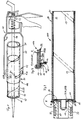
- the cartridge gun has at its front end an annular body 43 against which the muzzle closure 10 of the cartridge is supported on the edge, while the piston 42 is driven into the cartridge and drives a hollow piston-shaped sealing element 44 in the direction of the muzzle closure 10 and thereby the Drives cartridge contents out of the cartridge via an orifice 15.
- the mouth closure 10 and the sealing element 44 according to FIG. 5 are preferably identical on their surfaces to be facing one another, preferably domed, shaped (male / female).
- a novel cartridge pistol 40 modified in the area of the ring body 43, is used in the ring body 43 in accordance with the exemplary embodiment shown in FIGS two ring body halves 43A and 43B is divided. These two halves of the ring body are held together during normal use for emptying the cartridge by a simple securing element (not shown); If this securing element is removed, the ring body halves can be spaced apart from one another by means of their resilient retaining brackets 45 so that the mouth closure 10 of the packaging container 100 fits through them.
- the ring body halves 43A and 43B which are provided with gripping elements 41 on their radially inward side, are pressed slightly together, for example with one hand, so that the gripping elements 41 dig into the outer sleeve 21. If the piston 42 is now pressed further forward, the entire inner sleeve 22 together with the muzzle closure 10 serving as a handle and the sealing element 44 are advanced with respect to the outer sleeve 21, as shown.
- the piston rod 46 of the cartridge gun 40 preferably has a somewhat longer length than usual. This displacement process can already be stopped in the relative position between the inner sleeve and the outer sleeve shown in FIG. 1, because the two sleeves can then be easily separated from one another by further pulling apart. Guide elements 51 (FIG. 4) facilitate the handling of the ring body halves.
- both the mouth closure 10 and the mouthpiece 15 provided on it and the sealing element 44 consist of one and the same material, which is preferably made of the material the inner sleeve 22 is identical (Fig. 5). In this way, only two materials are used for the packaging container and can be recycled separately, apart from possibly existing, vanishingly small amounts of heat-sealable plastic.
- a film-like material can also be considered as the mouth closure 10, in particular a film material which, with that of the inner sleeve 22, is made of the same material, preferably of aluminum, whereby - again preferably - both the mouth closure and the inner sleeve are coated on their sides facing the inside of the container with a heat-weldable plastic or both are constructed from such a material.
- a film-like material can also be considered as the mouth closure 10, in particular a film material which, with that of the inner sleeve 22, is made of the same material, preferably of aluminum, whereby - again preferably - both the mouth closure and the inner sleeve are coated on their sides facing the inside of the container with a heat-weldable plastic or both are constructed from such a material.
- the inner sleeve 22 and the mouth closure 10 each consist of an aluminum foil layer 22A and a plastic surface coating 22B, preferably of polyethylene.
- the mouth closure 10 is provided with a sufficient excess so that a flange 10A covering the end face of the sleeve body 20 can form, which is held in position by a resiliently pressable ring 33 before the metal body 30 is inserted into the free sleeve end.
- the ring 33 is displaceably supported by guide rods 34 in guide bores 35 of the metal body 30 against the pressure of springs 36 and arranged in such a way that the ring 33 on the flange 10A first comes to the holding / pressing contact at the front end of the sleeve body 20 before the Ring contour 31 of the metal body 30 slides into the sleeve end.
- a known protective cap 60 shown in dashed lines in FIG. 6, made of plastic, metal or the like, can be used as a further, mechanically acting protective agent on the completely closed sleeve end be postponed.
- the film-like inner sleeve can also be produced from materials other than aluminum, such as parchment, paper or other film-like materials.
- the separate sleeves 21 and 22 can then be sent separately for recycling or disposal. If it is not possible to recycle the inner sleeve 20, in particular because of its contamination, it can be compressed to a fraction of its original volume, so that the volume to be fed to a hazardous waste landfill can be considerably reduced.
- the outer sleeve 21 is provided with at least one axially extending perforation 115 which, after emptying the packaging container, allows the independent outer sleeve 21 to be broken open and the inner sleeve 22 to be removed without being destroyed.
- a perforation 115 can easily be introduced before the packaging container is labeled.
Landscapes
- Engineering & Computer Science (AREA)
- Mechanical Engineering (AREA)
- Making Paper Articles (AREA)
- Packages (AREA)
- Cartons (AREA)
- Containers And Plastic Fillers For Packaging (AREA)
- Wrappers (AREA)
- Tubes (AREA)
Applications Claiming Priority (2)
| Application Number | Priority Date | Filing Date | Title |
|---|---|---|---|
| DE4123743 | 1991-07-17 | ||
| DE19914123743 DE4123743A1 (de) | 1991-07-17 | 1991-07-17 | Huelsenfoermiger verpackungsbehaelter aus mehrschichtmaterial sowie verfahren und vorrichtung zum herstellen eines derartigen verpackungsbehaelters |
Publications (1)
| Publication Number | Publication Date |
|---|---|
| EP0524514A1 true EP0524514A1 (fr) | 1993-01-27 |
Family
ID=6436398
Family Applications (3)
| Application Number | Title | Priority Date | Filing Date |
|---|---|---|---|
| EP19920110915 Expired - Lifetime EP0523433B1 (fr) | 1991-07-17 | 1992-06-27 | Procédé de fabrication d'un récipient d'emballage cylindrique |
| EP92914588A Revoked EP0596906B1 (fr) | 1991-07-17 | 1992-07-11 | Recipient d'emballage en forme de douille en materiau multicouche, ainsi que procede et dispositif pour la fabrication d'un tel recipient d'emballage |
| EP19920111864 Withdrawn EP0524514A1 (fr) | 1991-07-17 | 1992-07-11 | Récipient d'emballage tubulaire multicouche et procédé et dispositif pour la fabrication d'un tel récipient |
Family Applications Before (2)
| Application Number | Title | Priority Date | Filing Date |
|---|---|---|---|
| EP19920110915 Expired - Lifetime EP0523433B1 (fr) | 1991-07-17 | 1992-06-27 | Procédé de fabrication d'un récipient d'emballage cylindrique |
| EP92914588A Revoked EP0596906B1 (fr) | 1991-07-17 | 1992-07-11 | Recipient d'emballage en forme de douille en materiau multicouche, ainsi que procede et dispositif pour la fabrication d'un tel recipient d'emballage |
Country Status (9)
| Country | Link |
|---|---|
| EP (3) | EP0523433B1 (fr) |
| JP (1) | JPH07500074A (fr) |
| CN (1) | CN1068791A (fr) |
| AT (2) | ATE135986T1 (fr) |
| AU (1) | AU2312292A (fr) |
| DE (3) | DE4123743A1 (fr) |
| IL (1) | IL102526A0 (fr) |
| WO (1) | WO1993001994A1 (fr) |
| ZA (1) | ZA925188B (fr) |
Cited By (2)
| Publication number | Priority date | Publication date | Assignee | Title |
|---|---|---|---|---|
| NL9300505A (nl) * | 1993-03-22 | 1994-10-17 | Theodorus Johannes Maria De Ru | Verpakkingssysteem, in het bijzonder bestemd voor de grafische industrie. |
| WO1996031413A1 (fr) * | 1995-04-07 | 1996-10-10 | Henkel Kommanditgesellschaft Auf Aktien | Cartouche |
Families Citing this family (3)
| Publication number | Priority date | Publication date | Assignee | Title |
|---|---|---|---|---|
| DE19809255B4 (de) * | 1998-03-05 | 2004-09-16 | Kkt Kaller Kunststoff Technik Gmbh | Kartusche zur Aufnahme einer viskosen oder pastösen Masse |
| US6358343B1 (en) * | 1999-12-22 | 2002-03-19 | C. Winfield Scott | Method for manufacturing plastic drums |
| DE10006288A1 (de) * | 2000-02-14 | 2001-08-16 | Vg Nicolaus Gmbh | Zylinderförmige Verpackung für pastöse Füllgüter |
Citations (5)
| Publication number | Priority date | Publication date | Assignee | Title |
|---|---|---|---|---|
| GB491904A (en) * | 1936-08-07 | 1938-09-12 | Dobeckmun Co | Improvements in or relating to cartons or containers for oil |
| DE1134271B (de) * | 1960-03-21 | 1962-08-02 | R C Can Company | Verfahren zur Herstellung eines Behaelters mit teleskopartig aufsitzendem Deckel undVorrichtung zur Durchfuehrung dieses Verfahrens |
| FR2218192A1 (fr) * | 1973-01-04 | 1974-09-13 | Lincrusta | |
| US4299329A (en) * | 1979-07-09 | 1981-11-10 | Taniuchi Keiji | Extrusion cover for containers |
| EP0113160A1 (fr) * | 1982-12-03 | 1984-07-11 | Ajinomoto Co., Inc. | Boîte de conserves en plastique |
Family Cites Families (3)
| Publication number | Priority date | Publication date | Assignee | Title |
|---|---|---|---|---|
| DE3237634A1 (de) * | 1982-10-11 | 1984-04-12 | Buck Chemisch-Technische Werke Gmbh & Co, 8230 Bad Reichenhall | Vakuumdichte dose |
| EP0151922A3 (fr) * | 1984-01-11 | 1986-03-05 | Teroson GmbH | Emballage en forme de sac tubulaire |
| CH681367A5 (fr) * | 1990-09-12 | 1993-03-15 | Sandherr Packungen Ag |
-
1991
- 1991-07-17 DE DE19914123743 patent/DE4123743A1/de not_active Withdrawn
-
1992
- 1992-06-27 DE DE59205818T patent/DE59205818D1/de not_active Expired - Fee Related
- 1992-06-27 EP EP19920110915 patent/EP0523433B1/fr not_active Expired - Lifetime
- 1992-06-27 AT AT92110915T patent/ATE135986T1/de not_active IP Right Cessation
- 1992-07-10 ZA ZA925188A patent/ZA925188B/xx unknown
- 1992-07-11 EP EP92914588A patent/EP0596906B1/fr not_active Revoked
- 1992-07-11 JP JP5502561A patent/JPH07500074A/ja active Pending
- 1992-07-11 WO PCT/EP1992/001570 patent/WO1993001994A1/fr not_active Application Discontinuation
- 1992-07-11 AT AT92914588T patent/ATE163621T1/de not_active IP Right Cessation
- 1992-07-11 AU AU23122/92A patent/AU2312292A/en not_active Abandoned
- 1992-07-11 EP EP19920111864 patent/EP0524514A1/fr not_active Withdrawn
- 1992-07-11 DE DE59209220T patent/DE59209220D1/de not_active Revoked
- 1992-07-16 IL IL102526A patent/IL102526A0/xx unknown
- 1992-07-16 CN CN92105780A patent/CN1068791A/zh active Pending
Patent Citations (5)
| Publication number | Priority date | Publication date | Assignee | Title |
|---|---|---|---|---|
| GB491904A (en) * | 1936-08-07 | 1938-09-12 | Dobeckmun Co | Improvements in or relating to cartons or containers for oil |
| DE1134271B (de) * | 1960-03-21 | 1962-08-02 | R C Can Company | Verfahren zur Herstellung eines Behaelters mit teleskopartig aufsitzendem Deckel undVorrichtung zur Durchfuehrung dieses Verfahrens |
| FR2218192A1 (fr) * | 1973-01-04 | 1974-09-13 | Lincrusta | |
| US4299329A (en) * | 1979-07-09 | 1981-11-10 | Taniuchi Keiji | Extrusion cover for containers |
| EP0113160A1 (fr) * | 1982-12-03 | 1984-07-11 | Ajinomoto Co., Inc. | Boîte de conserves en plastique |
Cited By (2)
| Publication number | Priority date | Publication date | Assignee | Title |
|---|---|---|---|---|
| NL9300505A (nl) * | 1993-03-22 | 1994-10-17 | Theodorus Johannes Maria De Ru | Verpakkingssysteem, in het bijzonder bestemd voor de grafische industrie. |
| WO1996031413A1 (fr) * | 1995-04-07 | 1996-10-10 | Henkel Kommanditgesellschaft Auf Aktien | Cartouche |
Also Published As
| Publication number | Publication date |
|---|---|
| DE59209220D1 (de) | 1998-04-09 |
| ATE163621T1 (de) | 1998-03-15 |
| CN1068791A (zh) | 1993-02-10 |
| EP0523433A1 (fr) | 1993-01-20 |
| EP0596906B1 (fr) | 1998-03-04 |
| IL102526A0 (en) | 1993-01-14 |
| DE4123743A1 (de) | 1993-01-21 |
| EP0523433B1 (fr) | 1996-03-27 |
| WO1993001994A1 (fr) | 1993-02-04 |
| EP0596906A1 (fr) | 1994-05-18 |
| DE59205818D1 (de) | 1996-05-02 |
| ATE135986T1 (de) | 1996-04-15 |
| AU2312292A (en) | 1993-02-23 |
| ZA925188B (en) | 1994-02-10 |
| JPH07500074A (ja) | 1995-01-05 |
Similar Documents
| Publication | Publication Date | Title |
|---|---|---|
| EP1644145B1 (fr) | Procede et dispositif pour produire un corps de boite-boisson, ainsi que corps de boite-boisson | |
| DE60007963T2 (de) | Behälter zur Aufnahme von zerbrechlichen Gegenständen sowie Verfahren zur Herstellung eines solchen Behälters | |
| EP4249230A2 (fr) | Procédé de fabrication d'une boîte résistante à la pression | |
| DE2541912C2 (de) | Behälter, insbesondere Verpackungsbehälter, sowie Verfahren zum Herstellen eines solchen Behälters und Vorrichtung zum Durchführen des Verfahrens | |
| DE2249865A1 (de) | Vorrichtung und verfahren zur herstellung eines behaelters aus einer materialbahn | |
| DE3322977A1 (de) | Papierbehaelter fuer heiss abfuellbare fluessigkeiten | |
| WO1995009111A1 (fr) | Recipient en matiere thermoplastique et son procede de production | |
| DE2826680C2 (de) | Zusammendrückbarer Spendbehälter und Verfahren zu seiner Herstellung | |
| EP0524514A1 (fr) | Récipient d'emballage tubulaire multicouche et procédé et dispositif pour la fabrication d'un tel récipient | |
| DE2720907C2 (de) | Tubenartiger Behälter und Verfahren zu seiner Herstellung | |
| EP1882637B1 (fr) | Récipient d'emballage | |
| AT521461B1 (de) | Druckfeste Dose | |
| EP0447997A2 (fr) | Emballage du type boîte pour produits pouvant s'écouler et procédé pour sa fabrication | |
| DE202006007686U1 (de) | Vorrichtung zur Sicherung rollbarer Transportgüter auf einer Transport-Palette | |
| DE60302795T2 (de) | Verfahren und vorrichtung zum herstellen einer röhrförmigen verpackung | |
| EP1153837A1 (fr) | Méthode et dispositif pour l'application d'étiquettes tubulaires sur conteneurs | |
| AT506749B1 (de) | Verfahren zur herstellung eines kombi-verpackungsbehälters | |
| CH704798A2 (de) | Verfahren und Vorrichtung zum Herstellen von Dosenkörpern sowie Dosenkörper. | |
| DE102011103543B4 (de) | Verfahren zur Herstellung einer Tube | |
| DE2243958C3 (de) | Verfahren und Vorrichtung zum Herstellen dünnwandiger Behälter | |
| DE1561546C (de) | Behälter mit einem Aufnahmeteil und einem Stützteil sowie Verfahren zu dessen Herstellung und Werkzeug zur Durchführung des Verfahrens | |
| DE102021116490A1 (de) | Kartusche mit einem als Folie ausgebildeten Kopfstück und Stützhülse | |
| DE1782596C3 (de) | Verpackungsbehälter mit einem Behälterkörper und einer in diesen eingesetzten Auskleidung sowie Verfahren und Vorrichtung zu dessen Herstellung | |
| DE1944490C3 (de) | Stapelfähige, formbeständige Konservendose | |
| AT526366A1 (de) | Zuschnitt, sowie aus einem Zuschnitt gebildetes manschettenförmiges Außenteil zum Ummanteln eines becherförmigen Innenbehälters, sowie Kombi-Verpackungsbehälter |
Legal Events
| Date | Code | Title | Description |
|---|---|---|---|
| PUAI | Public reference made under article 153(3) epc to a published international application that has entered the european phase |
Free format text: ORIGINAL CODE: 0009012 |
|
| AK | Designated contracting states |
Kind code of ref document: A1 Designated state(s): PT |
|
| STAA | Information on the status of an ep patent application or granted ep patent |
Free format text: STATUS: THE APPLICATION IS DEEMED TO BE WITHDRAWN |
|
| 18D | Application deemed to be withdrawn |
Effective date: 19930728 |
|
| RIN1 | Information on inventor provided before grant (corrected) |
Inventor name: FORSTMANN, FRANK Inventor name: KIRCHBERG, KARL |