EP0447997A2 - Emballage du type boîte pour produits pouvant s'écouler et procédé pour sa fabrication - Google Patents
Emballage du type boîte pour produits pouvant s'écouler et procédé pour sa fabrication Download PDFInfo
- Publication number
- EP0447997A2 EP0447997A2 EP91104085A EP91104085A EP0447997A2 EP 0447997 A2 EP0447997 A2 EP 0447997A2 EP 91104085 A EP91104085 A EP 91104085A EP 91104085 A EP91104085 A EP 91104085A EP 0447997 A2 EP0447997 A2 EP 0447997A2
- Authority
- EP
- European Patent Office
- Prior art keywords
- neck part
- membrane
- collar
- closure
- closure membrane
- Prior art date
- Legal status (The legal status is an assumption and is not a legal conclusion. Google has not performed a legal analysis and makes no representation as to the accuracy of the status listed.)
- Withdrawn
Links
Images


Classifications
-
- B—PERFORMING OPERATIONS; TRANSPORTING
- B65—CONVEYING; PACKING; STORING; HANDLING THIN OR FILAMENTARY MATERIAL
- B65D—CONTAINERS FOR STORAGE OR TRANSPORT OF ARTICLES OR MATERIALS, e.g. BAGS, BARRELS, BOTTLES, BOXES, CANS, CARTONS, CRATES, DRUMS, JARS, TANKS, HOPPERS, FORWARDING CONTAINERS; ACCESSORIES, CLOSURES, OR FITTINGS THEREFOR; PACKAGING ELEMENTS; PACKAGES
- B65D83/00—Containers or packages with special means for dispensing contents
- B65D83/14—Containers or packages with special means for dispensing contents for delivery of liquid or semi-liquid contents by internal gaseous pressure, i.e. aerosol containers comprising propellant for a product delivered by a propellant
- B65D83/38—Details of the container body
-
- B—PERFORMING OPERATIONS; TRANSPORTING
- B05—SPRAYING OR ATOMISING IN GENERAL; APPLYING FLUENT MATERIALS TO SURFACES, IN GENERAL
- B05B—SPRAYING APPARATUS; ATOMISING APPARATUS; NOZZLES
- B05B11/00—Single-unit hand-held apparatus in which flow of contents is produced by the muscular force of the operator at the moment of use
- B05B11/0005—Components or details
- B05B11/0037—Containers
- B05B11/0038—Inner container disposed in an outer shell or outer casing
-
- B—PERFORMING OPERATIONS; TRANSPORTING
- B05—SPRAYING OR ATOMISING IN GENERAL; APPLYING FLUENT MATERIALS TO SURFACES, IN GENERAL
- B05B—SPRAYING APPARATUS; ATOMISING APPARATUS; NOZZLES
- B05B11/00—Single-unit hand-held apparatus in which flow of contents is produced by the muscular force of the operator at the moment of use
- B05B11/0005—Components or details
- B05B11/0037—Containers
-
- B—PERFORMING OPERATIONS; TRANSPORTING
- B05—SPRAYING OR ATOMISING IN GENERAL; APPLYING FLUENT MATERIALS TO SURFACES, IN GENERAL
- B05B—SPRAYING APPARATUS; ATOMISING APPARATUS; NOZZLES
- B05B11/00—Single-unit hand-held apparatus in which flow of contents is produced by the muscular force of the operator at the moment of use
- B05B11/01—Single-unit hand-held apparatus in which flow of contents is produced by the muscular force of the operator at the moment of use characterised by the means producing the flow
- B05B11/10—Pump arrangements for transferring the contents from the container to a pump chamber by a sucking effect and forcing the contents out through the dispensing nozzle
- B05B11/1042—Components or details
- B05B11/1043—Sealing or attachment arrangements between pump and container
- B05B11/1046—Sealing or attachment arrangements between pump and container the pump chamber being arranged substantially coaxially to the neck of the container
- B05B11/1047—Sealing or attachment arrangements between pump and container the pump chamber being arranged substantially coaxially to the neck of the container the pump being preassembled as an independent unit before being mounted on the container
-
- B—PERFORMING OPERATIONS; TRANSPORTING
- B05—SPRAYING OR ATOMISING IN GENERAL; APPLYING FLUENT MATERIALS TO SURFACES, IN GENERAL
- B05B—SPRAYING APPARATUS; ATOMISING APPARATUS; NOZZLES
- B05B11/00—Single-unit hand-held apparatus in which flow of contents is produced by the muscular force of the operator at the moment of use
- B05B11/01—Single-unit hand-held apparatus in which flow of contents is produced by the muscular force of the operator at the moment of use characterised by the means producing the flow
- B05B11/10—Pump arrangements for transferring the contents from the container to a pump chamber by a sucking effect and forcing the contents out through the dispensing nozzle
- B05B11/1001—Piston pumps
Definitions
- the invention relates to a can-like packaging for flowable products, consisting of a sleeve, a bottom closing one end and a closing membrane closing its other end, wherein first the sleeve and the bottom are formed from a paper or cardboard composite and this and the closure membrane inside are provided with a sealable plastic layer, by means of which they can be tightly connected to one another.
- the invention is also directed to a method for producing the aforementioned packaging.
- Packaging of the aforementioned construction is used today in a variety of ways, for example in the food sector for instant powder, jams, etc. They consist predominantly of paper or cardboard composite material and are usually only provided with a metal foil or a metal sack for the necessary liquid and gas tightness . This makes these packaging different from pure plastic packaging usable in an environmentally friendly way. The use of energy for their production is also very low, especially since the paper or cardboard composite can come from recycling processes. The pure mass use is also relatively low.
- the sealing membrane is broken open to remove the filling material.
- a further plastic cover must then generally be provided, with which the opened packaging can be closed.
- the disadvantage here is that such a cover usually does not provide a tight seal.
- the aim is in particular to attach the removal device, for example an atomizing pump with an atomizing head, to the sleeve so that it can be reused, while the packaging is thrown away after emptying and the removal device is placed on a new packaging which is closed by the closure membrane. after they have been separated.
- the removal device for example an atomizing pump with an atomizing head
- the invention is based on the object of designing a packaging of the structure mentioned at the outset, which therefore consists predominantly of paper or cardboard composite, in such a way that conventional closures or removal devices, as are known for plastic, glass or metal packaging, can be used, especially after opening, a tight seal is possible.
- the closure membrane has an opening and on the outside also has a sealable plastic layer and that a neck part made of dimensionally stable plastic is provided, which rests on the outside with a collar of the closure membrane and whose opening engages with a sleeve-like approach, and that the approach is formed into a collar lying on the inside of the membrane and at least one of the two collars is welded to the plastic layer of the closure membrane.
- a packaging consisting predominantly of paper or cardboard which, owing to the neck part used, allows practically every conventional option for tight sealing, the use of dispensers, atomizers or the like.
- the plastic component which is undesirable for environmental reasons, is limited to a minimum, namely the neck part. Sealing the neck part by means of one of its collars with the closure membrane results in a gas and liquid-tight connection between the neck part and the closure membrane.
- the neck part itself offers the possibility of tight attachment of screw, plug, snap closures or the like. These can only be closures or also closure parts from dispensers, atomizers or the like, which can be reusably placed on refill packs of the same construction.
- both collars are sealed with the plastic layers of the closure membrane, which ensures an increased sealing time.
- This version is particularly suitable for large-volume packaging with a correspondingly large sealing membrane, since this is stiffened in the middle by the neck part.
- the invention is also applicable to any packaging cross-section (round, non-circular, polygonal or the like).
- the neck portion is preferably formed into the collar by means of ultrasound, and the collar can also be welded to the plastic layers of the closure membrane by means of ultrasound. It is therefore particularly possible to carry out both the forming and the sealing in a single operation and in one tool.
- the invention also opens up the possibility of also producing the closure membrane from a paper or cardboard composite, so that the proportion of environmentally friendly and energy-saving materials is further increased.
- the neck part can have an external or internal thread or else a latching or plug-in profile for a closure, a removal device or the like. Furthermore, it can have sealing surfaces or circumferential sealing edges in a manner customary in the case of plastics, in order to achieve a tight seal for the filling material or a limited pressure-resistant design.
- the outer end face of the neck part lies in or below the plane of the end face of the sleeve, so that this end face does not protrude.
- a further preferred embodiment is characterized in that the internally threaded neck part has an outer diameter which is smaller than the inner diameter of the opening of the closure membrane and projects into the container and that the collar which lies on the outside of the closure membrane has the sleeve-shaped projection which passes through the opening and is formed into the inner collar.
- This design allows the internal thread to be drawn into the interior of the container, making the outer area of the neck part very short and still maintaining the necessary load-bearing capacity on the thread.
- Such an embodiment cannot be achieved at all with conventional plastic packaging which is produced by the blowing process.
- the neck part has at least two substantially radially extending lugs resting on the closure membrane, which are provided with catch-like undercuts, and that the closure or the removal device is provided with resiliently engaging lugs.
- the aforementioned embodiment gives the possibility of placing a dispenser, atomizer or the like on the neck part by a simple latching process.
- the locking can be done with such a pretension that a perfect seal on the neck part is possible.
- the neck part can be sealed with a membrane at its opening.
- the packaging can be used as a refill for a dispenser, atomizer or the like bought by the customer with the first packaging.
- a particularly simple and inexpensive method for producing the packaging according to the invention is based on the prior art known from DE-A-28 46 755 and is characterized by the features characterized in claims 13 to 16.
- the sealing membrane provided with the neck part according to the inventive method is then connected to the sleeve in a conventional manner.
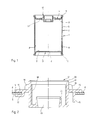
- Figure 1 shows a can-like package 2 in a cylindrical shape. But it can also be oval, non-circular or polygonal.
- the packaging consists of a sleeve 2, a bottom 3 and a sealing membrane 4.
- the bottom 3 and the closure membrane 4 are designed as a deep-drawing line and placed on the end faces of the sleeve 2.
- the sleeve 2 consists of a paper or cardboard composite 5.
- the bottom 3 can have a cardboard composite 6
- the closure membrane 4 can have a cardboard composite 7.
- the wall thickness of the cardboard composite 5 of the sleeve 2, and possibly also the cardboard composite 6 of the base 3, will be greater than that of the cardboard composite 7 of the sealing membrane 4.
- the sleeve 2, the base 3 and the sealing membrane 4, preferably on the inside have a Metal foil or metal coating to ensure a gas and liquid tight execution.
- the sleeve 2, the bottom 3 and the closure membrane 4 are provided with a sealable plastic coating 8.
- the closure membrane 4 also has a similar plastic coating on the outside.
- the bottom 3 and the closure membrane 4 are placed on their edge 9, 10 around the end face of the sleeve 2 and sealed to the sleeve in the entire edge area.
- the closure membrane 4 has a central opening 11 into which a neck part 12 is inserted.
- the neck part 12 serves to receive a closure, a removal device, e.g. a dispenser, atomizer or the like.
- FIG. 2 shows the neck part 12 according to FIG. 1 enlarged, the neck part 12 being shown in the right part of the illustration before being fastened to the closure membrane 4 and in the left part of the illustration after being fastened.
- the neck part 12 has a cylindrical center piece 13 and a collar 14 formed thereon, which lies on the outside of the closure membrane 4. Furthermore, the neck part 12 has a sleeve-like extension 15, which extends through the opening 11 and projects beyond the closure membrane 4 on the inside.
- the Collar can optionally be formed on the central piece 13 radially extending ribs 16.
- the cylindrical extension 15 is molded onto the inside of the closure membrane 4 to form an inner collar 17. This can be done by applying heat or preferably by ultrasound.
- the deformed collar 17 is then sealed in the same technique, that is, preferably by ultrasound, with the plastic coating 8 on the inside of the closure membrane 4.
- the outer collar 14 can also be sealed with the closure membrane 4 by also having a corresponding plastic coating on the outside. In this way, a hermetic seal between the neck part 12 and the closure membrane 4 can be achieved.
- the neck part 12 has an internal thread 18. Furthermore, the middle piece 13 is drawn in at its inner end and provided with a cylindrical projection 19 which in turn projects upwards.
- This embodiment of the neck part 12 is particularly suitable for receiving an atomizer head with a hand pump, by means of which liquid filling material, for example, can be removed from the packaging 1 and atomized via an immersion tube.
- the neck part 12 has on its outer end face a sealing edge 20 against which, for example, a cap of the atomizer seals.
- the neck part 12, for example on the cylindrical extension 19, can have a further sealing surface 21, against which, for example, a round cord seal or the like rests on the atomizer head.
- FIG. 3 shows an embodiment of an atomizer 22 which is placed on a can-like packaging 1.
- the packaging has, as in the exemplary embodiment according to FIG. 1 a sleeve 2, a bottom 3 and a sealing membrane 4.
- the neck part 12 is inserted into the closure membrane 4 and sealed to the closure membrane 4 with its inner collar 17.
- the neck part 12 has essentially radially extending projections 23 on the outside of the closure membrane 4, which are provided with catch-like undercuts 24.
- mutually opposite handles 25 are arranged radially resiliently, which engage undercuts 24 on the neck part 12 with lugs 26.
- the atomizer 22 is put on from above and the lugs 26 snap into the undercuts 24 under slight pressure.
- the atomizer 22 has a cap 27 which seals under the clamping action generated by the lugs 26 on the undercuts 24 by means of a round cord ring 28 against the inner edge of the neck part 12.
- FIG. 4 shows the process steps for producing the connection between neck part 12 and closure membrane 4.
- the closure membrane 4 consists of a cardboard composite 30 and a coating 31, 32 on both sides made of plastic, for example PE.
- the neck part which is also made of plastic, for example PE, by injection molding, has a molded-on shoulder, for example a collar 33 - similar to the collar 14 according to FIG. 2.
- the closure membrane 4 is plugged with its opening 11 onto the neck part 12 from one end face thereof.
- the neck part is placed with its collar 33 on an abutment 34 (Fig. 4b).
- the neck part is then thermally expanded from the front face.
- the sonotrode 35 of an ultrasonic welding device which has a head 36 which partially penetrates into the neck part, is preferably used for this purpose.
- the sonotrode 35 By lowering the sonotrode 35 (FIG. 4c), the upper region of the neck part is displaced further and further and finally against the closure membrane 4 is formed (Fig. 4d).
- the prefabricated collar 33 and the molded collar 37 are sealed with the coating 31, 32 of the closure membrane by ultrasound, and thus a moisture and gas-tight connection of the neck part 12 and the closure membrane 4 is produced.
Applications Claiming Priority (2)
| Application Number | Priority Date | Filing Date | Title |
|---|---|---|---|
| DE4009397 | 1990-03-23 | ||
| DE4009397A DE4009397A1 (de) | 1990-03-23 | 1990-03-23 | Dosenartige verpackung fuer fliessfaehige produkte |
Publications (2)
| Publication Number | Publication Date |
|---|---|
| EP0447997A2 true EP0447997A2 (fr) | 1991-09-25 |
| EP0447997A3 EP0447997A3 (en) | 1993-02-03 |
Family
ID=6402927
Family Applications (1)
| Application Number | Title | Priority Date | Filing Date |
|---|---|---|---|
| EP19910104085 Withdrawn EP0447997A3 (en) | 1990-03-23 | 1991-03-16 | Can-like package for flowable products and method for its manufacture |
Country Status (2)
| Country | Link |
|---|---|
| EP (1) | EP0447997A3 (fr) |
| DE (1) | DE4009397A1 (fr) |
Cited By (2)
| Publication number | Priority date | Publication date | Assignee | Title |
|---|---|---|---|---|
| EP0546898A1 (fr) * | 1991-12-13 | 1993-06-16 | Conceptair B.V. | Dispositif rechargeable de pulvérisation d'une substance fluide |
| IT202000027618A1 (it) * | 2020-11-18 | 2022-05-18 | Lumson Spa | Dispositivo di erogazione di una sostanza fluida |
Families Citing this family (6)
| Publication number | Priority date | Publication date | Assignee | Title |
|---|---|---|---|---|
| DE19502992A1 (de) * | 1995-02-01 | 1996-08-08 | Brain Power Consulting Gmbh | Verfahren zum Herstellen von Hohlkörpern und Hohlkörper nach diesem Verfahren |
| ATE250439T1 (de) * | 1995-04-14 | 2003-10-15 | Smithkline Beecham Corp | Dosierinhalator für salmeterol |
| JPH11503352A (ja) | 1995-04-14 | 1999-03-26 | グラクソ、ウェルカム、インコーポレーテッド | プロピオン酸フルチカゾン用計量投与用吸入器 |
| JP3573213B2 (ja) * | 1995-04-14 | 2004-10-06 | グラクソ、ウェルカム、インコーポレーテッド | ベクロメタゾンジプロピオネート用計量投与用吸入器 |
| CZ292578B6 (cs) | 1995-04-14 | 2003-10-15 | Glaxo Wellcome Inc. | Inhalátor, inhalační systém |
| US8227027B2 (en) | 2007-12-07 | 2012-07-24 | Presspart Gmbh & Co. Kg | Method for applying a polymer coating to an internal surface of a container |
Citations (3)
| Publication number | Priority date | Publication date | Assignee | Title |
|---|---|---|---|---|
| US2215268A (en) * | 1938-07-07 | 1940-09-17 | Himmer Vitalis | Container |
| DE3526682A1 (de) * | 1985-07-25 | 1987-01-29 | Noefa Gmbh | Oeffnungsteil fuer einen behaelter, verfahren zur herstellung eines behaelters und vorrichtung zur durchfuehrung des verfahrens |
| DE3842909A1 (de) * | 1987-12-24 | 1989-07-06 | Weidenhammer Packungen | Verpackung zur abgabe fliessfaehiger produkte |
Family Cites Families (12)
| Publication number | Priority date | Publication date | Assignee | Title |
|---|---|---|---|---|
| US2522772A (en) * | 1947-03-18 | 1950-09-19 | Cordelia P Benjamin | Container |
| DE1810211U (de) * | 1960-01-26 | 1960-04-21 | F W Oventrop Arn Sohn K G | Im einfuellstutzen eines fasses befestigbare pumpe. |
| US3072312A (en) * | 1961-02-10 | 1963-01-08 | Cleveland Container Corp | Fluid container |
| GB1417397A (en) * | 1972-02-17 | 1975-12-10 | Hoechst Uk Ltd | Adapters for containers |
| IT1097763B (it) * | 1978-07-28 | 1985-08-31 | Cartotecnica Poligrafica A & G | Fustino o simile recipiente, specialmente destinato a contenere materiale folverulento, quali detersivi cd altro |
| DE2849755A1 (de) * | 1978-11-16 | 1980-05-29 | Eckes Fa Peter | Vorrichtung zum wiederholten oeffnen und schliessen einer oeffnung in einem deckel eines behaelters |
| NZ200030A (en) * | 1981-03-30 | 1985-07-12 | Waddington & Duval Ltd | Dispensing valve breaks seal on first depression |
| EP0318465B1 (fr) * | 1985-03-14 | 1992-01-02 | MegaPlast Dosiersysteme GmbH & Co. | Pompe doseuse avec soufflet de pompage pour bouteilles ou analogues |
| GB2187712B (en) * | 1986-03-11 | 1990-05-23 | Tetra Pak Finance & Trading | Fluid pack and process for the production therof |
| DE3832412C2 (de) * | 1987-09-24 | 2002-10-02 | Dainippon Printing Co Ltd | Flüssigkeitsdichter Pappbehälter mit einer Flüssigkeitsausgießvorrichtung |
| DE8814473U1 (fr) * | 1988-11-19 | 1989-03-30 | Sieger Plastic Gmbh, 5160 Dueren, De | |
| DE8907247U1 (fr) * | 1989-06-14 | 1989-08-24 | Bauer, Heinz-Dieter, 4286 Suedlohn, De |
-
1990
- 1990-03-23 DE DE4009397A patent/DE4009397A1/de not_active Withdrawn
-
1991
- 1991-03-16 EP EP19910104085 patent/EP0447997A3/de not_active Withdrawn
Patent Citations (3)
| Publication number | Priority date | Publication date | Assignee | Title |
|---|---|---|---|---|
| US2215268A (en) * | 1938-07-07 | 1940-09-17 | Himmer Vitalis | Container |
| DE3526682A1 (de) * | 1985-07-25 | 1987-01-29 | Noefa Gmbh | Oeffnungsteil fuer einen behaelter, verfahren zur herstellung eines behaelters und vorrichtung zur durchfuehrung des verfahrens |
| DE3842909A1 (de) * | 1987-12-24 | 1989-07-06 | Weidenhammer Packungen | Verpackung zur abgabe fliessfaehiger produkte |
Cited By (6)
| Publication number | Priority date | Publication date | Assignee | Title |
|---|---|---|---|---|
| EP0546898A1 (fr) * | 1991-12-13 | 1993-06-16 | Conceptair B.V. | Dispositif rechargeable de pulvérisation d'une substance fluide |
| FR2684901A1 (fr) * | 1991-12-13 | 1993-06-18 | Conceptair Anstalt | Procede et dispositif evitant la formation de poches gazeuses dans un reservoir pour un produit fluide destine a etre pulverise ou distribue sans reprise d'air. |
| US5417258A (en) * | 1991-12-13 | 1995-05-23 | Conceptair Anstalt | Rechargeable device for spraying a fluid |
| IT202000027618A1 (it) * | 2020-11-18 | 2022-05-18 | Lumson Spa | Dispositivo di erogazione di una sostanza fluida |
| EP4000746A1 (fr) * | 2020-11-18 | 2022-05-25 | Lumson S.p.A. | Dispositif de distribution de substance fluide |
| US11759809B2 (en) | 2020-11-18 | 2023-09-19 | Lumson S.P.A. | Fluid substance dispensing device |
Also Published As
| Publication number | Publication date |
|---|---|
| DE4009397A1 (de) | 1991-09-26 |
| EP0447997A3 (en) | 1993-02-03 |
Similar Documents
| Publication | Publication Date | Title |
|---|---|---|
| EP0182094B1 (fr) | Procédé de fabrication d'un emballage muni d'une ouverture pouvant être refermée | |
| EP3140213B1 (fr) | Dispositif de mélange et de fermeture destiné à un récipient | |
| EP0101594B1 (fr) | Conditionnement à double contenance | |
| EP0114398B1 (fr) | Récipient compressible en forme de tube laminé | |
| EP2181051B1 (fr) | Dispositif distributeur | |
| EP0078403A2 (fr) | Récipient pour produits fluides muni d'un couvercle en matière plastique | |
| EP0675051B1 (fr) | Capuchon à vis avec un anneau soudé | |
| DE102007051980A1 (de) | Abgabevorrichtung | |
| DE2853958A1 (de) | Behaelterverschluss und verfahren zu seiner herstellung | |
| DE2262989A1 (de) | Roehrenfoermiger behaelter und verfahren zu seiner herstellung | |
| EP1027268B1 (fr) | Procede de production d'une bombe a aerosol presentant deux chambres, et dispositif pour mettre en oeuvre ledit procede | |
| EP0447997A2 (fr) | Emballage du type boîte pour produits pouvant s'écouler et procédé pour sa fabrication | |
| DE60106613T2 (de) | Tube mit grossem halsdurchmesser und starrem ansatzstück | |
| CH635792A5 (en) | Squeezable delivery container | |
| DE2724519C2 (de) | Zweikomponentenverpackung | |
| EP0079548A2 (fr) | Fermeture pour emballage | |
| DE4023274A1 (de) | Fuellstutzen fuer einen fluessigkeitsbehaelter | |
| WO2020025154A1 (fr) | Emballage de tube | |
| EP0659654B1 (fr) | Boîte d'emballage | |
| EP0731036B1 (fr) | Couvercle | |
| DE6903799U (de) | Verpackungsdose, insbesondere fuer gashatige fluessigkeiten | |
| EP0322709A2 (fr) | Emballage pour distribuer des produits fluides | |
| DE2253620A1 (de) | Zusammendrueckbarer behaelter | |
| DE19621617C2 (de) | Verfahren zur Herstellung eines Schraubdeckels | |
| WO1993001994A1 (fr) | Recipient d'emballage en forme de douille en materiau multicouche, ainsi que procede et dispositif pour la fabrication d'un tel recipient d'emballage |
Legal Events
| Date | Code | Title | Description |
|---|---|---|---|
| PUAI | Public reference made under article 153(3) epc to a published international application that has entered the european phase |
Free format text: ORIGINAL CODE: 0009012 |
|
| AK | Designated contracting states |
Kind code of ref document: A2 Designated state(s): CH DE FR GB IT LI |
|
| PUAL | Search report despatched |
Free format text: ORIGINAL CODE: 0009013 |
|
| AK | Designated contracting states |
Kind code of ref document: A3 Designated state(s): CH DE FR GB IT LI |
|
| 17P | Request for examination filed |
Effective date: 19930716 |
|
| 17Q | First examination report despatched |
Effective date: 19940930 |
|
| STAA | Information on the status of an ep patent application or granted ep patent |
Free format text: STATUS: THE APPLICATION IS DEEMED TO BE WITHDRAWN |
|
| 18D | Application deemed to be withdrawn |
Effective date: 19950213 |