EP0447997A2 - Can-like package for flowable products and method for its manufacture - Google Patents
Can-like package for flowable products and method for its manufacture Download PDFInfo
- Publication number
- EP0447997A2 EP0447997A2 EP91104085A EP91104085A EP0447997A2 EP 0447997 A2 EP0447997 A2 EP 0447997A2 EP 91104085 A EP91104085 A EP 91104085A EP 91104085 A EP91104085 A EP 91104085A EP 0447997 A2 EP0447997 A2 EP 0447997A2
- Authority
- EP
- European Patent Office
- Prior art keywords
- neck part
- membrane
- collar
- closure
- closure membrane
- Prior art date
- Legal status (The legal status is an assumption and is not a legal conclusion. Google has not performed a legal analysis and makes no representation as to the accuracy of the status listed.)
- Withdrawn
Links
Images


Classifications
-
- B—PERFORMING OPERATIONS; TRANSPORTING
- B65—CONVEYING; PACKING; STORING; HANDLING THIN OR FILAMENTARY MATERIAL
- B65D—CONTAINERS FOR STORAGE OR TRANSPORT OF ARTICLES OR MATERIALS, e.g. BAGS, BARRELS, BOTTLES, BOXES, CANS, CARTONS, CRATES, DRUMS, JARS, TANKS, HOPPERS, FORWARDING CONTAINERS; ACCESSORIES, CLOSURES, OR FITTINGS THEREFOR; PACKAGING ELEMENTS; PACKAGES
- B65D83/00—Containers or packages with special means for dispensing contents
- B65D83/14—Containers or packages with special means for dispensing contents for delivery of liquid or semi-liquid contents by internal gaseous pressure, i.e. aerosol containers comprising propellant for a product delivered by a propellant
- B65D83/38—Details of the container body
-
- B—PERFORMING OPERATIONS; TRANSPORTING
- B05—SPRAYING OR ATOMISING IN GENERAL; APPLYING FLUENT MATERIALS TO SURFACES, IN GENERAL
- B05B—SPRAYING APPARATUS; ATOMISING APPARATUS; NOZZLES
- B05B11/00—Single-unit hand-held apparatus in which flow of contents is produced by the muscular force of the operator at the moment of use
- B05B11/0005—Components or details
- B05B11/0037—Containers
- B05B11/0038—Inner container disposed in an outer shell or outer casing
-
- B—PERFORMING OPERATIONS; TRANSPORTING
- B05—SPRAYING OR ATOMISING IN GENERAL; APPLYING FLUENT MATERIALS TO SURFACES, IN GENERAL
- B05B—SPRAYING APPARATUS; ATOMISING APPARATUS; NOZZLES
- B05B11/00—Single-unit hand-held apparatus in which flow of contents is produced by the muscular force of the operator at the moment of use
- B05B11/0005—Components or details
- B05B11/0037—Containers
-
- B—PERFORMING OPERATIONS; TRANSPORTING
- B05—SPRAYING OR ATOMISING IN GENERAL; APPLYING FLUENT MATERIALS TO SURFACES, IN GENERAL
- B05B—SPRAYING APPARATUS; ATOMISING APPARATUS; NOZZLES
- B05B11/00—Single-unit hand-held apparatus in which flow of contents is produced by the muscular force of the operator at the moment of use
- B05B11/01—Single-unit hand-held apparatus in which flow of contents is produced by the muscular force of the operator at the moment of use characterised by the means producing the flow
- B05B11/10—Pump arrangements for transferring the contents from the container to a pump chamber by a sucking effect and forcing the contents out through the dispensing nozzle
- B05B11/1042—Components or details
- B05B11/1043—Sealing or attachment arrangements between pump and container
- B05B11/1046—Sealing or attachment arrangements between pump and container the pump chamber being arranged substantially coaxially to the neck of the container
- B05B11/1047—Sealing or attachment arrangements between pump and container the pump chamber being arranged substantially coaxially to the neck of the container the pump being preassembled as an independent unit before being mounted on the container
-
- B—PERFORMING OPERATIONS; TRANSPORTING
- B05—SPRAYING OR ATOMISING IN GENERAL; APPLYING FLUENT MATERIALS TO SURFACES, IN GENERAL
- B05B—SPRAYING APPARATUS; ATOMISING APPARATUS; NOZZLES
- B05B11/00—Single-unit hand-held apparatus in which flow of contents is produced by the muscular force of the operator at the moment of use
- B05B11/01—Single-unit hand-held apparatus in which flow of contents is produced by the muscular force of the operator at the moment of use characterised by the means producing the flow
- B05B11/10—Pump arrangements for transferring the contents from the container to a pump chamber by a sucking effect and forcing the contents out through the dispensing nozzle
- B05B11/1001—Piston pumps
Definitions
- the invention relates to a can-like packaging for flowable products, consisting of a sleeve, a bottom closing one end and a closing membrane closing its other end, wherein first the sleeve and the bottom are formed from a paper or cardboard composite and this and the closure membrane inside are provided with a sealable plastic layer, by means of which they can be tightly connected to one another.
- the invention is also directed to a method for producing the aforementioned packaging.
- Packaging of the aforementioned construction is used today in a variety of ways, for example in the food sector for instant powder, jams, etc. They consist predominantly of paper or cardboard composite material and are usually only provided with a metal foil or a metal sack for the necessary liquid and gas tightness . This makes these packaging different from pure plastic packaging usable in an environmentally friendly way. The use of energy for their production is also very low, especially since the paper or cardboard composite can come from recycling processes. The pure mass use is also relatively low.
- the sealing membrane is broken open to remove the filling material.
- a further plastic cover must then generally be provided, with which the opened packaging can be closed.
- the disadvantage here is that such a cover usually does not provide a tight seal.
- the aim is in particular to attach the removal device, for example an atomizing pump with an atomizing head, to the sleeve so that it can be reused, while the packaging is thrown away after emptying and the removal device is placed on a new packaging which is closed by the closure membrane. after they have been separated.
- the removal device for example an atomizing pump with an atomizing head
- the invention is based on the object of designing a packaging of the structure mentioned at the outset, which therefore consists predominantly of paper or cardboard composite, in such a way that conventional closures or removal devices, as are known for plastic, glass or metal packaging, can be used, especially after opening, a tight seal is possible.
- the closure membrane has an opening and on the outside also has a sealable plastic layer and that a neck part made of dimensionally stable plastic is provided, which rests on the outside with a collar of the closure membrane and whose opening engages with a sleeve-like approach, and that the approach is formed into a collar lying on the inside of the membrane and at least one of the two collars is welded to the plastic layer of the closure membrane.
- a packaging consisting predominantly of paper or cardboard which, owing to the neck part used, allows practically every conventional option for tight sealing, the use of dispensers, atomizers or the like.
- the plastic component which is undesirable for environmental reasons, is limited to a minimum, namely the neck part. Sealing the neck part by means of one of its collars with the closure membrane results in a gas and liquid-tight connection between the neck part and the closure membrane.
- the neck part itself offers the possibility of tight attachment of screw, plug, snap closures or the like. These can only be closures or also closure parts from dispensers, atomizers or the like, which can be reusably placed on refill packs of the same construction.
- both collars are sealed with the plastic layers of the closure membrane, which ensures an increased sealing time.
- This version is particularly suitable for large-volume packaging with a correspondingly large sealing membrane, since this is stiffened in the middle by the neck part.
- the invention is also applicable to any packaging cross-section (round, non-circular, polygonal or the like).
- the neck portion is preferably formed into the collar by means of ultrasound, and the collar can also be welded to the plastic layers of the closure membrane by means of ultrasound. It is therefore particularly possible to carry out both the forming and the sealing in a single operation and in one tool.
- the invention also opens up the possibility of also producing the closure membrane from a paper or cardboard composite, so that the proportion of environmentally friendly and energy-saving materials is further increased.
- the neck part can have an external or internal thread or else a latching or plug-in profile for a closure, a removal device or the like. Furthermore, it can have sealing surfaces or circumferential sealing edges in a manner customary in the case of plastics, in order to achieve a tight seal for the filling material or a limited pressure-resistant design.
- the outer end face of the neck part lies in or below the plane of the end face of the sleeve, so that this end face does not protrude.
- a further preferred embodiment is characterized in that the internally threaded neck part has an outer diameter which is smaller than the inner diameter of the opening of the closure membrane and projects into the container and that the collar which lies on the outside of the closure membrane has the sleeve-shaped projection which passes through the opening and is formed into the inner collar.
- This design allows the internal thread to be drawn into the interior of the container, making the outer area of the neck part very short and still maintaining the necessary load-bearing capacity on the thread.
- Such an embodiment cannot be achieved at all with conventional plastic packaging which is produced by the blowing process.
- the neck part has at least two substantially radially extending lugs resting on the closure membrane, which are provided with catch-like undercuts, and that the closure or the removal device is provided with resiliently engaging lugs.
- the aforementioned embodiment gives the possibility of placing a dispenser, atomizer or the like on the neck part by a simple latching process.
- the locking can be done with such a pretension that a perfect seal on the neck part is possible.
- the neck part can be sealed with a membrane at its opening.
- the packaging can be used as a refill for a dispenser, atomizer or the like bought by the customer with the first packaging.
- a particularly simple and inexpensive method for producing the packaging according to the invention is based on the prior art known from DE-A-28 46 755 and is characterized by the features characterized in claims 13 to 16.
- the sealing membrane provided with the neck part according to the inventive method is then connected to the sleeve in a conventional manner.
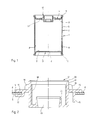
- Figure 1 shows a can-like package 2 in a cylindrical shape. But it can also be oval, non-circular or polygonal.
- the packaging consists of a sleeve 2, a bottom 3 and a sealing membrane 4.
- the bottom 3 and the closure membrane 4 are designed as a deep-drawing line and placed on the end faces of the sleeve 2.
- the sleeve 2 consists of a paper or cardboard composite 5.
- the bottom 3 can have a cardboard composite 6
- the closure membrane 4 can have a cardboard composite 7.
- the wall thickness of the cardboard composite 5 of the sleeve 2, and possibly also the cardboard composite 6 of the base 3, will be greater than that of the cardboard composite 7 of the sealing membrane 4.
- the sleeve 2, the base 3 and the sealing membrane 4, preferably on the inside have a Metal foil or metal coating to ensure a gas and liquid tight execution.
- the sleeve 2, the bottom 3 and the closure membrane 4 are provided with a sealable plastic coating 8.
- the closure membrane 4 also has a similar plastic coating on the outside.
- the bottom 3 and the closure membrane 4 are placed on their edge 9, 10 around the end face of the sleeve 2 and sealed to the sleeve in the entire edge area.
- the closure membrane 4 has a central opening 11 into which a neck part 12 is inserted.
- the neck part 12 serves to receive a closure, a removal device, e.g. a dispenser, atomizer or the like.
- FIG. 2 shows the neck part 12 according to FIG. 1 enlarged, the neck part 12 being shown in the right part of the illustration before being fastened to the closure membrane 4 and in the left part of the illustration after being fastened.
- the neck part 12 has a cylindrical center piece 13 and a collar 14 formed thereon, which lies on the outside of the closure membrane 4. Furthermore, the neck part 12 has a sleeve-like extension 15, which extends through the opening 11 and projects beyond the closure membrane 4 on the inside.
- the Collar can optionally be formed on the central piece 13 radially extending ribs 16.
- the cylindrical extension 15 is molded onto the inside of the closure membrane 4 to form an inner collar 17. This can be done by applying heat or preferably by ultrasound.
- the deformed collar 17 is then sealed in the same technique, that is, preferably by ultrasound, with the plastic coating 8 on the inside of the closure membrane 4.
- the outer collar 14 can also be sealed with the closure membrane 4 by also having a corresponding plastic coating on the outside. In this way, a hermetic seal between the neck part 12 and the closure membrane 4 can be achieved.
- the neck part 12 has an internal thread 18. Furthermore, the middle piece 13 is drawn in at its inner end and provided with a cylindrical projection 19 which in turn projects upwards.
- This embodiment of the neck part 12 is particularly suitable for receiving an atomizer head with a hand pump, by means of which liquid filling material, for example, can be removed from the packaging 1 and atomized via an immersion tube.
- the neck part 12 has on its outer end face a sealing edge 20 against which, for example, a cap of the atomizer seals.
- the neck part 12, for example on the cylindrical extension 19, can have a further sealing surface 21, against which, for example, a round cord seal or the like rests on the atomizer head.
- FIG. 3 shows an embodiment of an atomizer 22 which is placed on a can-like packaging 1.
- the packaging has, as in the exemplary embodiment according to FIG. 1 a sleeve 2, a bottom 3 and a sealing membrane 4.
- the neck part 12 is inserted into the closure membrane 4 and sealed to the closure membrane 4 with its inner collar 17.
- the neck part 12 has essentially radially extending projections 23 on the outside of the closure membrane 4, which are provided with catch-like undercuts 24.
- mutually opposite handles 25 are arranged radially resiliently, which engage undercuts 24 on the neck part 12 with lugs 26.
- the atomizer 22 is put on from above and the lugs 26 snap into the undercuts 24 under slight pressure.
- the atomizer 22 has a cap 27 which seals under the clamping action generated by the lugs 26 on the undercuts 24 by means of a round cord ring 28 against the inner edge of the neck part 12.
- FIG. 4 shows the process steps for producing the connection between neck part 12 and closure membrane 4.
- the closure membrane 4 consists of a cardboard composite 30 and a coating 31, 32 on both sides made of plastic, for example PE.
- the neck part which is also made of plastic, for example PE, by injection molding, has a molded-on shoulder, for example a collar 33 - similar to the collar 14 according to FIG. 2.
- the closure membrane 4 is plugged with its opening 11 onto the neck part 12 from one end face thereof.
- the neck part is placed with its collar 33 on an abutment 34 (Fig. 4b).
- the neck part is then thermally expanded from the front face.
- the sonotrode 35 of an ultrasonic welding device which has a head 36 which partially penetrates into the neck part, is preferably used for this purpose.
- the sonotrode 35 By lowering the sonotrode 35 (FIG. 4c), the upper region of the neck part is displaced further and further and finally against the closure membrane 4 is formed (Fig. 4d).
- the prefabricated collar 33 and the molded collar 37 are sealed with the coating 31, 32 of the closure membrane by ultrasound, and thus a moisture and gas-tight connection of the neck part 12 and the closure membrane 4 is produced.
Abstract
Description
Die Erfindung betrifft eine dosenartige Verpackung für fließfähige Produkte, bestehend aus einer Hülse, einem deren eine Stirnseite abschließenden Boden und einer deren andere Stirnseite abschließenden Verschlußmembran, wobei zunächst die Hülse und der Boden aus einem Papier- oder Kartonverbund gebildet und diese sowie die Verschlußmembran innenseitig mit einer siegelfähigen Kunststoffschicht versehen sind, mittels der sie dicht miteinander verbindbar sind. Ferner ist die Erfindung auf ein Verfahren zur Herstellung der vorgenannten Verpackung gerichtet.The invention relates to a can-like packaging for flowable products, consisting of a sleeve, a bottom closing one end and a closing membrane closing its other end, wherein first the sleeve and the bottom are formed from a paper or cardboard composite and this and the closure membrane inside are provided with a sealable plastic layer, by means of which they can be tightly connected to one another. The invention is also directed to a method for producing the aforementioned packaging.
Verpackungen des vorgenannten Aufbaus werden heute in vielfältiger Weise eingesetzt, z.B. im Nahrungsmittelbereich für Instantpulver, Konfitüren etc. Sie bestehen zum überwiegenden Teil aus Papier- oder Kartonverbundmaterial und sind in der Regel lediglich mit einer Metallfolie oder einem Metallack für die notwendige Flüssigkeits- und Gasdichtheit versehen. Damit sind diese Verpackungen gegenüber reinen Kunststoffverpackungen umweltschonend verwertbar. Auch ist der Energieeinsatz für ihre Herstellung sehr gering, zumal der Papier- bzw. Kartonverbund aus Recyclingprozessen stammen kann. Auch der reine Masseneinsatz ist relativ gering.Packaging of the aforementioned construction is used today in a variety of ways, for example in the food sector for instant powder, jams, etc. They consist predominantly of paper or cardboard composite material and are usually only provided with a metal foil or a metal sack for the necessary liquid and gas tightness . This makes these packaging different from pure plastic packaging usable in an environmentally friendly way. The use of energy for their production is also very low, especially since the paper or cardboard composite can come from recycling processes. The pure mass use is also relatively low.
Für die Entnahme des Füllgutes wird die Verschlußmembran aufgebrochen. Um das nicht entnommene Füllgut zu schützen, muß dann in der Regel ein weiterer Kunststoffdeckel vorgesehen werden, mit dem die geöffnete Verpackung verschlossen werden kann. Hierbei ist von Nachteil, daß eine solcher Deckel in der Regel keinen dichten Abschluß gewährt.The sealing membrane is broken open to remove the filling material. In order to protect the contents that have not been removed, a further plastic cover must then generally be provided, with which the opened packaging can be closed. The disadvantage here is that such a cover usually does not provide a tight seal.
Ein weiterer Nachteil dieser Verpackungen, die auch als Kombidosen bezeichnet werden, besteht darin, daß sie nicht mit Entnahmeeinrichtungen, wie Spender, Zerstäuber oder dergleichen ausgestattet werden können, so daß ein großes Segment an Füllgut und an Anwendungsmöglichkeiten diesen Verpackungen verschlossen bleibt. Es ist schon versucht worden (DE-A-38 42 909) die Vorteile solcher Verbundverpackungen auch für solche Füllgüter zu nutzen, die mittels Spender, Zerstäuber oder dergleichen entnommen werden, indem auch die die Verschlußmembran nach oben überragende Hülse ausreichend elastisch gestaltet ist, daß eine Kappe mit Gewinde unter gleichzeitigem Verformen des Hülsenmaterials aufgeschraubt werden kann und diese Kappe dann eine entsprechende Entnahmeeinrichtung aufweist. In dieser Ausführung wird insbesondere das Ziel verfolgt, die Entnahmeeinrichtung, z.B. eine Zerstäuberpumpe mit Zerstäuberkopf auswechselbar an der Hülse anzubringen und damit wiederverwendbar zu machen, während die Verpackung nach dem Entleeren weggeworfen und die Entnahmeeinrichtung auf eine neue Verpackung, die durch die Verschlußmembran verschlossen ist, nach deren Auftrennen aufgesetzt wird. Hierbei ergeben sich jedoch Schwierigkeiten hinsichtlich einer einwandfreien Verbindung und Abdichtung.Another disadvantage of these packagings, which are also referred to as combination cans, is that they cannot be equipped with removal devices, such as dispensers, atomizers or the like, so that a large segment of filling goods and possible applications remains closed to these packagings. Attempts have already been made (DE-A-38 42 909) to use the advantages of such composite packaging also for those fillings which are removed by means of dispensers, atomizers or the like, in that the sleeve, which projects above the sealing membrane, is designed to be sufficiently elastic that a threaded cap can be screwed on while deforming the sleeve material and this cap then has a corresponding removal device. In this embodiment, the aim is in particular to attach the removal device, for example an atomizing pump with an atomizing head, to the sleeve so that it can be reused, while the packaging is thrown away after emptying and the removal device is placed on a new packaging which is closed by the closure membrane. after they have been separated. However, there are difficulties with regard to a perfect connection and sealing.
Der Erfindung liegt die Aufgabe zugrunde, eine Verpackung des eingangs genannten Aufbaus, die also überwiegend aus Papier- oder Kartonverbund besteht, so auszubilden, daß herkömmliche Verschlüsse oder Entnahmeeinrichtungen, wie sie bei Kunststoff-, Glas- oder Metallverpackungen bekannt sind, eingesetzt werden können, insbesondere nach dem Öffnen auch ein erneuter dichter Verschluß möglich ist.The invention is based on the object of designing a packaging of the structure mentioned at the outset, which therefore consists predominantly of paper or cardboard composite, in such a way that conventional closures or removal devices, as are known for plastic, glass or metal packaging, can be used, especially after opening, a tight seal is possible.
Diese Aufgabe wird erfindungsgemäß dadurch gelöst, daß die Verschlußmembran eine Öffnung und an ihrer Außenseite gleichfalls eine siegelfähige Kunststoffschicht aufweist und daß ein Halsteil aus formstabilem Kunststoff vorgesehen ist, das mit einem Kragen der Verschlußmembran außenseitig anliegt und deren Öffnung mit einem hülsenartigen Ansatz durchgreift, und daß der Ansatz zu einem der Membran innenseitig anliegenden Kragen umgeformt ist und wenigstens einer der beiden Kragen mit der Kunststoffschicht der Verschlußmembran verschweißt ist.This object is achieved in that the closure membrane has an opening and on the outside also has a sealable plastic layer and that a neck part made of dimensionally stable plastic is provided, which rests on the outside with a collar of the closure membrane and whose opening engages with a sleeve-like approach, and that the approach is formed into a collar lying on the inside of the membrane and at least one of the two collars is welded to the plastic layer of the closure membrane.
Mit der erfindungsgemäßen Ausbildung wird eine überwiegend aus Papier- oder Kartonverbund bestehende Verpackung geschaffen, die aufgrund des eingesetzten Halsteils praktisch jede herkömmliche Möglichkeit für das dichte Verschließen, das Einsetzen von Spendern, Zerstäubern oder dergleichen gestattet. Dabei wird der aus Umweltschutzgründen unerwünschte Kunststoffanteil auf ein Minimum, nämlich das Halsteil, beschränkt. Durch das Versiegeln des Halsteils mittel eines seiner Kragen mit der Verschlußmembran ergibt sich eine gas- und flüssigkeitsdichte Verbindung zwischen Halsteil und Verschlußmembran. Das Halsteil selbst wiederum bietet die Möglichkeit der dichten Anbringung von Schraub-, Steck-, Rastverschlüssen oder dergleichen. Dabei kann es sich ausschließlich um Verschlüsse handeln oder aber auch um Verschlußteile von Spendern, Zerstäubern oder dergleichen, die wiederverwendbar auf Nachfüllpackungen gleichen Aufbaus aufgesetzt werden können.With the design according to the invention, a packaging consisting predominantly of paper or cardboard is created which, owing to the neck part used, allows practically every conventional option for tight sealing, the use of dispensers, atomizers or the like. The plastic component, which is undesirable for environmental reasons, is limited to a minimum, namely the neck part. Sealing the neck part by means of one of its collars with the closure membrane results in a gas and liquid-tight connection between the neck part and the closure membrane. The neck part itself offers the possibility of tight attachment of screw, plug, snap closures or the like. These can only be closures or also closure parts from dispensers, atomizers or the like, which can be reusably placed on refill packs of the same construction.
In bevorzugter Ausführungsform ist vorgesehen, daß beide Kragen mit den Kunststoffschichten der Verschlußmembran versiegelt sind, wodurch eine erhöhte Dichtzeit gewährleistet ist. Diese Ausführung eignet sich vor allem auch bei großvolumigeren Verpackungen mit entsprechend großflächiger Verschlußmembran, da diese im mittleren Bereich durch das Halsteil ausgesteift wird. Auch ist die Erfindung bei beliebigen Verpackungsquerschnitten (rund, unrund, mehreckig oder dergleichen) anwendbar.In a preferred embodiment it is provided that both collars are sealed with the plastic layers of the closure membrane, which ensures an increased sealing time. This version is particularly suitable for large-volume packaging with a correspondingly large sealing membrane, since this is stiffened in the middle by the neck part. The invention is also applicable to any packaging cross-section (round, non-circular, polygonal or the like).
Vorzugsweise ist der Ansatz des Halsteils mittels Ultraschall zu dem Kragen umgeformt, wobei auch das Verschweißen der Kragen mit den Kunststoffschichten der Verschlußmembran durch Ultraschall erfolgen kann. Es ist also insbesondere möglich, sowohl das Umformen, als auch das Versiegeln in einem einzigen Arbeitsgang und in einem Werkzeug vorzunehmen.The neck portion is preferably formed into the collar by means of ultrasound, and the collar can also be welded to the plastic layers of the closure membrane by means of ultrasound. It is therefore particularly possible to carry out both the forming and the sealing in a single operation and in one tool.
Die Erfindung eröffnet ferner die Möglichkeit, auch die Verschlußmembran aus einem Papier- oder Kartonverbund herzustellen, so daß der Anteil umweltfreundlicher und energiesparender Werkstoffe weitervergrößert wird.The invention also opens up the possibility of also producing the closure membrane from a paper or cardboard composite, so that the proportion of environmentally friendly and energy-saving materials is further increased.
Wie bereits angedeutet, kann das Halsteil ein Außen- oder Innengewinde oder aber ein Rast- oder Steckprofil für einen Verschluß, eine Entnahmeeinrichtung oder dergleichen aufweisen. Ferner kann sie in einer bei Kunststoffverhältnissen üblichen Weise Dichtflächen oder umlaufende Dichtkanten aufweisen, um einen dichten Abschluß für das Füllgut bzw. eine begrenzt druckfeste Ausbildung zu erreichen.As already indicated, the neck part can have an external or internal thread or else a latching or plug-in profile for a closure, a removal device or the like. Furthermore, it can have sealing surfaces or circumferential sealing edges in a manner customary in the case of plastics, in order to achieve a tight seal for the filling material or a limited pressure-resistant design.
In weiterhin vorteilhafter Ausgestaltung ist vorgesehen, daß die außenliegende Stirnseite des Halsteils in oder unterhalb der Ebene der Stirnseite der Hülse liegt, diese Stirnseite also nicht überragt. Damit ergibt ergibt sich eine gute axiale Druckfestigkeit des Behälters, insbesondere wenn er als Nachfüllbehälter ausgebildet ist, indem evtl. axiale Druckkräfte von der Stirnseite der Hülse aufgenommen werden und nicht auf die Membran selbst einwirken können.In a further advantageous embodiment it is provided that the outer end face of the neck part lies in or below the plane of the end face of the sleeve, so that this end face does not protrude. This results in a good axial compressive strength of the container, especially if it is designed as a refill container, possibly by axial compressive forces be taken up from the front of the sleeve and can not act on the membrane itself.
Eine weiterhin bevorzugte Ausführungsform zeichnet sich dadurch aus, daß das mit Innengewinde versehene Halsteil einen gegenüber dem Innendurchmesser der Öffnung der Verschlußmembran kleineren Außendurchmesser aufweist und bis in den Behälter hineinragt und daß der der Verschlußmembran außenseitig anliegende Kragen den hülsenförmigen Ansatz aufweist, der die Öffnung durchgreift und zu dem inneren Kragen umgeformt ist.A further preferred embodiment is characterized in that the internally threaded neck part has an outer diameter which is smaller than the inner diameter of the opening of the closure membrane and projects into the container and that the collar which lies on the outside of the closure membrane has the sleeve-shaped projection which passes through the opening and is formed into the inner collar.
Diese Ausführung gestattet es, das Innengewinde bis in das Innere des Behälters hineinzuziehen, den außenliegenden Bereich des Halsteils also sehr kurz zu gestalten und trotzdem noch die notwendige Tragfähigkeit am Gewinde zu erhalten. Eine solche Ausführung läßt sich bei herkömmlichen Kunststoffverpackungen, die im Blasverfahren hergestellt werden, überhaupt nicht erreichen.This design allows the internal thread to be drawn into the interior of the container, making the outer area of the neck part very short and still maintaining the necessary load-bearing capacity on the thread. Such an embodiment cannot be achieved at all with conventional plastic packaging which is produced by the blowing process.
In weiterhin vorteilhafter Ausführung ist vorgesehen, daß das Halsteil wenigstens zwei auf der Verschlußmembran aufliegende, im wesentlichen radial verlaufende Ansätze aufweist, die mit rastenartigen Hinterschnitten versehen sind, und daß der Verschluß bzw. die Entnahmeeinrichtung mit die Rasten federnd hintergreifenden Nasen versehen ist.In a further advantageous embodiment it is provided that the neck part has at least two substantially radially extending lugs resting on the closure membrane, which are provided with catch-like undercuts, and that the closure or the removal device is provided with resiliently engaging lugs.
Die vorgenannte Ausführungsform gibt die Möglichkeit, einen Spender, Zerstäuber oder dergleichen durch einen einfachen Rastvorgang auf das Halsteil aufzusetzen. Dabei kann das Verrasten mit einer solchen Vorspannung erfolgen, daß eine einwandfreie Abdichtung auf dem Halsteil möglich ist.The aforementioned embodiment gives the possibility of placing a dispenser, atomizer or the like on the neck part by a simple latching process. The locking can be done with such a pretension that a perfect seal on the neck part is possible.
Wie bereits angedeutet, kann das Halsteil an seiner Öffnung mit einer Membran versiegelt sein. In dieser Ausführung kann die Verpackung als Nachfüllpackung für eine mit der Erstpackung vom Kunden gekauften Spender, Zerstäuber oder dergleichen eingesetzt werden.As already indicated, the neck part can be sealed with a membrane at its opening. In this embodiment, the packaging can be used as a refill for a dispenser, atomizer or the like bought by the customer with the first packaging.
Ein besonders einfaches und kostengünstiges Verfahren zur Herstellung der erfindungsgemäßen Verpackung geht von einem aus der DE-A-28 46 755 bekannten Stand der Technik aus und zeichnet sich durch die in den Patentansprüchen 13 bis 16 gekennzeichneten Merkmale aus. Die nachdem erfindungsgemäßen Verfahren mit dem Halsteil versehene Verschlußmembran wird anschließend in herkömmlicher Weise mit der Hülse verbunden.A particularly simple and inexpensive method for producing the packaging according to the invention is based on the prior art known from DE-A-28 46 755 and is characterized by the features characterized in
Nachstehend ist die Erfindung anhand von in der Zeichnung wiedergegebenen Ausführungsbeispielen beschrieben. In der Zeichnung zeigen:
Figur 1- einen Axialschnitt einer ersten Ausführungsform der Erfindung;
Figur 2- eine vergrößerte Ansicht des Halsteils gemäß
Figur 1; Figur 3- eine Ausführungsform einer Verpackung mit einem Zerstäuber, teilweise im Axialschnitt, und
- Figur 4a) bis d)
- eine schematische Ansicht verschiedener Stufen bei der Verbindung von Halsteil und Verschlußmembran.
- Figure 1
- an axial section of a first embodiment of the invention;
- Figure 2
- an enlarged view of the neck portion of Figure 1;
- Figure 3
- an embodiment of a package with an atomizer, partially in axial section, and
- 4a) to d)
- is a schematic view of various stages in the connection of the neck part and closure membrane.
Figur 1 zeigt ein dosenartige Verpackung 2 in zylindrischer Form. Sie kann aber ebensogut oval, unrund oder mehreckig ausgebildet sein. Die Verpackung besteht aus einer Hülse 2, einem Boden 3 und einer Verschlußmembran 4. Der Boden 3 und die Verschlußmembran 4 sind als Tiefziehzeile ausgebildet und auf die Stirnseiten der Hülse 2 aufgesetzt.Figure 1 shows a can-
Die Hülse 2 besteht aus einem Papier- oder Kartonverbund 5. Ebenso können der Boden 3 einen Kartonverbund 6 und die Verschlußmembran 4 einen Kartonverbund 7 aufweisen. Dabei wird die Wandstärke des Kartonverbundes 5 der Hülse 2, wie auch möglicherweise der Kartonverbund 6 des Bodens 3 größer sein als beim Kartonverbund 7 der Verschlußmembran 4. Ferner weisen die Hülse 2, der Boden 3 und die Verschlußmembran 4, vorzugsweise an der Innenseite, eine Metallfolie oder Metallackierung auf, um eine gas- und flüssigkeitsdichte Ausführung zu gewährleisten. An der Innenseite sind die Hülse 2, der Boden 3 und die Verschlußmembran 4 mit einer siegelfähigen Kunststoffbeschichtung 8 versehen. Darüber hinaus weist die Verschlußmembran 4 auch an der Außenseite eine gleichartige Kunststoffbeschichtung auf.The
Der Boden 3 und die Verschlußmembran 4 sind an ihrem Rand 9, 10 um die Stirnseite der Hülse 2 herumgelegt und im gesamten Randbereich an die Hülse angesiegelt.The
Die Verschlußmembran 4 weist eine mittige Öffnung 11 auf, in die ein Halsteil 12 eingesetzt ist. Das Halsteil 12 dient zur Aufnahme eines Verschlusses, einer Entnahmeeinrichtung, z.B. eines Spenders, Zerstäubers oder dergleichen.The
In Figur 2 ist das Halsteil 12 gemäß Figur 1 vergrößert dargestellt, wobei im rechten Teil der Darstellung das Halsteil 12 vor dem Befestigen an der Verschlußmembran 4, im linken Teil der Darstellung nach dem Befestigen gezeigt ist. Das Halsteil 12 weist ein zylindrisches Mittelstück 13 und einen daran angeformten Kragen 14 auf, der der Verschlußmembran 4 außenseitig aufliegt. Ferner besitzt das Halsteil 12 einen hülsenartigen Ansatz 15, der die Öffnung 11 durchgreift und die Verschlußmembran 4 innenseitig überragt. Zur Aussteifung des Kragens können am Mittelstück 13 gegebenenfalls noch radial verlaufende Rippen 16 angeformt sein.FIG. 2 shows the
Nach dem Einsetzen des Halsteils 12 bzw. des hülsenartigen Ansatzes 15 in die Öffnung 11 der Verschlußmembran 4 wird der zylindrische Ansatz 15 an die Innenseite der Verschlußmembran 4 unter Bildung eines inneren Kragens 17 angeformt. Dies kann durch Wärmezufuhr oder vorzugsweise durch Ultraschall geschehen. Der umgeformte Kragen 17 wird dann in der gleichen Technik, also vorzugsweise durch Ultraschall, mit der innenseitigen Kunststoffbeschichtung 8 der Verschlußmembran 4 versiegelt. In gleicher Weise kann auch der äußere Kragen 14 mit der Verschlußmembran 4 versiegelt werden, indem diese auch außenseitig eine entsprechende Kunststoffbeschichtung aufweist. Auf diese Weise läßt sich ein hermetischer Abschluß zwischen Halsteil 12 und Verschlußmembran 4 erzielen.After inserting the
Beim gezeigten Ausführungsbeispiel weist das Halsteil 12 ein Innengewinde 18 auf. Ferner ist das Mittelstück 13 an seinem innenliegenden Ende nach innen eingezogen und mit einem wiederum nach oben ragenden zylindrischen Ansatz 19 versehen. Diese Ausführungsform des Halsteils 12 eignet sich insbesondere zur Aufnahme eines Zerstäuberkopfs mit Handpumpe, mittels der über ein Tauchrohr beispielsweise flüssiges Füllgut aus der Verpackung 1 entnommen und zerstäubt werden kann. Für diesen Zweck weist das Halsteil 12 an seiner außenliegenden Stirnseite eine Dichtkante 20 auf, gegen die beispielsweise eine Kappe des Zerstäubers abdichtet. Gegebenenfalls kann das Halsteil 12, beispielsweise an den zylindrischen Ansatz 19 eine weitere Dichtfläche 21 aufweisen, gegen die beispielsweise eine Rundschnurdichtung oder dergleichen am Zerstäuberkopf anliegt.In the exemplary embodiment shown, the
In Figur 3 ist eine Ausführungsform eines Zerstäubers 22 gezeigt, der auf eine dosenartige Verpackung 1 aufgesetzt ist. Die Verpackung weist, wie beim Ausführungsbeispiel nach Figur 1 eine Hülse 2, einen Boden 3 und eine Verschlußmembran 4 auf. In die Verschlußmembran 4 ist das Halsteil 12 eingesetzt und mit seinem innenliegenden Kragen 17 an die Verschlußmembran 4 angesiegelt.FIG. 3 shows an embodiment of an
Bei diesem Ausführungsbeispiel weist das Halsteil 12 im wesentlichen radial verlaufende Ansätze 23 an der Außenseite der Verschlußmembran 4 auf, die mit rastartigen Hinterschnitten 24 versehen sind. An dem Zerstäuber 22 sind einander gegenüberliegende Handhaben 25 radial federnd angeordnet, die mit Nasen 26 die Hinterschnitte 24 am Halsteil 12 untergreifen. Der Zerstäuber 22 wird von oben aufgesetzt und unter leichtem Druck schnappen die Nasen 26 in die Hinterschnitte 24 ein. Zur zusätzlichen Abdichtung weist der Zerstäuber 22 eine Kappe 27 auf, die unter der von den Nasen 26 an den Hinterschnitten 24 erzeugten Klemmwirkung mittels eines Rundschnurrings 28 gegen den Innenrand des Halsteils 12 abdichtet.In this exemplary embodiment, the
In Figur 4 sind die Verfahrensschritte zur Herstellung der Verbindung von Halsteil 12 und Verschlußmembran 4 wiedergegeben. Die Verschlußmembran 4 besteht, wie schon angedeutet, aus einem Kartonverbund 30 und einer beidseitigen Beschichtung 31, 32 aus Kunststoff, z.B. PE. Das Halsteil, das gleichfalls aus Kunststoff, z.B. PE, im Wege des Spritzgießens hergestellt, weist einen angeformten Absatz, z.B. einen Bund 33 - ähnlich dem Kragen 14 gemäß Fig 2 - auf. Die Verschlußmembran 4 wird mit ihrer Öffnung 11 auf das Halsteil 12 von dessen einer Stirnseite her aufgesteckt. Zu diesem Zweck wird das Halsteil mit seinem Bund 33 auf ein Widerlager 34 aufgelegt (Fig. 4b). Anschließend wird das Halsteil von der Aufsteck-Stirnseite her thermisch aufgeweitet. Hierzu dient vorzugsweise die Sonotrode 35 einer Ultraschallschweißeinrichtung, die einen in das Halsteil teilweise eindringenden Kopf 36 aufweist. Durch Absenken der Sonotrode 35 (Fig. 4c) wird der obere Bereich des Halsteils immer weiter nach außen verdrängt und schließlich gegen die Verschlußmembran 4 angeformt (Fig. 4d). In der Endlage werden der vorgefertigte Bund 33 und der angeformte Bund 37 mit der Beschichtung 31, 32 der Verschlußmembran durch Ultraschall versiegelt und somit eine feuchtigkeits- und gasdichte Verbindung von Halsteil 12 und Verschlußmembran 4 hergestellt.FIG. 4 shows the process steps for producing the connection between
Claims (16)
Applications Claiming Priority (2)
| Application Number | Priority Date | Filing Date | Title |
|---|---|---|---|
| DE4009397A DE4009397A1 (en) | 1990-03-23 | 1990-03-23 | CAN-LIKE PACKAGING FOR FLOWABLE PRODUCTS |
| DE4009397 | 1990-03-23 |
Publications (2)
| Publication Number | Publication Date |
|---|---|
| EP0447997A2 true EP0447997A2 (en) | 1991-09-25 |
| EP0447997A3 EP0447997A3 (en) | 1993-02-03 |
Family
ID=6402927
Family Applications (1)
| Application Number | Title | Priority Date | Filing Date |
|---|---|---|---|
| EP19910104085 Withdrawn EP0447997A3 (en) | 1990-03-23 | 1991-03-16 | Can-like package for flowable products and method for its manufacture |
Country Status (2)
| Country | Link |
|---|---|
| EP (1) | EP0447997A3 (en) |
| DE (1) | DE4009397A1 (en) |
Cited By (2)
| Publication number | Priority date | Publication date | Assignee | Title |
|---|---|---|---|---|
| EP0546898A1 (en) * | 1991-12-13 | 1993-06-16 | Conceptair B.V. | Rechargeable device for spraying a fluid |
| IT202000027618A1 (en) * | 2020-11-18 | 2022-05-18 | Lumson Spa | FLUID SUBSTANCE DELIVERY DEVICE |
Families Citing this family (6)
| Publication number | Priority date | Publication date | Assignee | Title |
|---|---|---|---|---|
| DE19502992A1 (en) * | 1995-02-01 | 1996-08-08 | Brain Power Consulting Gmbh | Process for producing hollow bodies and hollow bodies according to this method |
| CA2218179A1 (en) | 1995-04-14 | 1996-10-17 | Glaxo Wellcome Inc. | Metered dose inhaler for beclomethasone dipropionate |
| EP1769819A3 (en) | 1995-04-14 | 2013-05-22 | GlaxoSmithKline LLC | Metered dose inhaler for fluticasone propionate |
| CA2217950C (en) * | 1995-04-14 | 2001-12-25 | Glaxo Wellcome Inc. | Metered dose inhaler for albuterol |
| AP979A (en) | 1995-04-14 | 2001-06-28 | Glaxo Wellcome Inc | Metered dose imhaler for salmeterol. |
| US8227027B2 (en) | 2007-12-07 | 2012-07-24 | Presspart Gmbh & Co. Kg | Method for applying a polymer coating to an internal surface of a container |
Citations (3)
| Publication number | Priority date | Publication date | Assignee | Title |
|---|---|---|---|---|
| US2215268A (en) * | 1938-07-07 | 1940-09-17 | Himmer Vitalis | Container |
| DE3526682A1 (en) * | 1985-07-25 | 1987-01-29 | Noefa Gmbh | Opening part for a container, method for producing a container and device for carrying out the method |
| DE3842909A1 (en) * | 1987-12-24 | 1989-07-06 | Weidenhammer Packungen | Package for delivering free-flowing products |
Family Cites Families (12)
| Publication number | Priority date | Publication date | Assignee | Title |
|---|---|---|---|---|
| US2522772A (en) * | 1947-03-18 | 1950-09-19 | Cordelia P Benjamin | Container |
| DE1810211U (en) * | 1960-01-26 | 1960-04-21 | F W Oventrop Arn Sohn K G | PUMP FIXED IN THE FILLING SOCKET OF A DRUM. |
| US3072312A (en) * | 1961-02-10 | 1963-01-08 | Cleveland Container Corp | Fluid container |
| GB1417397A (en) * | 1972-02-17 | 1975-12-10 | Hoechst Uk Ltd | Adapters for containers |
| IT1097763B (en) * | 1978-07-28 | 1985-08-31 | Cartotecnica Poligrafica A & G | DRUM OR SIMILAR CONTAINER, ESPECIALLY INTENDED TO CONTAIN FOLVERULENT MATERIAL, SUCH AS CD DETERGENTS OTHER |
| DE2849755A1 (en) * | 1978-11-16 | 1980-05-29 | Eckes Fa Peter | DEVICE FOR REPEATING OPENING AND CLOSING AN OPENING IN A LID OF A CONTAINER |
| NZ200030A (en) * | 1981-03-30 | 1985-07-12 | Waddington & Duval Ltd | Dispensing valve breaks seal on first depression |
| EP0318465B1 (en) * | 1985-03-14 | 1992-01-02 | MegaPlast Dosiersysteme GmbH & Co. | Metering pump with pumping bellows for bottles or same |
| GB2187712B (en) * | 1986-03-11 | 1990-05-23 | Tetra Pak Finance & Trading | Fluid pack and process for the production therof |
| DE3832412C2 (en) * | 1987-09-24 | 2002-10-02 | Dainippon Printing Co Ltd | Liquid-tight cardboard container with a liquid pouring device |
| DE8814473U1 (en) * | 1988-11-19 | 1989-03-30 | Sieger Plastic Gmbh, 5160 Dueren, De | |
| DE8907247U1 (en) * | 1989-06-14 | 1989-08-24 | Bauer, Heinz-Dieter, 4286 Suedlohn, De |
-
1990
- 1990-03-23 DE DE4009397A patent/DE4009397A1/en not_active Withdrawn
-
1991
- 1991-03-16 EP EP19910104085 patent/EP0447997A3/en not_active Withdrawn
Patent Citations (3)
| Publication number | Priority date | Publication date | Assignee | Title |
|---|---|---|---|---|
| US2215268A (en) * | 1938-07-07 | 1940-09-17 | Himmer Vitalis | Container |
| DE3526682A1 (en) * | 1985-07-25 | 1987-01-29 | Noefa Gmbh | Opening part for a container, method for producing a container and device for carrying out the method |
| DE3842909A1 (en) * | 1987-12-24 | 1989-07-06 | Weidenhammer Packungen | Package for delivering free-flowing products |
Cited By (6)
| Publication number | Priority date | Publication date | Assignee | Title |
|---|---|---|---|---|
| EP0546898A1 (en) * | 1991-12-13 | 1993-06-16 | Conceptair B.V. | Rechargeable device for spraying a fluid |
| FR2684901A1 (en) * | 1991-12-13 | 1993-06-18 | Conceptair Anstalt | METHOD AND DEVICE FOR PREVENTING THE FORMATION OF GAS POCKETS IN A RESERVOIR FOR A FLUID PRODUCT INTENDED TO BE PULVERIZED OR DISPENSED WITHOUT RETURNING AIR. |
| US5417258A (en) * | 1991-12-13 | 1995-05-23 | Conceptair Anstalt | Rechargeable device for spraying a fluid |
| IT202000027618A1 (en) * | 2020-11-18 | 2022-05-18 | Lumson Spa | FLUID SUBSTANCE DELIVERY DEVICE |
| EP4000746A1 (en) * | 2020-11-18 | 2022-05-25 | Lumson S.p.A. | A fluid substance dispensing device |
| US11759809B2 (en) | 2020-11-18 | 2023-09-19 | Lumson S.P.A. | Fluid substance dispensing device |
Also Published As
| Publication number | Publication date |
|---|---|
| DE4009397A1 (en) | 1991-09-26 |
| EP0447997A3 (en) | 1993-02-03 |
Similar Documents
| Publication | Publication Date | Title |
|---|---|---|
| EP0182094B1 (en) | Method for making a container with a sealable opening, and container obtained thereby | |
| EP3140213B1 (en) | Mixing/closure device for a container | |
| EP0101594B1 (en) | Two-component package | |
| EP0114398B1 (en) | Compressible laminated tubular container | |
| EP2181051B1 (en) | Dispensing device | |
| DE3017042A1 (en) | METAL CAN WITH MEMBRANE LOCK | |
| EP0675051B1 (en) | Threaded cap with a welded ring | |
| DE102007051980A1 (en) | dispenser | |
| DE2853958A1 (en) | CONTAINER CLOSURE AND PROCESS FOR ITS MANUFACTURING | |
| DE2262989A1 (en) | TUBULAR CONTAINER AND METHOD FOR MANUFACTURING IT | |
| EP1027268B1 (en) | Method for producing a two chamber pressure pack and a device for carrying out the same | |
| EP0447997A2 (en) | Can-like package for flowable products and method for its manufacture | |
| CH635792A5 (en) | Squeezable delivery container | |
| DE60106613T2 (en) | TUBE WITH LARGE NECK DIAMETER AND RIGID ADAPTER | |
| DE2724519C2 (en) | Two-component packaging | |
| EP0079548A2 (en) | Container closure | |
| DE4023274A1 (en) | Double container made of thermoplastics - has spout welded to outer container with collar to protect inner container | |
| EP0659654B1 (en) | Box-like package | |
| EP0731036B1 (en) | Lid | |
| DE6903799U (en) | PACKAGING CAN, IN PARTICULAR FOR GAS-BASED LIQUIDS | |
| DE102005004759A1 (en) | Resealable can and method of making same | |
| EP3589556B1 (en) | Container packaging and method for its manufacturing | |
| EP0322709A2 (en) | Package for dispensing fluid products | |
| DE2253620A1 (en) | COMPRESSIBLE CONTAINER | |
| DE19621617C2 (en) | Method of manufacturing a screw cap |
Legal Events
| Date | Code | Title | Description |
|---|---|---|---|
| PUAI | Public reference made under article 153(3) epc to a published international application that has entered the european phase |
Free format text: ORIGINAL CODE: 0009012 |
|
| AK | Designated contracting states |
Kind code of ref document: A2 Designated state(s): CH DE FR GB IT LI |
|
| PUAL | Search report despatched |
Free format text: ORIGINAL CODE: 0009013 |
|
| AK | Designated contracting states |
Kind code of ref document: A3 Designated state(s): CH DE FR GB IT LI |
|
| 17P | Request for examination filed |
Effective date: 19930716 |
|
| 17Q | First examination report despatched |
Effective date: 19940930 |
|
| STAA | Information on the status of an ep patent application or granted ep patent |
Free format text: STATUS: THE APPLICATION IS DEEMED TO BE WITHDRAWN |
|
| 18D | Application deemed to be withdrawn |
Effective date: 19950213 |