EP0524514A1 - Multi-layered tubular shaped packaging container and method and apparatus for the manufacturing of such a container - Google Patents
Multi-layered tubular shaped packaging container and method and apparatus for the manufacturing of such a container Download PDFInfo
- Publication number
- EP0524514A1 EP0524514A1 EP19920111864 EP92111864A EP0524514A1 EP 0524514 A1 EP0524514 A1 EP 0524514A1 EP 19920111864 EP19920111864 EP 19920111864 EP 92111864 A EP92111864 A EP 92111864A EP 0524514 A1 EP0524514 A1 EP 0524514A1
- Authority
- EP
- European Patent Office
- Prior art keywords
- sleeve
- inner sleeve
- packaging container
- container according
- outer sleeve
- Prior art date
- Legal status (The legal status is an assumption and is not a legal conclusion. Google has not performed a legal analysis and makes no representation as to the accuracy of the status listed.)
- Withdrawn
Links
Images


Classifications
-
- B—PERFORMING OPERATIONS; TRANSPORTING
- B31—MAKING ARTICLES OF PAPER, CARDBOARD OR MATERIAL WORKED IN A MANNER ANALOGOUS TO PAPER; WORKING PAPER, CARDBOARD OR MATERIAL WORKED IN A MANNER ANALOGOUS TO PAPER
- B31C—MAKING WOUND ARTICLES, e.g. WOUND TUBES, OF PAPER, CARDBOARD OR MATERIAL WORKED IN A MANNER ANALOGOUS TO PAPER
- B31C3/00—Making tubes or pipes by feeding obliquely to the winding mandrel centre line
- B31C3/02—Making tubes or pipes by feeding obliquely to the winding mandrel centre line and inserting into a tube end a bottom to form a container
-
- B—PERFORMING OPERATIONS; TRANSPORTING
- B29—WORKING OF PLASTICS; WORKING OF SUBSTANCES IN A PLASTIC STATE IN GENERAL
- B29C—SHAPING OR JOINING OF PLASTICS; SHAPING OF MATERIAL IN A PLASTIC STATE, NOT OTHERWISE PROVIDED FOR; AFTER-TREATMENT OF THE SHAPED PRODUCTS, e.g. REPAIRING
- B29C65/00—Joining or sealing of preformed parts, e.g. welding of plastics materials; Apparatus therefor
- B29C65/02—Joining or sealing of preformed parts, e.g. welding of plastics materials; Apparatus therefor by heating, with or without pressure
- B29C65/18—Joining or sealing of preformed parts, e.g. welding of plastics materials; Apparatus therefor by heating, with or without pressure using heated tools
-
- B—PERFORMING OPERATIONS; TRANSPORTING
- B29—WORKING OF PLASTICS; WORKING OF SUBSTANCES IN A PLASTIC STATE IN GENERAL
- B29C—SHAPING OR JOINING OF PLASTICS; SHAPING OF MATERIAL IN A PLASTIC STATE, NOT OTHERWISE PROVIDED FOR; AFTER-TREATMENT OF THE SHAPED PRODUCTS, e.g. REPAIRING
- B29C66/00—General aspects of processes or apparatus for joining preformed parts
- B29C66/50—General aspects of joining tubular articles; General aspects of joining long products, i.e. bars or profiled elements; General aspects of joining single elements to tubular articles, hollow articles or bars; General aspects of joining several hollow-preforms to form hollow or tubular articles
- B29C66/51—Joining tubular articles, profiled elements or bars; Joining single elements to tubular articles, hollow articles or bars; Joining several hollow-preforms to form hollow or tubular articles
- B29C66/54—Joining several hollow-preforms, e.g. half-shells, to form hollow articles, e.g. for making balls, containers; Joining several hollow-preforms, e.g. half-cylinders, to form tubular articles
- B29C66/542—Joining several hollow-preforms, e.g. half-shells, to form hollow articles, e.g. for making balls, containers; Joining several hollow-preforms, e.g. half-cylinders, to form tubular articles joining hollow covers or hollow bottoms to open ends of container bodies
-
- B—PERFORMING OPERATIONS; TRANSPORTING
- B29—WORKING OF PLASTICS; WORKING OF SUBSTANCES IN A PLASTIC STATE IN GENERAL
- B29C—SHAPING OR JOINING OF PLASTICS; SHAPING OF MATERIAL IN A PLASTIC STATE, NOT OTHERWISE PROVIDED FOR; AFTER-TREATMENT OF THE SHAPED PRODUCTS, e.g. REPAIRING
- B29C66/00—General aspects of processes or apparatus for joining preformed parts
- B29C66/50—General aspects of joining tubular articles; General aspects of joining long products, i.e. bars or profiled elements; General aspects of joining single elements to tubular articles, hollow articles or bars; General aspects of joining several hollow-preforms to form hollow or tubular articles
- B29C66/51—Joining tubular articles, profiled elements or bars; Joining single elements to tubular articles, hollow articles or bars; Joining several hollow-preforms to form hollow or tubular articles
- B29C66/54—Joining several hollow-preforms, e.g. half-shells, to form hollow articles, e.g. for making balls, containers; Joining several hollow-preforms, e.g. half-cylinders, to form tubular articles
- B29C66/545—Joining several hollow-preforms, e.g. half-shells, to form hollow articles, e.g. for making balls, containers; Joining several hollow-preforms, e.g. half-cylinders, to form tubular articles one hollow-preform being placed inside the other
-
- B—PERFORMING OPERATIONS; TRANSPORTING
- B29—WORKING OF PLASTICS; WORKING OF SUBSTANCES IN A PLASTIC STATE IN GENERAL
- B29C—SHAPING OR JOINING OF PLASTICS; SHAPING OF MATERIAL IN A PLASTIC STATE, NOT OTHERWISE PROVIDED FOR; AFTER-TREATMENT OF THE SHAPED PRODUCTS, e.g. REPAIRING
- B29C66/00—General aspects of processes or apparatus for joining preformed parts
- B29C66/70—General aspects of processes or apparatus for joining preformed parts characterised by the composition, physical properties or the structure of the material of the parts to be joined; Joining with non-plastics material
- B29C66/72—General aspects of processes or apparatus for joining preformed parts characterised by the composition, physical properties or the structure of the material of the parts to be joined; Joining with non-plastics material characterised by the structure of the material of the parts to be joined
- B29C66/723—General aspects of processes or apparatus for joining preformed parts characterised by the composition, physical properties or the structure of the material of the parts to be joined; Joining with non-plastics material characterised by the structure of the material of the parts to be joined being multi-layered
- B29C66/7232—General aspects of processes or apparatus for joining preformed parts characterised by the composition, physical properties or the structure of the material of the parts to be joined; Joining with non-plastics material characterised by the structure of the material of the parts to be joined being multi-layered comprising a non-plastics layer
- B29C66/72321—General aspects of processes or apparatus for joining preformed parts characterised by the composition, physical properties or the structure of the material of the parts to be joined; Joining with non-plastics material characterised by the structure of the material of the parts to be joined being multi-layered comprising a non-plastics layer consisting of metals or their alloys
-
- B—PERFORMING OPERATIONS; TRANSPORTING
- B29—WORKING OF PLASTICS; WORKING OF SUBSTANCES IN A PLASTIC STATE IN GENERAL
- B29C—SHAPING OR JOINING OF PLASTICS; SHAPING OF MATERIAL IN A PLASTIC STATE, NOT OTHERWISE PROVIDED FOR; AFTER-TREATMENT OF THE SHAPED PRODUCTS, e.g. REPAIRING
- B29C66/00—General aspects of processes or apparatus for joining preformed parts
- B29C66/70—General aspects of processes or apparatus for joining preformed parts characterised by the composition, physical properties or the structure of the material of the parts to be joined; Joining with non-plastics material
- B29C66/72—General aspects of processes or apparatus for joining preformed parts characterised by the composition, physical properties or the structure of the material of the parts to be joined; Joining with non-plastics material characterised by the structure of the material of the parts to be joined
- B29C66/723—General aspects of processes or apparatus for joining preformed parts characterised by the composition, physical properties or the structure of the material of the parts to be joined; Joining with non-plastics material characterised by the structure of the material of the parts to be joined being multi-layered
- B29C66/7234—General aspects of processes or apparatus for joining preformed parts characterised by the composition, physical properties or the structure of the material of the parts to be joined; Joining with non-plastics material characterised by the structure of the material of the parts to be joined being multi-layered comprising a barrier layer
- B29C66/72341—General aspects of processes or apparatus for joining preformed parts characterised by the composition, physical properties or the structure of the material of the parts to be joined; Joining with non-plastics material characterised by the structure of the material of the parts to be joined being multi-layered comprising a barrier layer for gases
-
- B—PERFORMING OPERATIONS; TRANSPORTING
- B29—WORKING OF PLASTICS; WORKING OF SUBSTANCES IN A PLASTIC STATE IN GENERAL
- B29C—SHAPING OR JOINING OF PLASTICS; SHAPING OF MATERIAL IN A PLASTIC STATE, NOT OTHERWISE PROVIDED FOR; AFTER-TREATMENT OF THE SHAPED PRODUCTS, e.g. REPAIRING
- B29C66/00—General aspects of processes or apparatus for joining preformed parts
- B29C66/70—General aspects of processes or apparatus for joining preformed parts characterised by the composition, physical properties or the structure of the material of the parts to be joined; Joining with non-plastics material
- B29C66/72—General aspects of processes or apparatus for joining preformed parts characterised by the composition, physical properties or the structure of the material of the parts to be joined; Joining with non-plastics material characterised by the structure of the material of the parts to be joined
- B29C66/723—General aspects of processes or apparatus for joining preformed parts characterised by the composition, physical properties or the structure of the material of the parts to be joined; Joining with non-plastics material characterised by the structure of the material of the parts to be joined being multi-layered
- B29C66/7234—General aspects of processes or apparatus for joining preformed parts characterised by the composition, physical properties or the structure of the material of the parts to be joined; Joining with non-plastics material characterised by the structure of the material of the parts to be joined being multi-layered comprising a barrier layer
- B29C66/72343—General aspects of processes or apparatus for joining preformed parts characterised by the composition, physical properties or the structure of the material of the parts to be joined; Joining with non-plastics material characterised by the structure of the material of the parts to be joined being multi-layered comprising a barrier layer for liquids
-
- B—PERFORMING OPERATIONS; TRANSPORTING
- B29—WORKING OF PLASTICS; WORKING OF SUBSTANCES IN A PLASTIC STATE IN GENERAL
- B29C—SHAPING OR JOINING OF PLASTICS; SHAPING OF MATERIAL IN A PLASTIC STATE, NOT OTHERWISE PROVIDED FOR; AFTER-TREATMENT OF THE SHAPED PRODUCTS, e.g. REPAIRING
- B29C66/00—General aspects of processes or apparatus for joining preformed parts
- B29C66/80—General aspects of machine operations or constructions and parts thereof
- B29C66/81—General aspects of the pressing elements, i.e. the elements applying pressure on the parts to be joined in the area to be joined, e.g. the welding jaws or clamps
- B29C66/816—General aspects of the pressing elements, i.e. the elements applying pressure on the parts to be joined in the area to be joined, e.g. the welding jaws or clamps characterised by the mounting of the pressing elements, e.g. of the welding jaws or clamps
- B29C66/8161—General aspects of the pressing elements, i.e. the elements applying pressure on the parts to be joined in the area to be joined, e.g. the welding jaws or clamps characterised by the mounting of the pressing elements, e.g. of the welding jaws or clamps said pressing elements being supported or backed-up by springs or by resilient material
-
- B—PERFORMING OPERATIONS; TRANSPORTING
- B29—WORKING OF PLASTICS; WORKING OF SUBSTANCES IN A PLASTIC STATE IN GENERAL
- B29C—SHAPING OR JOINING OF PLASTICS; SHAPING OF MATERIAL IN A PLASTIC STATE, NOT OTHERWISE PROVIDED FOR; AFTER-TREATMENT OF THE SHAPED PRODUCTS, e.g. REPAIRING
- B29C66/00—General aspects of processes or apparatus for joining preformed parts
- B29C66/80—General aspects of machine operations or constructions and parts thereof
- B29C66/82—Pressure application arrangements, e.g. transmission or actuating mechanisms for joining tools or clamps
- B29C66/822—Transmission mechanisms
- B29C66/8221—Scissor or lever mechanisms, i.e. involving a pivot point
-
- B—PERFORMING OPERATIONS; TRANSPORTING
- B29—WORKING OF PLASTICS; WORKING OF SUBSTANCES IN A PLASTIC STATE IN GENERAL
- B29C—SHAPING OR JOINING OF PLASTICS; SHAPING OF MATERIAL IN A PLASTIC STATE, NOT OTHERWISE PROVIDED FOR; AFTER-TREATMENT OF THE SHAPED PRODUCTS, e.g. REPAIRING
- B29C66/00—General aspects of processes or apparatus for joining preformed parts
- B29C66/80—General aspects of machine operations or constructions and parts thereof
- B29C66/83—General aspects of machine operations or constructions and parts thereof characterised by the movement of the joining or pressing tools
- B29C66/832—Reciprocating joining or pressing tools
- B29C66/8322—Joining or pressing tools reciprocating along one axis
-
- B—PERFORMING OPERATIONS; TRANSPORTING
- B31—MAKING ARTICLES OF PAPER, CARDBOARD OR MATERIAL WORKED IN A MANNER ANALOGOUS TO PAPER; WORKING PAPER, CARDBOARD OR MATERIAL WORKED IN A MANNER ANALOGOUS TO PAPER
- B31C—MAKING WOUND ARTICLES, e.g. WOUND TUBES, OF PAPER, CARDBOARD OR MATERIAL WORKED IN A MANNER ANALOGOUS TO PAPER
- B31C3/00—Making tubes or pipes by feeding obliquely to the winding mandrel centre line
- B31C3/04—Seam processing
-
- B—PERFORMING OPERATIONS; TRANSPORTING
- B65—CONVEYING; PACKING; STORING; HANDLING THIN OR FILAMENTARY MATERIAL
- B65D—CONTAINERS FOR STORAGE OR TRANSPORT OF ARTICLES OR MATERIALS, e.g. BAGS, BARRELS, BOTTLES, BOXES, CANS, CARTONS, CRATES, DRUMS, JARS, TANKS, HOPPERS, FORWARDING CONTAINERS; ACCESSORIES, CLOSURES, OR FITTINGS THEREFOR; PACKAGING ELEMENTS; PACKAGES
- B65D3/00—Rigid or semi-rigid containers having bodies or peripheral walls of curved or partially-curved cross-section made by winding or bending paper without folding along defined lines
- B65D3/22—Rigid or semi-rigid containers having bodies or peripheral walls of curved or partially-curved cross-section made by winding or bending paper without folding along defined lines with double walls; with walls incorporating air-chambers; with walls made of laminated material
-
- B—PERFORMING OPERATIONS; TRANSPORTING
- B65—CONVEYING; PACKING; STORING; HANDLING THIN OR FILAMENTARY MATERIAL
- B65D—CONTAINERS FOR STORAGE OR TRANSPORT OF ARTICLES OR MATERIALS, e.g. BAGS, BARRELS, BOTTLES, BOXES, CANS, CARTONS, CRATES, DRUMS, JARS, TANKS, HOPPERS, FORWARDING CONTAINERS; ACCESSORIES, CLOSURES, OR FITTINGS THEREFOR; PACKAGING ELEMENTS; PACKAGES
- B65D83/00—Containers or packages with special means for dispensing contents
- B65D83/0005—Containers or packages provided with a piston or with a movable bottom or partition having approximately the same section as the container
-
- B—PERFORMING OPERATIONS; TRANSPORTING
- B29—WORKING OF PLASTICS; WORKING OF SUBSTANCES IN A PLASTIC STATE IN GENERAL
- B29K—INDEXING SCHEME ASSOCIATED WITH SUBCLASSES B29B, B29C OR B29D, RELATING TO MOULDING MATERIALS OR TO MATERIALS FOR MOULDS, REINFORCEMENTS, FILLERS OR PREFORMED PARTS, e.g. INSERTS
- B29K2711/00—Use of natural products or their composites, not provided for in groups B29K2601/00 - B29K2709/00, for preformed parts, e.g. for inserts
- B29K2711/12—Paper, e.g. cardboard
- B29K2711/123—Coated
-
- B—PERFORMING OPERATIONS; TRANSPORTING
- B65—CONVEYING; PACKING; STORING; HANDLING THIN OR FILAMENTARY MATERIAL
- B65D—CONTAINERS FOR STORAGE OR TRANSPORT OF ARTICLES OR MATERIALS, e.g. BAGS, BARRELS, BOTTLES, BOXES, CANS, CARTONS, CRATES, DRUMS, JARS, TANKS, HOPPERS, FORWARDING CONTAINERS; ACCESSORIES, CLOSURES, OR FITTINGS THEREFOR; PACKAGING ELEMENTS; PACKAGES
- B65D2565/00—Wrappers or flexible covers; Packaging materials of special type or form
- B65D2565/38—Packaging materials of special type or form
- B65D2565/381—Details of packaging materials of special type or form
- B65D2565/385—Details of packaging materials of special type or form especially suited for or with means facilitating recycling
-
- Y—GENERAL TAGGING OF NEW TECHNOLOGICAL DEVELOPMENTS; GENERAL TAGGING OF CROSS-SECTIONAL TECHNOLOGIES SPANNING OVER SEVERAL SECTIONS OF THE IPC; TECHNICAL SUBJECTS COVERED BY FORMER USPC CROSS-REFERENCE ART COLLECTIONS [XRACs] AND DIGESTS
- Y02—TECHNOLOGIES OR APPLICATIONS FOR MITIGATION OR ADAPTATION AGAINST CLIMATE CHANGE
- Y02W—CLIMATE CHANGE MITIGATION TECHNOLOGIES RELATED TO WASTEWATER TREATMENT OR WASTE MANAGEMENT
- Y02W30/00—Technologies for solid waste management
- Y02W30/50—Reuse, recycling or recovery technologies
- Y02W30/80—Packaging reuse or recycling, e.g. of multilayer packaging
Definitions
- the invention relates to a sleeve-shaped packaging container made of multilayer material with the features of the preamble of claim 1, a method for producing such a sleeve-shaped packaging container with the features of the preamble of claim 9 and devices for producing such a sleeve-shaped packaging container according to the preambles of claims 14 and 15.
- a typical multi-layer structure consists of a cardboard material that is fully laminated on the inside with a film made of plastic or aluminum or a multilayer material, which can also be laminated on the outside with a thin layer of printed paper, plastic film or the like. Because of the recycling problems of such multilayer materials, packaging containers made of all-plastic are preferred in spite of the recycling problems and costs also known for plastics, because pure cardboard material is unsuitable for the majority of packaging goods - whether in the food sector or in the field of chemical products, especially in a liquid or semi-liquid consistency are.
- the invention has for its object a sleeve-shaped packaging container made of multilayer material to create that is easily recyclable. Another aim is that when the inner sleeve is removed there is no risk of contamination of the remaining outer sleeve.
- the sleeve-shaped packaging containers according to the invention have the advantage, among other things, that they can be easily divided into recyclable individual components by the end user.
- “sleeve-shaped" packaging containers are all packaging containers which consist of a more or less inherently rigid, uniformly along their entire length of at least one inner film-like protective layer and a sleeve (sleeve body) constructed with respect to the protective layer on the outside, which have at least one, are preferably provided with a muzzle closure at both ends and which is only filled as a finished sleeve.
- the protective layer and the base layer are “layers”; the base layer in particular is usually multi-layered. It differs from the - not generic - tubular film packaging (EP-A2-0 151 922), in which an already closed, filled tubular film is inserted into a cardboard tube.
- the sleeve body according to the invention can have a conical shape.
- sleeve bodies with a cylindrical sleeve body that is to say with a constant cross section over their entire length, of a polygonal and / or curved, such as circular outer contour, are particularly advantageous.
- a "film - like protective layer” in the sense of the invention consists of a relatively thin - walled layer, preferably made of a sheet material, made of a material which protects the packaged goods from contact with the support layer and thus - indirectly - also before contact with the outside atmosphere of the packaging container . Conversely - protects, in the broadest sense therefore has a separating or sealing function.
- a "support layer" in the sense of the invention gives the sleeve body of the sleeve-shaped packaging container a certain inherent rigidity against deformation attacks from outside or inside, such as bending, compression, internal overpressure or the like.
- the outer sleeve according to the invention and the inner sleeve according to the invention can be displaced relative to one another by pressing or pulling and can thus be separated into two whole parts; a tool according to claim 16, which can also be used for emptying the container, or an elongated object, such as a hammer handle, can serve for this purpose.
- the empty sleeve body is preferably squeezed or tumbled on the side beforehand, the inner sleeve lifting off from the outer sleeve over a large area.
- the outer sleeve or the inner sleeve or both are destroyed during the separation process and are therefore no longer present in the form of a sleeve.
- the separation (pulling apart) of the material of the outer sleeve from the material of the inner sleeve is made possible by a handle on the inner sleeve, which can be handled independently of the outer sleeve, without the inner sleeve beforehand in a region in which it is enclosed by the outer sleeve To have to loosen the outer sleeve.
- a handle on the inner sleeve can consist, for example, in a surface piece of the material of the inner sleeve pointing away from the outer sleeve.
- a muzzle closure which accordingly serves as a handle and is fixedly connected solely to the inner sleeve and therefore not or easily detachably connected to the outer sleeve is not only particularly ergonomic , but allows the problem-free transfer of considerable forces, such as may have to be applied when moving between the inner sleeve and outer sleeve.
- a muzzle closure fitting into the inner sleeve like a plug according to claim 4 allows a relatively large-area connection between the muzzle closure and the inner sleeve on the outer wall of the stopper.
- Mouth closures of this type are preferably designed as deep-drawn parts, in particular made of metal (claim 5), an approximately provided mouthpiece preferably being produced in one piece with the deep-drawn part and thus from the same material as the deep-drawn part.
- Cartridges for storing and spraying more or less viscous masses have been proven by a dispenser, for example a cartridge pistol, which is equipped with gripping elements for the outer sleeve, which act in particular in the form of pliers.
- Devices of this type can be used for sleeve-shaped packaging containers according to one of Claims 1 to 7, in particular according to one of Claims 3 to 6, in particular if the device has a piston which pushes the inner sleeve out of the outer sleeve, but the piston rod of which may be longer than usual Piston rods used must be.
- the packaging container designated as a whole by 100, consists of a sleeve body 20 with a circular cylindrical cross section and a muzzle closure 10.
- the sleeve body 20 is made of a multilayer material and consists of an inner film-like protective layer and an outer layer with respect to the protective layer.
- the film-like protective layer consists of an aluminum-coated plastic film on its inside, while the base layer consists of cardboard material.
- the base layer is now designed as an independent outer sleeve 21, while the protective layer is designed as an independent inner sleeve 22.
- the film-like protective layer is first wound around a shaped body 50 known per se (FIG. 7), which in the case of the illustrated preferred embodiment is a one-sided mandrel, around which a strip 121 of a web of plastic-coated aluminum foil, which is set at an angle to the mandrel axis, is continuously wound.
- FIG. 7 shows a fixed mandrel 50 which is arranged on a mandrel carrier 51 of a known spiral sleeve winding machine, which is otherwise not shown.
- the strip 21 of aluminum foil intended to form the inner sleeve 22 is fed to this mandrel 50 at an angle of 45 °.
- this strip 21 is wound helically onto the mandrel 50, so that a type of tube is formed which moves in the direction of the arrow shown in FIG. 3.
- This winding technique for the production of pipes has been known for many decades.
- the strip 121 was provided with a coating 22B on its inside facing the mandrel 50.
- This coating 22B is preferably a heat-sealable plastic, which can be connected to itself or a corresponding plastic, but not with uncoated other material. So that the inner sleeve 22 formed from the helically wound strip 121 becomes gas or liquid-tight, according to FIGS. 7 and 8 the rear edge 23 of the strip 121 forming the inner sleeve 22 is folded forwards by 180 ° before the winding process, so that the 8 shows situation.
- the illustration shows that in this way the coating 22B of the rear edge 23 which is folded forwards points outwards, so that it comes into contact with the coating 22B at the front edge of the subsequent turn of the strip 121. Accordingly, in the overlap area, the coating 22B of the folded-over rear edge 23 lies below the coating 22B of the front edge, so that the helically wound strip 121 can be connected to the inner sleeve 20 by heat sealing.
- An independent, gas- and / or liquid-tight inner sleeve 22 thus arises, even if the strip 121 consists of an aluminum foil and an associated carrier layer made of paper.
- the outer sleeve 21 is then immediately produced on this inner sleeve 22.
- the material intended to form the outer sleeve 10 is fed to the mandrel 50, in the exemplary embodiment the four paper strips 111, 112, 113 and 114. These are provided with glue before being fed onto the mandrel 50, so that the self and each other overlapping paper strips 111, 112, 113, 114 are glued together to form an independent outer sleeve 10.
- this outer sleeve 10 on the previously produced inner sleeve 20 takes place without the addition of glue or other binding agents and without the addition of any additional adhesive strips, so that the outer sleeve 21 is wound onto the inner sleeve 22 only in a force-locking manner.
- the close abutment of the independent outer sleeve 21 and the independent inner sleeve 22 is sufficient to fix these two parts of the tube wound on the mandrel 50 relative to one another, especially since the overlap regions bring about a certain increase in the friction prevailing in the separating surface.
- the tube continuously formed on the mandrel 50 is separated into individual sections, which in turn can be separated into individual sections which correspond to the length of the packaging container desired in each case.
- a container with a label on the outside.
- the parallel winding process can also be used for one, preferably both, of the partial sleeves (inner and outer sleeve).
- the independent outer sleeve can be wound obliquely from the cardboard goods in a manner similar to that from the aluminum foil in such a way that overlapping contact edges are glued together again.
- the cardboard or paper webs preferably do not overlap one another, but rather abut one another with their edges and further cardboard or paper webs are wound around the first cardboard or paper web, with an independent arrangement of the contact edges and full-surface gluing between the adjacent cardboard webs Outer sleeve is created.
- the outer sleeve 21 is produced from two layers of cardboard webs glued to one another, while the inner sleeve 22 consists of an aluminum layer 22A and a plastic layer 22B pointing towards the inside of the sleeve.
- the mouth closure 10 is made as a deep-drawn part from sheet metal and fits with a radially outward-facing wall surface 11 with a slight oversize, like a plug, into the inner sleeve 22.
- This deep-drawn part is provided on its side facing the interior of the container with a heat-weldable plastic layer 14, which in the area of the cylindrical conversion surface 11 inevitably lies flat against the plastic layer 22B of the inner sleeve 22 (FIG. 3).
- a metal body 30 which can be placed on the mouth closure 10 pushed onto the sleeve body 20 from the outside and has a heater 32 surrounding it, the plastic layer can be heat-sealed 14 can be made with the plastic layer 22 A.
- the metal body has an annular outer contour 31, which is adapted as precisely as possible to the connecting edge 12 of the mouth closure 10 for the best possible heat transfer.
- the muzzle closure 10 can be flanged at the edge, but is - in contrast to the known fastening method of muzzle closures, in which the muzzle closure is held only by clawing into the outer surface of the sleeve in the region of a flanged edge - with the outer sleeve 22 firmly connected (Fig. 3).
- a packaging container according to the invention can now be used in the usual way.
- the cartridge gun has at its front end an annular body 43 against which the muzzle closure 10 of the cartridge is supported on the edge, while the piston 42 is driven into the cartridge and drives a hollow piston-shaped sealing element 44 in the direction of the muzzle closure 10 and thereby the Drives cartridge contents out of the cartridge via an orifice 15.
- the mouth closure 10 and the sealing element 44 according to FIG. 5 are preferably identical on their surfaces to be facing one another, preferably domed, shaped (male / female).
- a novel cartridge pistol 40 modified in the area of the ring body 43, is used in the ring body 43 in accordance with the exemplary embodiment shown in FIGS two ring body halves 43A and 43B is divided. These two halves of the ring body are held together during normal use for emptying the cartridge by a simple securing element (not shown); If this securing element is removed, the ring body halves can be spaced apart from one another by means of their resilient retaining brackets 45 so that the mouth closure 10 of the packaging container 100 fits through them.
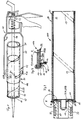
- the ring body halves 43A and 43B which are provided with gripping elements 41 on their radially inward side, are pressed slightly together, for example with one hand, so that the gripping elements 41 dig into the outer sleeve 21. If the piston 42 is now pressed further forward, the entire inner sleeve 22 together with the muzzle closure 10 serving as a handle and the sealing element 44 are advanced with respect to the outer sleeve 21, as shown.
- the piston rod 46 of the cartridge gun 40 preferably has a somewhat longer length than usual. This displacement process can already be stopped in the relative position between the inner sleeve and the outer sleeve shown in FIG. 1, because the two sleeves can then be easily separated from one another by further pulling apart. Guide elements 51 (FIG. 4) facilitate the handling of the ring body halves.
- both the mouth closure 10 and the mouthpiece 15 provided on it and the sealing element 44 consist of one and the same material, which is preferably made of the material the inner sleeve 22 is identical (Fig. 5). In this way, only two materials are used for the packaging container and can be recycled separately, apart from possibly existing, vanishingly small amounts of heat-sealable plastic.
- a film-like material can also be considered as the mouth closure 10, in particular a film material which, with that of the inner sleeve 22, is made of the same material, preferably of aluminum, whereby - again preferably - both the mouth closure and the inner sleeve are coated on their sides facing the inside of the container with a heat-weldable plastic or both are constructed from such a material.
- a film-like material can also be considered as the mouth closure 10, in particular a film material which, with that of the inner sleeve 22, is made of the same material, preferably of aluminum, whereby - again preferably - both the mouth closure and the inner sleeve are coated on their sides facing the inside of the container with a heat-weldable plastic or both are constructed from such a material.
- the inner sleeve 22 and the mouth closure 10 each consist of an aluminum foil layer 22A and a plastic surface coating 22B, preferably of polyethylene.
- the mouth closure 10 is provided with a sufficient excess so that a flange 10A covering the end face of the sleeve body 20 can form, which is held in position by a resiliently pressable ring 33 before the metal body 30 is inserted into the free sleeve end.
- the ring 33 is displaceably supported by guide rods 34 in guide bores 35 of the metal body 30 against the pressure of springs 36 and arranged in such a way that the ring 33 on the flange 10A first comes to the holding / pressing contact at the front end of the sleeve body 20 before the Ring contour 31 of the metal body 30 slides into the sleeve end.
- a known protective cap 60 shown in dashed lines in FIG. 6, made of plastic, metal or the like, can be used as a further, mechanically acting protective agent on the completely closed sleeve end be postponed.
- the film-like inner sleeve can also be produced from materials other than aluminum, such as parchment, paper or other film-like materials.
- the separate sleeves 21 and 22 can then be sent separately for recycling or disposal. If it is not possible to recycle the inner sleeve 20, in particular because of its contamination, it can be compressed to a fraction of its original volume, so that the volume to be fed to a hazardous waste landfill can be considerably reduced.
- the outer sleeve 21 is provided with at least one axially extending perforation 115 which, after emptying the packaging container, allows the independent outer sleeve 21 to be broken open and the inner sleeve 22 to be removed without being destroyed.
- a perforation 115 can easily be introduced before the packaging container is labeled.
Abstract
Description
Die Erfindung betrifft einen hülsenförmigen Verpackungsbehälter aus Mehrschichtmaterial mit den Merkmalen des Oberbegriffs von Patentanspruch 1, ein Verfahren zum Herstellen eines derartigen hülsenförmigen Verpackungsbehälters mit den Merkmalen des Oberbegriffs von Patentanspruch 9 sowie Vorrichtungen zum Herstellen eines derartigen hülsenförmigen Verpackungsbehälters gemäß den Oberbegriffen der Patentansprüche 14 und 15.The invention relates to a sleeve-shaped packaging container made of multilayer material with the features of the preamble of claim 1, a method for producing such a sleeve-shaped packaging container with the features of the preamble of claim 9 and devices for producing such a sleeve-shaped packaging container according to the preambles of
Verpackungsbehälter aus Mehrschichtmaterial haben unter anderem den Nachteil, - wenn überhaupt - dann nur mit hohem Aufwand recyclebar zu sein. Ein typischer Mehrschichtaufbau besteht aus einem auf der Innenseite mit einer Folie aus Kunststoff oder Aluminium oder einem Mehrschichtwerkstoff vollflächig kaschierten Kartonagenmaterial, das auf der Aussenseite ebenfalls mit einer dünnen Schicht, aus bedrucktem Papier, Kunststoffolie oder dergleichen vollflächig kaschiert sein kann. Wegen der Recyclingprobleme derartiger Mehrschichtmaterialien werden aus Vollkunststoff bestehende Verpackungsbehälter trotz der auch für Kunststoffe bekannten Recyclingprobleme und -kosten bevorzugt, weil reines Kartonagenmaterial für die überwiegende Zahl von Verpackungsgütern - ob nun im Lebensmittelbereich oder im Bereich chemischer Produkte, insbesondere in flüssiger oder halbflüssiger Konsistent - ungeeignet sind.One of the disadvantages of packaging containers made of multilayer material is that they can only be recycled with great effort, if at all. A typical multi-layer structure consists of a cardboard material that is fully laminated on the inside with a film made of plastic or aluminum or a multilayer material, which can also be laminated on the outside with a thin layer of printed paper, plastic film or the like. Because of the recycling problems of such multilayer materials, packaging containers made of all-plastic are preferred in spite of the recycling problems and costs also known for plastics, because pure cardboard material is unsuitable for the majority of packaging goods - whether in the food sector or in the field of chemical products, especially in a liquid or semi-liquid consistency are.
Davon ausgehend liegt der Erfindung die Aufgabe zugrunde, einen hülsenförmigen Verpackungsbehälter aus Mehrschichtmaterial zu schaffen, der auf einfache Weise recyclebar ist. Weiter wird angestrebt, daß beim Entfernen der Innenhülse keine Gefahr der Kontaminierung der verbleibenden Außenhülse besteht.Proceeding from this, the invention has for its object a sleeve-shaped packaging container made of multilayer material to create that is easily recyclable. Another aim is that when the inner sleeve is removed there is no risk of contamination of the remaining outer sleeve.
Zur Lösung dieser Aufgabe wird ein hülsenformiger Verpackungsbehälter mit den Merkmalen des Patentanspruchs 1, ein Herstellungsverfahren mit den Merkmalen des Patentanspruchs 9 sowie Herstellungsvorrichtungen mit den Merkmalen der Ansprüche 14 und 15 vorgeschlagen.To achieve this object a hülsenformiger packaging container having the features of patent claim 1, a manufacturing method having the features of claim 9 as well as making devices with the features of
Die erfindungsgemäßen hülsenförmigen Verpackungsbehälter haben unter anderem den Vorteil, daß sie vom Endverbraucher problemlos in recyclingfähige Einzelbestandteile aufteilbar sind.The sleeve-shaped packaging containers according to the invention have the advantage, among other things, that they can be easily divided into recyclable individual components by the end user.
"Hülsenförmige" Verpackungsbehälter sind im Sinne der Erfindung sämtliche Verpackungsbehälter, die aus einer mehr oder minder eigensteifen, entlang ihrer gesamten Länge gleichmäßig aus mindestens einer innenliegenden folienartigen Schutzschicht und einer bezüglich der Schutzschicht aussenliegenden Trageschicht aufgebauten Hülse (Hülsenkörper) bestehen, die mindestens an einem, vorzugsweise an beiden Enden mit einem Mündungsverschluß versehbar sind und die als fertige Hülse erst befüllt wird. Es ist gebräuchlich, die Schutzschicht und die Tragschicht als "Lagen" zu bezeichnen; vor allem die Tragschicht ist in der Regel mehrlagig. Sie unterscheidet sich damit von den - nicht gattungsgemäßen - Schlauchfolienverpackungen (EP-A2-0 151 922), bei denen ein endseitig geschlossener, bereits befüllter Folienschlauch in eine Papphülse eingeschoben wird. Grundsätzlich kann der erfindungsgemäße Hülsenkörper eine konisch zulaufende Form haben. Besonders vorteilhaft sind jedoch Hülsenkörper mit zylinderischer, das heißt über ihre gesamte Länge einen konstanten Querschnitt aufweisende Hülsenkörper von polygoner und/oder gekrümmter, wie zum Beispiel kreisrunder Außenkontur.For the purposes of the invention, "sleeve-shaped" packaging containers are all packaging containers which consist of a more or less inherently rigid, uniformly along their entire length of at least one inner film-like protective layer and a sleeve (sleeve body) constructed with respect to the protective layer on the outside, which have at least one, are preferably provided with a muzzle closure at both ends and which is only filled as a finished sleeve. It is common to refer to the protective layer and the base layer as "layers"; the base layer in particular is usually multi-layered. It differs from the - not generic - tubular film packaging (EP-A2-0 151 922), in which an already closed, filled tubular film is inserted into a cardboard tube. In principle, the sleeve body according to the invention can have a conical shape. However, sleeve bodies with a cylindrical sleeve body, that is to say with a constant cross section over their entire length, of a polygonal and / or curved, such as circular outer contour, are particularly advantageous.
Eine "folienartige Schutzschicht" im Sinne der Erfindung besteht aus einer relativ dünnwandigen, vorzugsweise aus einer Bahnenware hergestellten Schicht aus einem Material, welches das Verpackungsgut vor einem Kontakt mit der Tragschicht und damit - indirekt - auch vor einem Kontakt mit der Außenatmosphäre des Verpackungsbehälters - bzw. umgekehrt - schützt, im weitesten Sinne also eine Trennfunktion bzw. Abdichtfunktion ausübt.A "film - like protective layer" in the sense of the invention consists of a relatively thin - walled layer, preferably made of a sheet material, made of a material which protects the packaged goods from contact with the support layer and thus - indirectly - also before contact with the outside atmosphere of the packaging container . Conversely - protects, in the broadest sense therefore has a separating or sealing function.
Eine "Tragschicht" im Sinne der Erfindung gibt dem Hülsenkörper des hülsenförmigen Verpackungsbehälters eine gewisse Eigensteifigkeit gegenüber Verformungsangriffen von außen oder von innen, wie Verbiegen, Zusammendrücken, innerem Überdruck oder dergleichen.A "support layer" in the sense of the invention gives the sleeve body of the sleeve-shaped packaging container a certain inherent rigidity against deformation attacks from outside or inside, such as bending, compression, internal overpressure or the like.
Nach dem Gebrauch können die erfindungsgemäße Außenhülse und die erfindungsgemäße Innenhülse durch Drücken oder Ziehen relativ zueinander verschoben und dadurch in zwei ganze Teile von einander getrennt werden; hierzu kann ein Werkzeug nach Anspruch 16, welches auch zur Behälterentleerung mitbenutzt werden kann, oder ein länglicher Gegenstand, wie ein Hammerstiel, dienen. Bevorzugt wird der leere Hülsenkörper vorher seitlich gequetscht oder gewalkt, wobei sich die Innenhülse großflächig von der Außenhülse abhebt. Grundsätzlich ist es aber auch denkbar, daß bei dem Trennvorgang die Außenhülse oder die Innenhülse oder beide zerstört werden und danach also nicht mehr in Hülsenform vorliegen.After use, the outer sleeve according to the invention and the inner sleeve according to the invention can be displaced relative to one another by pressing or pulling and can thus be separated into two whole parts; a tool according to claim 16, which can also be used for emptying the container, or an elongated object, such as a hammer handle, can serve for this purpose. The empty sleeve body is preferably squeezed or tumbled on the side beforehand, the inner sleeve lifting off from the outer sleeve over a large area. In principle, however, it is also conceivable that the outer sleeve or the inner sleeve or both are destroyed during the separation process and are therefore no longer present in the form of a sleeve.
Die Trennung (Auseinanderziehen) des Materials der Aussenhülse vom Material der Innenhülse wird durch eine Handhabe an der Innenhülse ermöglicht, die unabhängig von der Aussenhülse angefaßt werden kann, ohne die Innenhülse vorab in einem Teilbereich, in dem sie von der Außenhülse umschlossen ist, von der Außenhülse lösen zu müssen. Eine derartige Handhabe kann zum Beispiel in einem von der Außenhülse fortweisenden Flächenstück des Materials der Innenhülse bestehen.The separation (pulling apart) of the material of the outer sleeve from the material of the inner sleeve is made possible by a handle on the inner sleeve, which can be handled independently of the outer sleeve, without the inner sleeve beforehand in a region in which it is enclosed by the outer sleeve To have to loosen the outer sleeve. Such a handle can consist, for example, in a surface piece of the material of the inner sleeve pointing away from the outer sleeve.
Eine wesentliche Vereinfachung des Zerlegens des Mehrschichtmaterials in seine Bestandteile ergibt sich durch die Merkmale des Patentanspruchs 3. Ein demgemäß als Handhabe dienender und allein mit der Innenhülse fest verbundener, mit der Außenhülse also nicht oder leicht lösbar verbundener Mündungsverschluß ist in der Regel nicht nur besonders ergonomisch, sondern gestattet die problemlose Übertragung erheblicher Kräfte, wie sie beim Verschieben zwischen Innenhülse und Außenhülse unter Umständen aufzubringen sind.A significant simplification of the disassembly of the multilayer material into its components results from the features of patent claim 3. A muzzle closure which accordingly serves as a handle and is fixedly connected solely to the inner sleeve and therefore not or easily detachably connected to the outer sleeve is not only particularly ergonomic , but allows the problem-free transfer of considerable forces, such as may have to be applied when moving between the inner sleeve and outer sleeve.
Ein stopfenartig in die Innenhülse hineinpassender Mündungsverschluß nach Patentanspruch 4 gestattet eine relativ großflächige Verbindung zwischen Mündungsverschluß und Innenhülse an der Stopfenaußenwand. Derartige Mündungsverschlüsse sind vorzugsweise als Tiefziehteile, insbesondere aus Metall, ausgebildet (Anspruch 5), wobei ein etwa vorgesehener Mündungsstutzen vorzugsweise einstückig mit dem Tiefziehteil und damit aus demselben Material wie das Tiefziehteil hergestellt wird.A muzzle closure fitting into the inner sleeve like a plug according to claim 4 allows a relatively large-area connection between the muzzle closure and the inner sleeve on the outer wall of the stopper. Mouth closures of this type are preferably designed as deep-drawn parts, in particular made of metal (claim 5), an approximately provided mouthpiece preferably being produced in one piece with the deep-drawn part and thus from the same material as the deep-drawn part.
Während nun eine Verbindung zwischen dem Mündungsverschluß und der Innenhülse auf die verschiedensten Arten denkbar ist, wird die Verwendung wärmeverschweißbarer Kunststoffe nach Patentanspruch 6 besonders bevorzugt, da dies gleichzeitig eine hohe Dichtigkeit an der Berührungskante zwischen Mündungsverschluß und Innenhülse gewährleistet und besonders einfach verarbeitbar ist, insbesondere mit einer Vorrichtung nach Patentanspruch 15. Ein Übermaß des stopfenartigen Teils des Mündungsverschlusses gemäß Patentanspruch 7 gewährleistet aufgrund der auftretenden Umfangsspannug, daß etwa vorhandene, wärmeverschweißbare Kunststoffe homogen verschweißt werden und dadurch eine völlige Dichtigkeit zwischen Mündungsverschluß und Innenhülse sowie eine besonders gleichmäßige und starke Verbindung zur Übertragung relativ hoher Kräfte von dem Mündungsverschluß auf die Innenhülse erzielt werden.While a connection between the mouth closure and the inner sleeve is conceivable in a wide variety of ways, the use of heat-weldable plastics according to claim 6 is particularly preferred, since at the same time this ensures high tightness at the contact edge between the mouth closure and inner sleeve and is particularly easy to process, in particular with a device according to
Für eine Relativverschiebung zwischen der Innen- und Außenhülse hat sich, vor allem für den Anwendungsbereich sogenannter Kartuschen zum Aufbewahren und Abspritzen mehr oder minder zähflüssiger Massen ein Spender, zum Beispiel eine Kartuschenpistole, erwiesen, der mit, insbesondere zangenförmig wirkenden, Greifelementen für die Außenhülse ausgestattet ist. Derartige Vorrichtungen sind für hülsenförmige Verpackungsbehälter nach einem der Patentansprüche 1 bis 7, insbesondere nach einem der Patentansprüche 3 bis 6 verwendbar, insbesondere dann, wenn die Vorrichtung einen die Innenhülse aus der Außenhülse herausschiebenden Kolben aufweist, dessen Kolbenstange unter Umständen aber länger als die üblicher Weise verwendeten Kolbenstangen sein muß.There has been a so-called for a relative displacement between the inner and outer sleeve, especially for the area of application Cartridges for storing and spraying more or less viscous masses have been proven by a dispenser, for example a cartridge pistol, which is equipped with gripping elements for the outer sleeve, which act in particular in the form of pliers. Devices of this type can be used for sleeve-shaped packaging containers according to one of Claims 1 to 7, in particular according to one of Claims 3 to 6, in particular if the device has a piston which pushes the inner sleeve out of the outer sleeve, but the piston rod of which may be longer than usual Piston rods used must be.
Die vorgenannten, sowie die beanspruchten und in dem nachfolgenden Ausführungsbeispiel beschriebenen, erfindungsgemäß zu verwendenden Bauteile bzw. Verfahrensschritte unterliegen in ihrer Größe, Formgestaltung, Materialauswahl und technischen Konzeptionen bzw. ihren Verfahrensbedingungen keinen besonderen Ausnahmebedingungen, so daß die in dem jeweiligen Anwendungsgebiet bekannten Auswahlkriterien uneingeschränkt Anwendung finden können.The size, shape, material selection and technical concepts and their process conditions of the aforementioned components and process steps to be used according to the invention and described in the exemplary embodiment below are not subject to any special exceptions, so that the selection criteria known in the respective field of application can be used without restriction can find.
Weitere Einzelheiten, Merkmale und Vorteile des Gegenstandes der Erfindung ergeben sich aus weiteren Unteransprüchen sowie der nachfolgenden Beschreibung der zugehörigen Zeichnung, in der - beispielhaft - ein erfindungsgemäßer hülsenförmiger Verpackungsbehälter und Vorrichtungsbauteile zu seiner Herstellung und Verwendung dargestellt sind. In der Zeichnung zeigen:
- Fig. 1 einen erfindungsgemäßen Verpackungsbehälter in Form einer Kartusche zum Aufbewahren und Abspritzen zähflüssiger und ähnlicher Massen mit einer Kartuschenpistole während eines Trennvorgangs - in einer im wesentlichen perspektivisch dargestellten Seitenansicht;
- Fig. 2 von einem Verpackungsbehälter nach Fig. 1 einen Axialschnitt zusammen mit einem aufgesetzten Herstellungswerkzeug;
- Fig. 3 eine vergrößerte Ausschnittsdarstellung eines Verpackungsbehälters nach Fig. 2;
- Fig. 4 von einer Kartuschenpistole nach Fig. 1 eine alternative Ausführungsform der Greifringkörperhälften;
- Fig. 5 von einer alternativen Ausführungsform eines Verpackungsbehälters zu Fig. 1 bis 3 das Entleerungsende im Achsialschnitt entsprechend Fig. 2 oder 3;
- Fig. 6 eine alternative Vorrichtung zum Herstellen eines Mündungsverschlusses im Achsialschnitt entsprechend Fig. 2;
- Fig. 7 eine schematische Darstellung des Herstellungsverfahrens;
- Fig. 8 einen vergrößerten Ausschnitt gemäß dem eingekreisten Detail IV in Fig. 3;
- Fig. 9 eine weitere Ausführungsform des zylinderförmigen Grundkörpers des Verpackungsbehälters und
- Fig. 10 eine Stirnansicht zu Fig. 9.
- Figure 1 shows a packaging container according to the invention in the form of a cartridge for storing and spraying viscous and similar masses with a cartridge gun during a separation process - in a side view shown essentially in perspective;
- 2 shows an axial section of a packaging container according to FIG. 1 together with an attached production tool;
- FIG. 3 shows an enlarged detail of a packaging container according to FIG. 2;
- FIG. 4 shows an alternative embodiment of the gripping ring body halves of a cartridge gun according to FIG. 1;
- 5 shows an alternative embodiment of a packaging container for FIGS. 1 to 3, the emptying end in axial section corresponding to FIG. 2 or 3;
- 6 shows an alternative device for producing a muzzle closure in axial section corresponding to FIG. 2;
- Fig. 7 is a schematic representation of the manufacturing process;
- 8 shows an enlarged detail according to the circled detail IV in FIG. 3;
- Fig. 9 shows another embodiment of the cylindrical base body of the packaging container and
- 10 is an end view of FIG. 9.
Der insgesamt mit 100 bezeichnete Verpackungsbehälter besteht aus einem im Querschnitt kreiszylindrischen Hülsenkörper 20 und einem Mündungsverschluß 10. Der Hülsenkörper 20 ist aus einem Mehrschichtmaterial hergestellt und besteht aus einer innerliegenden folienartigen Schutzschicht und einer bezüglich der Schutzschicht außenliegenden Tragschicht.The packaging container, designated as a whole by 100, consists of a
Die folienartige Schutzschicht besteht in dem dargestellten Ausführungsbeispiel aus einer auf ihrer Innenseite kunststoffbeschichteten Folie aus Aluminium, während die Tragschicht aus Kartonmaterial besteht.In the exemplary embodiment shown, the film-like protective layer consists of an aluminum-coated plastic film on its inside, while the base layer consists of cardboard material.
Die Tragschicht ist nun als eine eigenständige Außenhülse 21 ausgeführt, während die Schutzschicht als eine eigenständige Innenhülse 22 ausgeführt ist. Dies ist am besten aus Figur 1 ersichtlich, da in der dort dargestellten Situation die beiden zunächst gleichlangen Außen- und Innenhülsen relativ zueinander veschoben sind, was deshalb möglich ist, weil zwischen beiden lediglich eine kraft-, d. h. reibschlüssige Verbindung besteht.The base layer is now designed as an independent
Um einen derartigen aus zwei ineinanderliegenden Hülsen bestehenden Hülsenkörper herzustellen, wird zunächst die folienartige Schutzschicht um einen an sich bekannten Formkörper 50 gewickelt (Fig. 7), bei dem es sich für den Fall des dargestellten und insofern bevorzugten Ausführungsbeispieles um einen einseitig gelagerten Dorn handelt, um den ein zur Dornachse schräg angesetzter Streifen 121 einer Bahnenware aus kunststoffbeschichteter Aluminiumfolie fortlaufend gewickelt wird.In order to produce such a sleeve body consisting of two sleeves lying one inside the other, the film-like protective layer is first wound around a
Die Fig. 7 zeigt einen feststehenden Dorn 50, der an einem Dornträger 51 einer im übrigen nicht dargestellten, bekannten Spiralhülsenwickelmaschine angeordnet ist. Diesem Dorn 50 wird der zur Bildung der Innenhülse 22 bestimmte Streifen 21 aus Aluminiumfolie unter einem Winkel von 45° zugeführt. Durch einen ebenfalls nicht dargestellten Riemen wird dieser Streifen 21 wendelförmig auf den Dorn 50 aufgewickelt, so daß eine Art Rohr entsteht, das sich in Richtung des in Fig. 3 eingezeichneten Pfeiles bewegt. Diese Wickeltechnik zur Herstellung von Rohren ist seit vielen Jahrzehnten bekannt.FIG. 7 shows a
Um aus dem wendelförmig gewickelten, sich überlappenden Streifen 121 eine eigenständige Innenhülse 22 zu bilden, die außerdem gas- und/oder flüssigkeitsdicht ist, wurde der Streifen 121 auf seiner dem Dorn 50 zugewandten Innenseite mit einer Beschichtung 22B versehen. Bei dieser Beschichtung 22B handelt es sich vorzugsweise um einen heißsiegelfähigen Kunststoff, der zwar mit sich selbst bzw. einem entsprechenden Kunststoff verbindbar ist, nicht jedoch mit unbeschichtetem anderem Material. Damit die aus dem wendelförmig gewickelten Streifen 121 entstehende Innenhülse 22 gas- bzw. flüssigkeitsdicht wird, wird gemäß den Figuren 7 und 8 der hintere Rand 23 des die Innenhülse 22 bildenden Streifens 121 vor dem Wickelvorgang um 180° nach vorn gefaltet, so daß sich die in Fig. 8 gezeigte Situation ergibt. Die Darstellung läßt erkennen, daß auf diese Weise die Beschichtung 22B des nach vorn umgelegten hinteren Randes 23 nach außen weist, so daß sie mit der Beschichtung 22B am vorderen Rand der nachfolgenden Windung des Streifens 121 in Berührung kommt. Im Überlappungsbereich liegt demgemäß die Beschichtung 22B des umgefalteten hinteren Randes 23 unter der Beschichtung 22B des vorderen Randes, so daß der wendelförmig gewickelte Streifen 121 insgesamt durch Heißsiegeln zur Innenhülse 20 verbunden werden kann. Es entsteht somit eine eigenständige, gas- und/oder flüssigkeitsdichte Innenhülse 22, und zwar auch dann, wenn der Streifen 121 aus einer Aluminiumfolie und einer zugehörigen Trägerschicht aus Papier besteht.In order to form an independent
Auf dieser Innenhülse 22 wird anschließend sofort die Außenhülse 21 erzeugt. Zu diesem Zweck wird dem Dorn 50 das zur Bildung der Außenhülse 10 bestimmte Material zugeführt, beim Ausführungsbeispiel die vier Papierstreifen 111, 112, 113 und 114. Diese werden vor dem Zuführen auf den Dorn 50 mit Leim versehen, so daß die sich selbst und einander überlappenden Papierstreifen 111, 112, 113, 114 insgesamt zu einer eigenständigen Außenhülse 10 verleimt werden. Das Aufbringen dieser Außenhülse 10 auf der zuvor hergestellten Innenhülse 20 erfolgt ohne Zugabe von Leim oder sonstigem Bindemittel und ohne Zugabe irgendwelcher zusätzlicher Klebestreifen, so daß die Außenhülse 21 ausschließlich kraftschlüssig auf die Innenhülse 22 aufgewickelt wird. Das enge Aneinanderliegen von eigenständiger Außenhülse 21 und eigenständiger Innenhülse 22 reicht aus, diese beiden Teile des auf dem Dorn 50 gewickelten Rohres relativ zueinander festzulegen, zumal die Überlappungsbereiche eine gewisse Erhöhung der in der Trennfläche herrschenden Reibung bewirken.The
Das fortlaufend auf dem Dorn 50 entstehende Rohr wird in einzelne Abschnitte aufgetrennt, die wiederum in Einzelabschnitte aufgetrennt werden können, die der Länge des jeweils gewünschten Verpackungsbehälters entsprechen. Selbstverständlich ist es möglich, einen derartigen Behälter auf der Außenseite mit einem Etikett zu versehen.The tube continuously formed on the
Anstelle des Schrägwickelverfahrens kann für eine, vorzugshalber beide, der Teilhülsen (Innen- und Außenhülse) auch das Parallelwickelverfahren angewendet werden.Instead of the oblique winding process, the parallel winding process can also be used for one, preferably both, of the partial sleeves (inner and outer sleeve).
Grundsätzlich kann aus der Kartonagenware in entsprechender Weise wie aus der Aluminiumfolie die eigenständige Außenhülse derart schräg gewickelt werden, daß einander überlappende Berührungskanten wieder miteinander verleimt sind. Bevorzugt überlappen die Kartonagen- bzw. Papierbahnen aber einander nicht, sondern stoßen mit ihren Kanten aneinander und werden weitere Kartons bzw. Papierbahnen um die erste Karton- bzw. Papierbahn gewickelt, wobei durch versetzte Anordnung der Berührungskanten und vollflächige Beleimung zwischen den benachbarten Kartonbahnen eine eigenständige Außenhülse entsteht.Basically, the independent outer sleeve can be wound obliquely from the cardboard goods in a manner similar to that from the aluminum foil in such a way that overlapping contact edges are glued together again. However, the cardboard or paper webs preferably do not overlap one another, but rather abut one another with their edges and further cardboard or paper webs are wound around the first cardboard or paper web, with an independent arrangement of the contact edges and full-surface gluing between the adjacent cardboard webs Outer sleeve is created.
Während nun bei der bekannten Herstellung von Hülsen aus Mehrschichtmaterial die folienartige Schutzschicht auf ihrer dem Kartonagenmaterial zugewandten Seite, insbesondere mit Papier, beschichtet und durch vollflächiges Leimen mit dem Kartonagenmaterial fest verbunden wird, entfällt bei dem erfindungsgemäßen Verfahren dieser Beleimungsvorgang und kann darüberhinaus auf die Papierbeschichtung der Aluminium- oder Kunststoffolie verzichtet werden, so daß beim späteren Recyclen der Innenhülse reines oder allenfalls kunststoffbeschichtetes, nicht aber papierbeschichtetes Aluminium anfällt. Es hat sich gezeigt, daß die Formspannungen der Innenhülse 22 und der Außenhülse 21 nach dem Verlassen des Wickeldornes ausreicht, die einmal entstadene Form beizubehalten. Der so hergestellte Hülsenkörper kann in Abschnitte aufgetrennt und in üblicher Weise weiter bearbeitet und verwendet werden, weil die Haftreibung zwischen den beiden eigenständigen Hülsen hierzu ausreicht.While in the known production of sleeves from multi-layer material, the film-like protective layer on its side facing the cardboard material, in particular with paper, is coated and firmly bonded to the cardboard material by gluing over the entire surface, this gluing process is omitted in the method according to the invention and can also be applied to the paper coating of the Aluminum or plastic film are dispensed with, so that when the inner sleeve is later recycled, pure or at most plastic-coated, but not paper-coated aluminum is obtained. It has been shown that the shape stresses of the
Wie aus Figur 3 ersichtlich, ist in dem dort dargestellten Ausführungsbeispiel die Außenhülse 21 aus zwei Lagen von miteinander verleimter Kartonagenbahnen hergestellt, während die Innenhülse 22 aus einer Aluminiumschicht 22A und einer zum Hülseninneren weisenden Kunststoffschicht 22B besteht.As can be seen from FIG. 3, in the exemplary embodiment shown there, the
Der Mündungsverschluß 10 ist als Tiefziehteil aus Metallblech hergestellt und paßt mit einer nach radial außen weisenden Wandungsfläche 11 mit leichtem Übermaß stopfenartig in die Innenhülse 22 hinein. Dieses Tiefziehteil ist auf seiner dem Behälterinneren zugewandten Seite mit einer wärmeverschweißbaren Kunststoffschicht 14 versehen, welche im Bereich der zylindrischen Wandlungsfläche 11 zwangsläufig an der Kunststoffschicht 22B der Innenhülse 22 flächig anliegt (Fig. 3). Mittels eines von außen auf den auf den Hülsenkörper 20 aufgeschobenen Mündungsverschluß 10 aufsetzbaren Metallkörper 30 mit einer ihn umgebenden Heizung 32 kann eine Wärmeverschweißung der Kunststoffschicht 14 mit der Kunststoffschicht 22 A vorgenommen werden. Hierzu weist der Metallkörper eine ringförmige Außenkontur 31 auf, die zwecks bestmöglicher Wärmeübertragung so genau wie möglich an den Verbindungsrand 12 des Mündungsverschlusses 10 formangepaßt ist.The
Der Mündungsverschluß 10 kann zwar randseitig umgebördelt sein, ist aber - im Gegensatz zu der bekannten Befestigungsmethode von Mündungsverschlüssen, bei denen der Mündungsverschluß ausschließlich dadurch gehalten wird, daß er sich im Bereich einer Bördelkante in die Außenfläche der Hülse fest einkrallt - mit der Außenhülse 22 nicht fest verbunden (Fig. 3).The
Ein erfindungsgemäßer Verpackungsbehälter kann nun in üblicher Weise genutzt werden. Im Falle des dargestellten Ausführungsbeispiels also zum Beispiel mittels einer Kartuschenpistole 40 nach und nach entleert werden. Zu diesem Zweck weist die Kartuschenpistole an ihrem vorderen Ende einen Ringkörper 43 auf, gegen den sich der Mündungsverschluß 10 der Kartusche randseitig abstützt, während der Kolben 42 in der Kartusche vorgetrieben wird und ein hohlkolbenförmiges Dichtungselement 44 in Richtung auf den Mündungsverschluß 10 vortreibt und dabei den Kartuscheninhalt über einen Mündungsstutzen 15 aus der Kartusche austreibt. Um eine möglichst vollständige Entleerung der Kartusche zu gewährleisten, sind der Mündungsverschluß 10 und das Dichtungselement 44 gemäß Fig. 5 vorzugsweise an ihren aufeinander zu weisenden Flächen identisch, vorzugsweise nach außen bombiert, geformt (männlich/weiblich).A packaging container according to the invention can now be used in the usual way. In the case of the illustrated embodiment, for example, are gradually emptied by means of a
Um nun die erfindungsgemäßen Verpackungsbehälter nach ihrem Entleeren recyclen zu können, wird gemäß dem in Fig. 1 und 4 dargestellten und insofern bevorzugten Ausführungsbeispiel eine neuartige, im Bereich des Ringkörpers 43 geänderte Kartuschenpistole 40 verwendet, bei der Ringkörper 43 in zwei Ringkörperhälften 43A und 43B unterteilt ist. Diese beiden Ringkörperhälften werden beim normalen Gebrauch zum Entleeren der Kartusche durch ein einfaches (nicht dargestelltes) Sicherungselement zusammengehalten; entfernt man dieses Sicherungselement, können die Ringkörperhälften mittels ihrer federnden Haltebügel 45 soweit voneinander beabstandet werden, daß der Mündungsverschluß 10 des Verpackungsbehälters 100 durch sie hindurch paßt. Nach leichtem Vorschieben des Hülsenkörpers 20 werden die an ihrer nach radial innen weisenden Seite mit Greifelementen 41 ausgestatteten Ringkörperhälften 43A und 43B, zum Beispiel mit einer Hand leicht zusammengepreßt, so daß sich die Greifelemente 41 in die Außenhülse 21 eingraben. Preßt man nun den Kolben 42 weiter vor, so wird - wie dargestellt - die gesamte Innenhülse 22 samt des als Handhabe dienenden Mündungsverschlusses 10 und des Dichtungselementes 44 bezüglich der Außenhülse 21 vorgeschoben. Zu diesem Zweck weist die Kolbenstange 46 der Kartuschenpistole 40 vorzugsweise eine etwas größere Länge als üblich auf. Mit diesem Verschiebevorgang kann in der in Figur 1 dargestellten Relativlage zwischen Innenhülse und Außenhülse bereits aufgehört werden, weil sich die beiden Hülsen dann von Hand durch weiteres Auseinanderziehen problemlos voneinander trennen lassen. Führungselemente 51 (Fig. 4) erleichtern das Handhaben der Ringkörperhälften.In order to be able to recycle the packaging containers according to the invention after they have been emptied, a
Gewünschtenfalls ist es danach möglich, den Mündungsverschluß 10 von der Innenhülse 22 abzureißen und auch das zumeist aus Kunststoff bestehende Dichtungselement 44 aus der Innenhülse 21 herauszuschieben, so daß der Verpackungsbehälter, in seine Bestandteile völlig zerlegt problemlos den bekannten Wiederverwendungsprozessen für die einzelnen Materialien zugeführt werden kann. - Bevorzugt bestehen aber sowohl der Mündungsverschluß 10 als auch der an ihm vorgesehene Mündungsstutzen 15 sowie das Dichtungselement 44 aus ein und demselben Material, das vorzugsweise mit dem Material der Innenhülse 22 identisch ist (Fig. 5). Auf diese Weise werden - bis auf gegebenenfalls vorhandene, verschwindend geringe Mengen an wärmeverschweißbarem Kunststoff lediglich zwei Materialien für den Verpackungsbehälter verwendet und getrennt recyclebar.If desired, it is then possible to tear off the
Während sich die vorangehenden Ausführungsbeispiele vor allem auf sogenannte Kartuschen bezogen, können auch andere Mehrschicht-Verpackungsbehälter der gattungsgemäßen Art erfindungsgemäß aufgebaut sein und erfindungsgemäß hergestellt werden, insbesondere auch solche, die zum Aufbewahren von Flüssigkeiten sowie zum Aufbewahren von Lebensmitteln dienen. In Fig. 6 ist für einen derartigen Anwendungsfall in nicht maßstabsgerechter Darstellung gezeigt, daß als Mündungsverschluß 10 auch ein folienartiges Material in Betracht kommt, insbesondere ein Folienmaterial, das mit dem der Innenhülse 22 aus dem gleichen Werkstoff, vorzugsweise aus Aluminium besteht, wobei - wiederum bevorzugt - sowohl der Mündungsverschluß als auch die Innenhülse auf ihren dem Behälterinneren zugewandten Seiten mit einem wärmeverschweißbaren Kunststoff beschichtet oder beide aus einem derartigen Werkstoff aufgebaut sind. Bei dem Ausführungsbeispiel nach Fig. 6 bestehen die Innenhülse 22 und der Mündungsverschluß 10 jeweils aus einer Aluminiumfolienschicht 22A und einer Kunststoffoberflächenbeschichtung 22B, vorzugsweise aus Polyethylen. Zur Herstellung einer dichten Verbindung zwischen diesem Mündungsverschluß und dem Hülsenkörper 20 dient wiederum ein kreisförmiger Metallkörper 30, dessen radial außen liegende Ringkontur 31 in das Mündungsende des Hülsenkörpers 20 mehr oder minder stramm hineinpaßt und der mit einer Heizung 32 in dem für das Wärmeverschweissen der Kunststoffoberflächenbeschichtung 22B erforderlichen Maße beheizbar. Um der als Mündungsverschluß 10 verwendeten Folie bei dem Verschweißvorgang den erforderlichen Halt und Sitz in der richtigen Position zu verleihen, ist der Mündungsverschluß 10 mit ausreichendem Übermaß versehen, so daß sich ein die Stirnfläche des Hülsenkörpers 20 abdeckender Flansch 10A ausbilden kann, der von einem federnd andrückbaren Ring 33 in Position gehalten wird, bevor der Metallkörper 30 in das freie Hülsenende eingeschoben wird. Zu diesem Zweck ist der Ring 33 mittels Führungsstangen 34 in Führungsbohrungen 35 des Metallkörpers 30 gegen den Druck von Federn 36 verschiebbar gelagert und derart angeordnet, daß zuerst der Ring 33 am Flansch 10A zur haltenden/pressenden Anlage am Stirnende des Hülsenkörpers 20 gelangt, ehe die Ringkontur 31 des Metallkörpers 30 sich in das Hülsenende hineinschiebt. - Falls in besonderen Anwendungsfällen ein derartiger Folien-Mündungsverschluß für den Transportfall zu empfindlich ist, kann eine an sich bekannte, in Fig. 6 gestrichelt dargestellte Schutzkappe 60, aus Kunststoff, Metall oder dergleichen als weiteres, mechanisch wirkendes Schutzmittel auf das fertig verschlossene Hülsenende reibschlüssig aufgeschoben werden.While the preceding exemplary embodiments relate primarily to so-called cartridges, other multi-layer packaging containers of the generic type can also be constructed and manufactured according to the invention, in particular also those which serve for storing liquids and for storing food. In Fig. 6 for such an application, it is shown in a representation not to scale that a film-like material can also be considered as the
Es versteht sich, daß die folienartige Innenhülse auch aus anderen Werkstoffen als Aluminium, wie Pergament, Papier oder anderen folienartigen Werkstoffen hergestellt werden kann.It goes without saying that the film-like inner sleeve can also be produced from materials other than aluminum, such as parchment, paper or other film-like materials.
Um die aus den vier Papierstreifen 111, 112, 113 und 114 (Fig. 7) bestehende Außenhülse 21 getrennt von der gegebenenfalls kontaminierten Innenhülse 22 entsorgen zu können, ist es nach Entleeren des Verpackungsbehälters lediglich erforderlich, die auf ihrer Außenseite nicht mit der Innenseite der Außenhülse 21 auf irgendeine Weise verklebte oder verschweißte Innenhülse 22 in axialer Richtung aus der Außenhülse 21 herauszuziehen, und zwar mit Hilfe des Mündungsverschlusses 10, der ausschließlich mit der Innenhülse 22 verbunden ist. Dieses axiale Herausziehen der hierbei ihre Rohrform beibehaltenden Innenhülse 22 wird erleichtert, wenn zuvor die Außenhülse 21 von Hand geringfügig zusammengepreßt worden ist, um eine örtliche Trennung zwischen Innenhülse 22 und Außenhülse 21 zu bewirken. Diese Trennung ergibt sich aufgrund der Tatsache, daß die bei einem derartigen Walkvorgang verformte Innenhülse aufgrund der Verwendung der Aluminiumfolie ihre verformte Form beibehält, wogegen die dickere, aus Papier bestehende Außenhülse 21 in ihre Ausgangslage zurückkehrt. Mit Hilfe des Verschlusses kann somit die Innenhülse 22 sehr leicht aus der Außenhülse 10 in axialer Richtung herausgezogen werden.In order to be able to dispose of the
Die voneinander getrennten Hülsen 21 und 22 können anschließend getrennt einer Wiederverwertung oder Entsorgung zugeführt werden. Sollte eine Wiederverwertung der Innenhülse 20, insbesondere wegen deren Kontaminierung nicht möglich sein, kann sie auf einen Bruchteil ihres ursprünglichen Volumens komprimiert werden, so daß sich das einer Sondermülldeponie zuzuführende Volumen erheblich reduzieren läßt.The
Die Fig. 9 und 10 zeigen schließlich eine weitere Ausgestaltungsmöglichkeit des Verpackungsbehälters. In diesem Fall ist die Außenhülse 21 mit mindestens einer axial verlaufenden Perforation 115 versehen, die es nach dem Entleeren des Verpackungsbehälters gestattet, die eigenständige Außenhülse 21 aufzubrechen und die Innenhülse 22 unzerstört zu entnehmen. Eine derartige Perforation 115 kann ohne weiteres vor dem Etikettieren des Verpackungsbehälters eingebracht werden.
Claims (16)
dadurch gekennzeichnet,
characterized by
Applications Claiming Priority (2)
| Application Number | Priority Date | Filing Date | Title |
|---|---|---|---|
| DE19914123743 DE4123743A1 (en) | 1991-07-17 | 1991-07-17 | SLEEVED PACKAGING CONTAINER MULTILAYER MATERIAL, METHOD AND DEVICE FOR PRODUCING SUCH A PACKAGING CONTAINER |
| DE4123743 | 1991-07-17 |
Publications (1)
| Publication Number | Publication Date |
|---|---|
| EP0524514A1 true EP0524514A1 (en) | 1993-01-27 |
Family
ID=6436398
Family Applications (3)
| Application Number | Title | Priority Date | Filing Date |
|---|---|---|---|
| EP19920110915 Expired - Lifetime EP0523433B1 (en) | 1991-07-17 | 1992-06-27 | Method of manufacturing a cylindrically shaped packaging container |
| EP92914588A Revoked EP0596906B1 (en) | 1991-07-17 | 1992-07-11 | Sleeve-shaped packing container made of multi-layered material and process and device for making it |
| EP19920111864 Withdrawn EP0524514A1 (en) | 1991-07-17 | 1992-07-11 | Multi-layered tubular shaped packaging container and method and apparatus for the manufacturing of such a container |
Family Applications Before (2)
| Application Number | Title | Priority Date | Filing Date |
|---|---|---|---|
| EP19920110915 Expired - Lifetime EP0523433B1 (en) | 1991-07-17 | 1992-06-27 | Method of manufacturing a cylindrically shaped packaging container |
| EP92914588A Revoked EP0596906B1 (en) | 1991-07-17 | 1992-07-11 | Sleeve-shaped packing container made of multi-layered material and process and device for making it |
Country Status (9)
| Country | Link |
|---|---|
| EP (3) | EP0523433B1 (en) |
| JP (1) | JPH07500074A (en) |
| CN (1) | CN1068791A (en) |
| AT (2) | ATE135986T1 (en) |
| AU (1) | AU2312292A (en) |
| DE (3) | DE4123743A1 (en) |
| IL (1) | IL102526A0 (en) |
| WO (1) | WO1993001994A1 (en) |
| ZA (1) | ZA925188B (en) |
Cited By (2)
| Publication number | Priority date | Publication date | Assignee | Title |
|---|---|---|---|---|
| NL9300505A (en) * | 1993-03-22 | 1994-10-17 | Theodorus Johannes Maria De Ru | Packaging system, especially intended for the graphics industry. |
| WO1996031413A1 (en) * | 1995-04-07 | 1996-10-10 | Henkel Kommanditgesellschaft Auf Aktien | Cartridge |
Families Citing this family (3)
| Publication number | Priority date | Publication date | Assignee | Title |
|---|---|---|---|---|
| DE19809255B4 (en) * | 1998-03-05 | 2004-09-16 | Kkt Kaller Kunststoff Technik Gmbh | Cartridge for holding a viscous or pasty mass |
| US6358343B1 (en) | 1999-12-22 | 2002-03-19 | C. Winfield Scott | Method for manufacturing plastic drums |
| DE10006288A1 (en) * | 2000-02-14 | 2001-08-16 | Vg Nicolaus Gmbh | Cylindrical packaging for pasty filling goods |
Citations (5)
| Publication number | Priority date | Publication date | Assignee | Title |
|---|---|---|---|---|
| GB491904A (en) * | 1936-08-07 | 1938-09-12 | Dobeckmun Co | Improvements in or relating to cartons or containers for oil |
| DE1134271B (en) * | 1960-03-21 | 1962-08-02 | R C Can Company | Process for the production of a container with a telescopic lid and a device for carrying out this process |
| FR2218192A1 (en) * | 1973-01-04 | 1974-09-13 | Lincrusta | |
| US4299329A (en) * | 1979-07-09 | 1981-11-10 | Taniuchi Keiji | Extrusion cover for containers |
| EP0113160A1 (en) * | 1982-12-03 | 1984-07-11 | Ajinomoto Co., Inc. | Plastics material can |
Family Cites Families (3)
| Publication number | Priority date | Publication date | Assignee | Title |
|---|---|---|---|---|
| DE3237634A1 (en) * | 1982-10-11 | 1984-04-12 | Buck Chemisch-Technische Werke Gmbh & Co, 8230 Bad Reichenhall | Vacuum-tight container |
| EP0151922A3 (en) * | 1984-01-11 | 1986-03-05 | Teroson GmbH | Tubular bag package |
| CH681367A5 (en) * | 1990-09-12 | 1993-03-15 | Sandherr Packungen Ag |
-
1991
- 1991-07-17 DE DE19914123743 patent/DE4123743A1/en not_active Withdrawn
-
1992
- 1992-06-27 DE DE59205818T patent/DE59205818D1/en not_active Expired - Fee Related
- 1992-06-27 AT AT92110915T patent/ATE135986T1/en not_active IP Right Cessation
- 1992-06-27 EP EP19920110915 patent/EP0523433B1/en not_active Expired - Lifetime
- 1992-07-10 ZA ZA925188A patent/ZA925188B/en unknown
- 1992-07-11 AT AT92914588T patent/ATE163621T1/en not_active IP Right Cessation
- 1992-07-11 EP EP92914588A patent/EP0596906B1/en not_active Revoked
- 1992-07-11 EP EP19920111864 patent/EP0524514A1/en not_active Withdrawn
- 1992-07-11 JP JP5502561A patent/JPH07500074A/en active Pending
- 1992-07-11 AU AU23122/92A patent/AU2312292A/en not_active Abandoned
- 1992-07-11 WO PCT/EP1992/001570 patent/WO1993001994A1/en not_active Application Discontinuation
- 1992-07-11 DE DE59209220T patent/DE59209220D1/en not_active Revoked
- 1992-07-16 IL IL102526A patent/IL102526A0/en unknown
- 1992-07-16 CN CN92105780A patent/CN1068791A/en active Pending
Patent Citations (5)
| Publication number | Priority date | Publication date | Assignee | Title |
|---|---|---|---|---|
| GB491904A (en) * | 1936-08-07 | 1938-09-12 | Dobeckmun Co | Improvements in or relating to cartons or containers for oil |
| DE1134271B (en) * | 1960-03-21 | 1962-08-02 | R C Can Company | Process for the production of a container with a telescopic lid and a device for carrying out this process |
| FR2218192A1 (en) * | 1973-01-04 | 1974-09-13 | Lincrusta | |
| US4299329A (en) * | 1979-07-09 | 1981-11-10 | Taniuchi Keiji | Extrusion cover for containers |
| EP0113160A1 (en) * | 1982-12-03 | 1984-07-11 | Ajinomoto Co., Inc. | Plastics material can |
Cited By (2)
| Publication number | Priority date | Publication date | Assignee | Title |
|---|---|---|---|---|
| NL9300505A (en) * | 1993-03-22 | 1994-10-17 | Theodorus Johannes Maria De Ru | Packaging system, especially intended for the graphics industry. |
| WO1996031413A1 (en) * | 1995-04-07 | 1996-10-10 | Henkel Kommanditgesellschaft Auf Aktien | Cartridge |
Also Published As
| Publication number | Publication date |
|---|---|
| IL102526A0 (en) | 1993-01-14 |
| AU2312292A (en) | 1993-02-23 |
| ATE135986T1 (en) | 1996-04-15 |
| EP0523433A1 (en) | 1993-01-20 |
| WO1993001994A1 (en) | 1993-02-04 |
| JPH07500074A (en) | 1995-01-05 |
| ATE163621T1 (en) | 1998-03-15 |
| EP0596906B1 (en) | 1998-03-04 |
| ZA925188B (en) | 1994-02-10 |
| DE4123743A1 (en) | 1993-01-21 |
| EP0596906A1 (en) | 1994-05-18 |
| DE59209220D1 (en) | 1998-04-09 |
| EP0523433B1 (en) | 1996-03-27 |
| CN1068791A (en) | 1993-02-10 |
| DE59205818D1 (en) | 1996-05-02 |
Similar Documents
| Publication | Publication Date | Title |
|---|---|---|
| EP1644145B1 (en) | Method and device for the production of a can body, and can body | |
| DE60007963T2 (en) | Containers for holding fragile objects and method for producing such a container | |
| EP4249230A2 (en) | Method of manufacturing a pressure-resistant container | |
| DE2541912C2 (en) | Containers, in particular packaging containers, as well as a method for producing such a container and a device for carrying out the method | |
| DE2249865A1 (en) | DEVICE AND METHOD FOR PRODUCING A CONTAINER FROM A WEB OF MATERIAL | |
| DE3322977A1 (en) | PAPER CONTAINER FOR HOT FILLABLE LIQUIDS | |
| WO1995009111A1 (en) | Container made of thermoplastic material and process for producing the same | |
| DE2826680C2 (en) | Collapsible dispensing container and method for making the same | |
| EP0524514A1 (en) | Multi-layered tubular shaped packaging container and method and apparatus for the manufacturing of such a container | |
| DE2720907C2 (en) | Tube-like container and method for its manufacture | |
| EP1882637B1 (en) | Packing container | |
| AT521461B1 (en) | Flameproof can | |
| DE19741859A1 (en) | Multi-purpose can | |
| EP0447997A2 (en) | Can-like package for flowable products and method for its manufacture | |
| DE202006007686U1 (en) | Device for securing rollable transport goods on transport palette has locking elements connected via at least one coupling element, each in from of flat band and each with at least one locking element holder | |
| DE60302795T2 (en) | METHOD AND DEVICE FOR PRODUCING A TUBULAR PACKAGING | |
| EP1153837A1 (en) | Method and device for applying tubular labels to containers | |
| CH704798A2 (en) | Method and apparatus for the manufacture of can bodies and the can body. | |
| DE2243958C3 (en) | Method and apparatus for manufacturing thin-walled containers | |
| DE102011103543A1 (en) | Method for producing a tube | |
| DE1561546C (en) | Container with a receiving part and a supporting part, as well as a method for its production and a tool for carrying out the method | |
| DE102021116490A1 (en) | Cartridge with a head piece designed as a foil and a support sleeve | |
| DE1782596C3 (en) | Packaging container with a container body and a lining inserted therein, as well as a method and device for its production | |
| DE1944490C3 (en) | Stackable, dimensionally stable can | |
| DE202007017347U1 (en) | Easy-open closure element of a container |
Legal Events
| Date | Code | Title | Description |
|---|---|---|---|
| PUAI | Public reference made under article 153(3) epc to a published international application that has entered the european phase |
Free format text: ORIGINAL CODE: 0009012 |
|
| AK | Designated contracting states |
Kind code of ref document: A1 Designated state(s): PT |
|
| STAA | Information on the status of an ep patent application or granted ep patent |
Free format text: STATUS: THE APPLICATION IS DEEMED TO BE WITHDRAWN |
|
| 18D | Application deemed to be withdrawn |
Effective date: 19930728 |
|
| RIN1 | Information on inventor provided before grant (corrected) |
Inventor name: FORSTMANN, FRANK Inventor name: KIRCHBERG, KARL |