EP0523905A2 - Axiale Ausrichtung einer Bohrlehre - Google Patents
Axiale Ausrichtung einer Bohrlehre Download PDFInfo
- Publication number
- EP0523905A2 EP0523905A2 EP92306267A EP92306267A EP0523905A2 EP 0523905 A2 EP0523905 A2 EP 0523905A2 EP 92306267 A EP92306267 A EP 92306267A EP 92306267 A EP92306267 A EP 92306267A EP 0523905 A2 EP0523905 A2 EP 0523905A2
- Authority
- EP
- European Patent Office
- Prior art keywords
- coil
- axis
- drill
- portions
- sensor
- Prior art date
- Legal status (The legal status is an assumption and is not a legal conclusion. Google has not performed a legal analysis and makes no representation as to the accuracy of the status listed.)
- Granted
Links
Images


Classifications
-
- A—HUMAN NECESSITIES
- A61—MEDICAL OR VETERINARY SCIENCE; HYGIENE
- A61B—DIAGNOSIS; SURGERY; IDENTIFICATION
- A61B17/00—Surgical instruments, devices or methods, e.g. tourniquets
- A61B17/16—Bone cutting, breaking or removal means other than saws, e.g. Osteoclasts; Drills or chisels for bones; Trepans
- A61B17/17—Guides or aligning means for drills, mills, pins or wires
- A61B17/1725—Guides or aligning means for drills, mills, pins or wires for applying transverse screws or pins through intramedullary nails or pins
-
- A—HUMAN NECESSITIES
- A61—MEDICAL OR VETERINARY SCIENCE; HYGIENE
- A61B—DIAGNOSIS; SURGERY; IDENTIFICATION
- A61B17/00—Surgical instruments, devices or methods, e.g. tourniquets
- A61B17/16—Bone cutting, breaking or removal means other than saws, e.g. Osteoclasts; Drills or chisels for bones; Trepans
- A61B17/17—Guides or aligning means for drills, mills, pins or wires
- A61B17/1707—Guides or aligning means for drills, mills, pins or wires using electromagnetic effects, e.g. with magnet and external sensors
-
- G—PHYSICS
- G01—MEASURING; TESTING
- G01B—MEASURING LENGTH, THICKNESS OR SIMILAR LINEAR DIMENSIONS; MEASURING ANGLES; MEASURING AREAS; MEASURING IRREGULARITIES OF SURFACES OR CONTOURS
- G01B7/00—Measuring arrangements characterised by the use of electric or magnetic techniques
- G01B7/30—Measuring arrangements characterised by the use of electric or magnetic techniques for measuring angles or tapers; for testing the alignment of axes
- G01B7/31—Measuring arrangements characterised by the use of electric or magnetic techniques for measuring angles or tapers; for testing the alignment of axes for testing the alignment of axes
-
- A—HUMAN NECESSITIES
- A61—MEDICAL OR VETERINARY SCIENCE; HYGIENE
- A61B—DIAGNOSIS; SURGERY; IDENTIFICATION
- A61B90/00—Instruments, implements or accessories specially adapted for surgery or diagnosis and not covered by any of the groups A61B1/00 - A61B50/00, e.g. for luxation treatment or for protecting wound edges
- A61B90/39—Markers, e.g. radio-opaque or breast lesions markers
- A61B2090/3954—Markers, e.g. radio-opaque or breast lesions markers magnetic, e.g. NMR or MRI
- A61B2090/3958—Markers, e.g. radio-opaque or breast lesions markers magnetic, e.g. NMR or MRI emitting a signal
-
- Y—GENERAL TAGGING OF NEW TECHNOLOGICAL DEVELOPMENTS; GENERAL TAGGING OF CROSS-SECTIONAL TECHNOLOGIES SPANNING OVER SEVERAL SECTIONS OF THE IPC; TECHNICAL SUBJECTS COVERED BY FORMER USPC CROSS-REFERENCE ART COLLECTIONS [XRACs] AND DIGESTS
- Y10—TECHNICAL SUBJECTS COVERED BY FORMER USPC
- Y10T—TECHNICAL SUBJECTS COVERED BY FORMER US CLASSIFICATION
- Y10T408/00—Cutting by use of rotating axially moving tool
- Y10T408/16—Cutting by use of rotating axially moving tool with control means energized in response to activator stimulated by condition sensor
- Y10T408/175—Cutting by use of rotating axially moving tool with control means energized in response to activator stimulated by condition sensor to control relative positioning of Tool and work
-
- Y—GENERAL TAGGING OF NEW TECHNOLOGICAL DEVELOPMENTS; GENERAL TAGGING OF CROSS-SECTIONAL TECHNOLOGIES SPANNING OVER SEVERAL SECTIONS OF THE IPC; TECHNICAL SUBJECTS COVERED BY FORMER USPC CROSS-REFERENCE ART COLLECTIONS [XRACs] AND DIGESTS
- Y10—TECHNICAL SUBJECTS COVERED BY FORMER USPC
- Y10T—TECHNICAL SUBJECTS COVERED BY FORMER US CLASSIFICATION
- Y10T408/00—Cutting by use of rotating axially moving tool
- Y10T408/21—Cutting by use of rotating axially moving tool with signal, indicator, illuminator or optical means
-
- Y—GENERAL TAGGING OF NEW TECHNOLOGICAL DEVELOPMENTS; GENERAL TAGGING OF CROSS-SECTIONAL TECHNOLOGIES SPANNING OVER SEVERAL SECTIONS OF THE IPC; TECHNICAL SUBJECTS COVERED BY FORMER USPC CROSS-REFERENCE ART COLLECTIONS [XRACs] AND DIGESTS
- Y10—TECHNICAL SUBJECTS COVERED BY FORMER USPC
- Y10T—TECHNICAL SUBJECTS COVERED BY FORMER US CLASSIFICATION
- Y10T408/00—Cutting by use of rotating axially moving tool
- Y10T408/55—Cutting by use of rotating axially moving tool with work-engaging structure other than Tool or tool-support
- Y10T408/561—Having tool-opposing, work-engaging surface
- Y10T408/5623—Having tool-opposing, work-engaging surface with presser foot
- Y10T408/56245—Having tool-opposing, work-engaging surface with presser foot including tool-guide [or bushing]
-
- Y—GENERAL TAGGING OF NEW TECHNOLOGICAL DEVELOPMENTS; GENERAL TAGGING OF CROSS-SECTIONAL TECHNOLOGIES SPANNING OVER SEVERAL SECTIONS OF THE IPC; TECHNICAL SUBJECTS COVERED BY FORMER USPC CROSS-REFERENCE ART COLLECTIONS [XRACs] AND DIGESTS
- Y10—TECHNICAL SUBJECTS COVERED BY FORMER USPC
- Y10T—TECHNICAL SUBJECTS COVERED BY FORMER US CLASSIFICATION
- Y10T408/00—Cutting by use of rotating axially moving tool
- Y10T408/55—Cutting by use of rotating axially moving tool with work-engaging structure other than Tool or tool-support
- Y10T408/567—Adjustable, tool-guiding jig
- Y10T408/568—Guide bushing
Definitions
- the present invention relates generally to a method and apparatus for effecting alignment of two components respectively disposed externally and internally of a body and, more particularly, to a method and apparatus for aligning a surgical drill guide with a transverse opening in a femoral nail implanted in a femur.
- a common approach is to insert a tubular part called a femoral nail into the interior of the bone, and then secure it in place with one or more transversely extending screws.
- a screw hole must be drilled in the bone in direct alignment with each transverse hole in the femoral nail after the femoral nail has been inserted in the bone.
- the drill should preferably pass cleanly through the transverse hole in the femoral nail, because otherwise it will produce metal chips and shavings from the femoral nail which may impede healing and may also be a source of future discomfort or pain for the patient.
- the femoral nail is disposed inside the bone, is not possible to directly see the hole, and thus some arrangement must be provided to accurately align a surgical drill with the transverse hole through the femoral nail.
- Another traditional approach is to provide a magnetic source outside the body and a magnetic detector within the femoral nail at the transverse hole.
- the detector in the nail is coupled through wires to an indicator arrangement external to the patient, and the source of magnetism is moved until the detector indicates a maximum field, at which point it is assumed that the magnetic source is aligned with the opening in the nail.
- it is difficult to precisely detect the exact maximum of the field because the field strength is relatively uniform in the general region of the maximum.
- a certain amount of play or slop in the position of the magnetic source can occur without any significant variation in the field strength reading on the indicator arrangement, making accurate alignment difficult.
- these arrangements typically ensure that drilling starts at a point which is approximately on the axis of the transverse hole through the nail, but do not ensure that the drill is properly axially aligned with both of the diametrically opposite openings defining the transverse hole along the full length of the drill so that the drill will pass cleanly through both openings in the nail with little or no direct contact with the nail.
- an object of the present invention is to provide an arrangement capable of providing drill alignment which is substantially more accurate than that provided by known devices.
- a further object is to provide an alignment arrangement which provides precise axial alignment of the entire length of the drill along the axis of the transverse hole.
- a further object is to provide such an alignment arrangement which is easy to use.
- an apparatus which includes an arrangement for generating a magnetic field changing in strength in directions radially away from an axis, a sensor arrangement for measuring the strength of the magnetic field at a plurality of locations spaced radially from and angularly about an elongate part, and an arrangement responsive to the sensor arrangement for detecting a radial deviation of the elongate part from alignment with the axis and for providing an operator perceptible indication of a radial direction from the part to the axis.
- an apparatus for axially aligning a drill with a transverse hole in a member disposed in a body includes an arrangement in the member for generating a magnetic field which has a maximum strength along an axis of the transverse hole and which decreases in strength in directions radially away from the axis, a drill guide having an axial drill opening therethrough, first and second sensor arrangements provided at axially spaced locations on the drill guide and each having a plurality of sensors which are at angularly spaced locations and are spaced radially from the opening through the drill guide, and an arrangement responsive to the first and second sensor arrangements for detecting a deviation of the drill opening in the drill guide from coaxial alignment with the axis of the hole in the member, and for providing an operator perceptible indication of a radial direction from the drill opening to the axis.
- a further form of the present invention is a method which involves the steps of generating a magnetic field changing in strength in directions radially away from an axis, comparing the magnetic field strengths at a plurality of locations spaced radially from and angularly about an elongate part to detect a radial deviation of the elongate part from alignment with the axis, and providing an operator perceptible indication of a radial direction from the part to the axis.
- Yet another form of the invention involves an apparatus which includes a member having a first arrangement defining an axis, and a second arrangement for positioning an elongate part to extend along the axis, the second arrangement including a third arrangement on the member for generating a magnetic field, a sensor arrangement for measuring the strength of the magnetic field in the region of the elongate part, and a fourth arrangement responsive to the sensor arrangement for detecting radial deviation of the elongate part in excess of a radial deviation limit from alignment with the axis and for providing an operator perceptible indication of a radial direction from the part to the axis, wherein the fourth arrangement includes a variable gain amplifier arrangement for amplifying signals from the sensor arrangement, and an arrangement for respectively increasing and decreasing the gain of the amplifier arrangement when an output signal from the amplifier arrangement is respectively below and above respective predetermined magnitudes.
- FIG 1 is a diagrammatic view of a distal targeting system 10 embodying the present invention.
- the targeting system 10 includes a nail assembly 11 which has been inserted into a broken femur bone 12, a drill guide device 16, a conventional surgical drill 17, and an electronic control unit 18.
- the guide device 16 and nail assembly 11 are shown in more detail in Figure 2.
- the nail assembly 11 includes a femoral nail 21, which is a metal tube having at a distal end thereof a tapered end portion 22, and having at the outer end of the tapered portion a circular end hole 23.
- the femoral nail has in diametrically opposite sides thereof aligned circular openings 26A and 26B which together define a transverse hole 26 through the femoral nail.
- the femoral nail 21 has, a short axial distance from the transverse hole 26, a similar transverse hole 27.
- the femoral nail 21 is itself conventional and, in a conventional manner, is to be permanently secured in the bone 12 by two conventional and not-illustrated screws which each extend through a respective one of the openings 26 and 27 and through a respective transverse hole drilled through the bone 12 in alignment with hole 26 or 27.
- the focus of the present invention is drilling of the holes through the bone 12 in precise and accurate alignment with the holes 26 and 27 in the nail 21.
- the holes are drilled in the bone 12 with the nail 21 in place, and it is thus important that the drill pass though each of the openings 26 and 27 in the nail so as to have little or no contact with the nail itself, so that the drill does not shave from the nail small pieces of metal which may impede the healing process and may produce future pain or discomfort for the patient.
- the drill guide device 16 and control unit 18 according to the invention have therefore been developed to ensure that the drill bit 28 mounted in the chuck 29 ( Figure 2) of the drill 17 is precisely aligned with one of the openings 26 or 27 in the nail 21 as it is used to drill the associated transverse opening through the bone.
- the nail assembly 11 includes an elongate plastic sleeve 31 ( Figure 2) which is removably inserted in the femoral nail 21 and has in it a pair of aligned transverse openings defining a transverse hole 32 which is precisely coaxially aligned with the transverse hole 26.
- the tube has a similar, not-illustrated transverse hole aligned with the transverse hole 27 in the nail 21.
- An emitter coil 36 is fixedly supported within the sleeve 31 so as to be precisely coaxially aligned with the transverse holes 26 and 32 in the nail 21 and sleeve 31.
- the coil is connected by leads 37 to the control unit 18.
- a similar emitter coil 38 ( Figure 5) is provided in the sleeve 31 in precise coaxial alignment with the hole 27, and is connected at 39 to the control unit 18.
- the guide device 16 includes a cylindrical guide tube 41 which is flared at its upper end 42 so as to facilitate easy insertion therein of the drill bit 28 of drill 17.
- the tube 41 is provided with a plurality of circumferencially spaced teeth 44, which can be driven into the material of the bone 12 by striking the end 42 of the guide tube 41 with a small hammer after the guide device 16 has been properly oriented with the respect to the bone, in order to help hold the guide device 16 in that orientation.
- the guide tube 41 has concentrically fixedly mounted on it an upper disk 46 and a lower disk 47, which in the preferred embodiment are circular printed circuit boards.
- the upper disk 46 has a larger diameter than the lower disk 47.
- the upper disk 46 has mounted on its lower side four upper detecting or sensor coils 51-54 which are each spaced radially outwardly the same distance from the guide tube 41 and are provided at equal angular intervals of 90° about the guide tube 41.
- Each of the upper detecting coils 51-54 is oriented so that its axis extends parallel to the axis of the guide tube 41, and is a 1000 ⁇ H surface mount ferrite core inductor available from Toko America as type 43FS.
- Also mounted on the upper disk 46 adjacent each of the coils 51-54 is a respective conventional 0.1 ⁇ F monolithic ceramic capacitor 56-59 connected in parallel with the adjacent coil.
- the lower disk has mounted thereon four lower detecting or sensor coils 61-64 and four associated capacitors 66-69.
- the upper detecting coils 51-54 are coupled by a respective group of leads 71 to the control unit 18 of Figure 1, and the lower detecting coils 61-64 are connected by a further group of leads 72 to the control unit 18.
- An L-shaped metal bracket 76 has two legs 77 and 78, the end of leg 77 being fixedly secured to the upper disk 46 so that leg 77 extends directly radially outwardly from upper disk 46, and the leg 78 being oriented to extend upwardly from the leg 77 parallel to the axis of the guide tube 41.
- Fixedly mounted to the upper and lower ends of the leg 78 are respective vertically spaced, disk-like light emitting diode (LED) displays 81 and 82, which are of substantially of the same size and are coaxial about an axis extending parallel to the axis of the guide tube 41.
- LED disk-like light emitting diode
- the upper LED display 81 includes four LEDs of triangular shape which serve as directional arrows and are each spaced radially outwardly from a single square center LED 91, the triangular LEDs being provided at equal angular intervals of 90° about the center LED 91 and each being oriented to point radially outwardly in a direction away from the center LED 91.
- the LEDs 86-89 and 91 are all embedded in a disk-shaped plastic or synthetic resin material with their upper surfaces approximately flush with the upper surface of the plastic or resin material.
- the LEDs 86-89 and 91 are all electrically driven by the control unit 18 through a group of leads 92, and are all conventional and commercially available parts, the LEDs 86-89 being available from Panasonic Industrial Sales, Secaucus, New Jersey, as part number LN312GP, and the LED 91 being available from the same source as part number LN350GP.
- the lower LED display 82 includes four triangular or arrow-shaped LEDs 94-97 and a square center LED 99 arranged in a similar pattern and driven through an associated group of leads 100 by the control unit 18.
- control unit 18 has manually operable ZERO and CALIBRATE buttons 106 and 107, which are each a momentary push button switch. Further, a SENSITIVITY switch 108 can be set to a selected one of two positions, and an emitter coil select switch 109 can be set to one of two positions in which it respectively selects one of the emitter coils 36 and 38 disposed in the femoral nail 21.
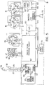
- a block diagram of the control unit 18 is shown in Figure 5, and includes a signal generator portion 111, an analog signal processing circuit 112, a computer 113, a power supply 114 which supplies power to the entire system, and a speaker 115.
- the signal generator 111 includes a conventional sine wave generator circuit 121, which outputs a sine wave signal at a frequency of substantially 16 KHz.
- the output of the sine wave generator 121 is coupled through an AC coupling capacitor 122 to a reference input of the analog signal processing circuit 112, and to an input of a sine wave amplifier 123 which includes the SENSITIVITY switch 108.
- the output of the sine wave amplifier circuit 123 can be selectively coupled through the switch 109 to one of two coaxial cables 37 and 39, which are each approximately five feet long and serve as leads for the respective emitter coils 36 and 38.
- the emitter coils 36 and 38 in the preferred embodiment are 1,000 ⁇ H inductors, and as a result of the AC signal supplied to the selected coil 36 or 38, the selected coil emits a 16 KHz alternating magnetic field, in particular an oscillating magnetic field with an axial component which changes in strength.
- the specific circuitry within the sine wave amplifier 123 of Figure 5 is shown in more detail in Figure 6, and includes an audio amplifier 126 which is a conventional and commercially available LM386N-1 integrated circuit available from national Semiconductor Corporation, Santa Clara, California. Moving the SENSITIVITY switch 108 between its two positions causes a selected one of two resistors 127 and 128 to be coupled into the circuit, the resistors 127 and 128 having different values and thus causing the sine wave amplifier circuit 123 to have one of two different gains, which in turn affects the magnitude of the AC signal supplied to the selected emitter coil and thus the strength of the magnetic field issued by that emitter coil.
- an audio amplifier 126 which is a conventional and commercially available LM386N-1 integrated circuit available from national Semiconductor Corporation, Santa Clara, California. Moving the SENSITIVITY switch 108 between its two positions causes a selected one of two resistors 127 and 128 to be coupled into the circuit, the resistors 127 and 128 having different values and thus causing the sine
- each 0.1 ⁇ F capacitor 56-59 and 66-69 and the associated coil 51-54 or 61-64 form a resonant or "tank" circuit with a resonant frequency of 16 KHz.
- the detecting coils are within the magnetic field produced by the selected emitter coil, the alternating magnetic field induces a 16 KHz signal in each of the detecting coils, which signals are supplied to the analog signal processing circuit 112.
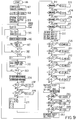
- the analog signal processing circuit 112 of the preferred embodiment is shown in more detail in Figure 7, and includes a connector 131 through which are received the eight signals from the respective detecting coils.
- the respective circuit arrangements used to process these signals from each of the eight detecting coils are effectively identical, and thus only one of the circuit arrangements is shown in detail in Figure 7.
- each signal passes through a filtering and amplification circuit 132, then a demodulation circuit 133, and then a final filtering and amplification circuit 134.
- the input signal to the filtering and amplification circuit 132 is supplied to an inverting operational amplifier 137 which is a conventional LF412A component commercially available from National Semiconductor Corporation, and which has a gain of 100.
- the 150pF capacitor in the feedback network provides single pole (-6db/octave) low pass filtering with a corner frequency of approximately 67KHz.
- the output of this amplifier is AC coupled to the input of a second inverting operational amplifier 138, which also has a gain of 100 and adds an additional pole of low pass filtering.
- the output of this amplifier is supplied to the input of a third operational amplifier which is arranged as a voltage follower, and which serves to buffer the signal being supplied to the demodulation circuit 133.
- the demodulation circuit 133 includes an AD630 demodulator, which is a conventional integrated circuit commercially available from Analog Devices, Inc., Norwood, Massachusetts, and which is configured as a synchronous detector. More specifically, the output at pin 13 is proportional to the amplitude of the component of the input signal which has the same frequency and phase as a reference signal supplied from the sine wave generator 121 ( Figure 5) through capacitor 122 and a phase shifter circuit 141 ( Figure 7). The phase shifter circuit 141 supplies the same reference signal to each of the demodulation circuits 133.
- the output at pin 13 of the AD630 can go positive or negative, depending on whether the input signal is in phase with or 180° out of phase with the reference signal.
- the output of the demodulation circuit 133 is supplied through a 10K resistor 142 to the final amplification circuit 134, where operational amplifier 143 and associated components serve as a two-pole (-12db/octave) low pass filter with a corner frequency of approximately 100Hz. It also serves as a final amplification stage.
- the resistor 142 has a value of 10K for the signals from only four of the detector coils, and has a value of 33.2K for the signals from the other four detector coils. This is because, as evident from Figure 2, the emitter coil 36 generating the magnetic field is closer to the four detector coils on lower disk 47 than to the four detector coils on upper disk 46, and thus the different values used for the resistor 142 adjust the gain of the associated final amplification circuit 134 in an appropriate manner so as to ensure the outputs of all eight final amplification circuits 134 are effectively normalized with respect to each other.
- the 150pF capacitors in the filtering and amplification circuits 132 introduce some phase shift into the respective signals passing though those circuits. Since the two input signal to each demodulation circuit 133 must ideally be either in phase or 180° out of phase, the phase shifter circuit 141 is provided simply to introduce into the 16KHz reference signal received from the sine wave generator a phase shift corresponding to that generated by each filtering and amplification circuit 132.
- the output signals from all eight final amplification circuits 134 are supplied through a connector 146 and a cable 147 ( Figure 5) to the computer 113.
- the computer 113 is a conventional and commercially available single-board computer, a variety of which are readily available from a number of manufacturers.
- the single board computer is commercially available from Octagon Systems of Riverside, Colorado as model number SBS2300H.
- the computer 113 includes an analog-to-digital (A/D) converter 151 which receives the signals on cable 147 from the analog signal processing circuit 112, a programmable read only memory (PROM) which stores the program executed by the computer, and a random access memory (RAM) 154 where the program can store variable values and other information.
- A/D analog-to-digital
- PROM programmable read only memory
- RAM random access memory
- the computer 113 has an input port to which are connected the outputs of the ZERO and CALIBRATE switches 106 and 107, and has output ports which are used to control the LEDs 86-89, 91, 94-97 and 99 on the upper and lower display disks 81 and 82.
- the computer 113 also includes an audio frequency generating arrangement 153 which drives the speaker 115.
- the frequency generating arrangement 153 includes a conventional software utility routine which is supplied with a frequency value by an application program and which toggles a dedicated digital output line of the computer at the specified frequency, the output line being coupled through a not-illustrated AC coupling capacitor and a variable resistor serving as a volume control to the speaker 115.
- the arrangement 153 could be implemented as a circuit which accepts a frequency value and generates a sine wave at the specified frequency.
- the frequency generating arrangement 153 is not in and or itself the focus of the present invention, and thus it is not illustrated and described in detail, because there are known arrangements which can be used to implement it.
- Figure 8 is a graph of a curve 156 showing how the signal strength of the magnetic field generated by the emitter coil 36 varies in a transverse direction with respect to the axis of the coil 36 at a location which is spaced axially from the coil 36 and which represents the typical axial position with respect to the coil 36 of one of the disks 46 and 47 ( Figure 2).
- the signal strength has a maximum point 157 on the axis of the coil 36, and decreases in strength with progressive movement away from the axis.
- the maximum gradient or rate of change occurs at points 158 and 159.
- Conventional systems of the type to which the invention is directed attempt to locate the point 157 of maximum field strength.
- the detecting coils in the inventive guide device 16 of Figure 2 are all offset radially from the axis of the guide tube 41 which is to be aligned with the coil 36, so that as shown in Figure 8 they are disposed approximately at the points 158 and 159 when the tube 41 is in a properly coaxially aligned relationship with the axis of the coil 36.
- the guide device 16 When using the guide device 16, a user manually holds the guide device 16 so that the tube 41 is approximately in the region of the axis of coil 36, and then watches the LED displays 81 and 82.
- the upper LED display 81 provides information regarding the accuracy of the positioning of the upper disk 46
- the lower LED display 82 provides information regarding the accuracy of the positioning of the lower disk 47. If the upper disk 46 is precisely coaxial with the axis of coil 36, then the square center LED 91 will be actuated and all of the surrounding arrow-shaped LEDs 86-89 will be off.
- the system will turn off the square center LED 91, and will light one of the LEDs 86-89 (or two of them which are adjacent) to indicate the direction in which disk 46 must be moved in order to bring it into coaxial alignment with the axis of coil 36.
- the disk 46 can be brought into coaxial alignment with the coil 36.
- the lower LED display 82 provides positional information regarding the lower disk 47.
- each disk in the inventive device defines a point of alignment, and the two spaced points of alignment together define a line, which permits accurate directional alignment of the line with the axis of the magnetic field and thus the hole through the femoral nail.
- the ZERO and CALIBRATE buttons 106 and 107 are used to zero and calibrate the system after it has been turned on and before it is used in association with a patient. Zeroing and calibration are carried out before the nail assembly 11 is implanted in a patient.
- the operator first holds the guide device 16 as far as possible from the emitter coils in the nail assembly 11, and presses the ZERO button 106.
- the system then reads and saves the states of the signals from each of the detecting coils as described in more detail below, which represents the unstimulated state of the detecting coils when they are substantially unaffected by the magnetic field being generated by an emitter coil.
- the guide device 16 is oriented in axial alignment with the emitter coil so that the end 44 of the tube 41 is spaced approximately one-half to three-quarters of an inch from the coil, and then the CALIBRATE button 107 is pressed.
- This causes the system to read and store the state of the signal actually being received from each detecting coil, and as described in more detail hereinafter, the deviations of the guide device 16 from this calibration position are thereafter measured in terms of the difference between signal strength measured by each coil and the stored calibration value of the signal strength for that coil.
- the computer initializes to zero a variable KH used to specify which of the eight channels in the A/D converter 151 (and thus which of the eight detecting coils) is currently being read. Then, at 176, the variable KH is incremented to a value of one in order to select the first analog channel, and the corresponding value in the previously-mentioned calibration variable array C is set to zero.
- Block 177 the program performs a read function (AIN) from the A/D converter 151 to obtain a digital value representing the current magnetic field strength sensed by the associated detecting coil and supplied through the analog signal processing circuit 112 ( Figure 5) to the A/D converter 151. This value is added to the value in the associated element of the calibration variable array C, and the result is stored in that element of the array.
- Block 178 indicates that block 177 is consecutively executed five times.
- the selected element of the calibration variable array ends up containing a sum of five consecutive values of signal strength read from a single detector coil. A sum of five readings is used in order to minimize the effect of momentary noise or other factors which may cause a single reading to be slightly inaccurate.
- each element of the calibration variable array C will contain the sum of five successive readings of the corresponding detector coil, and control then proceeds from block 179 to block 181, where the computer causes speaker 115 to issue a beep at 1,500Hz.
- Blocks 173 and 181 together produce beeps which to a human sound very close together and which are at different frequencies. Thus, the operator hears a two-tone beep which tells him that calibration has been performed. Thereafter, at block 182, control returns to the main program of Figure 9 at the point in which it was interrupted.
- control would proceed to a zeroing routine implemented by blocks 183-190.
- the zeroing routine is effectively identical to the calibration routine just described above, except that each sum of five readings from a given coil is loaded into a respective element of an eight-element zero variable array Z, rather than into the calibration variable array C.
- the first portion of this loop is formed by blocks 194-198, which stores for each coil a sum of five successive readings of the measured signal strength in the same general manner as already described above in association with the calibration and zeroing routines of Figure 10.
- each sum is stored in a respective element of a summation variable array SUM, rather than in the calibration array C or the zeroing array Z.
- control proceeds to block 201, where the program initializes to one an index variable N used to indicate for which of the eight detecting coils calculations are currently being performed.
- block 202 the value in the element of the zeroing array Z for the selected coil is subtracted from the corresponding value in each of the summation and calibration arrays SUM and C in order to normalize these values, the thus adjusted value from the summation array SUM is divided by the thus adjusted value from the calibration array C, and the result is stored in one of eight elements of a further variable array B.
- the index value N is then incremented, and block 203 causes block 202 to be successively executed for each of the eight coils.
- the array B contains values representative of normalized signal strengths for the respective coils, and control proceeds from block 203 to block 204.
- the program calculates a value S1, which is the sum of the absolute values of the first four elements of the array B, and calculates a value S2 which is a sum of the absolute values of the last four elements of the array B.
- the value S1 thus represents a sum of the normalized magnetic field signal strengths calculated for the four coils on the lower disk 47 ( Figure 2), and the value S2 is a similar sum for the coils of the upper disk 46.
- variables D, E and F are respectively set to three, three and zero.
- the number in variable D is expressed as a four-bit binary number
- the least significant through most significant bits respectively indicate the manner in which the arrow-shaped LEDs 94-97 are to be respectively controlled, each LED being turned on when the associated bit is a binary "1" and turned off when the associated bit is a binary "0".
- the variable E controls the four arrow-shaped LEDs 86-89 of the upper display 81.
- the variable F represents a two-bit number, the least significant bit of which controls the center LED 99 of the lower display 82, and the other bit of which controls the center LED 91 of the upper display 81.
- the guide device is properly aligned in a transverse direction extending through two diametrically opposite coils, the coils will each be at points of approximately equal signal strength on the curve 156.
- both coils would be shifted left or right in Figure 8, as a result of which one would experience a significantly higher signal strength and the other a significantly lower signal strength.
- Block 214 represents a similar comparison for the other two diametrically opposite coils on the lower disk, and blocks 217 and 219 represent similar comparisons for the two sets of diametrically opposite coils on the upper disk. If the comparison conditions in blocks 214, 217 and 219 are found to be true, appropriate adjustments are made to variable D or variable E in blocks 216, 218 and 221.
- Control then proceeds to block 222, where the program calculates for each pair of diametrically opposite coils the absolute value of the difference between the normalized signal strengths for the coils in array B, and divides this absolute value by the appropriate normalization factor LF or UF, and then stores the result in a respective difference variable DA, DB, DC or DD.
- the difference variable DA is checked to see if it is less than 0.1. If it is, then the associated coils are measuring signal strengths which are sufficiently close to each other that they will be deemed to be equal, which means the desired alignment exists in this direction, and thus at 225 a logical AND operation is performed between the variable D and the decimal number 10 (which corresponds to a binary bit pattern of "1010"), as a result of which two bits in the variable D are each forcibly set to binary "0" in order to specify that the associated diametrically-opposed arrow-shaped LEDs should be off, thus indicating that no movement in the directions corresponding to those arrows is needed to bring the guide device into alignment.
- the other difference variables DB, DC and DD are checked and, if less than 0.1, appropriate logical AND operations are carried out in one or more of the blocks 231-233.
- the decimal number 5 corresponds to a binary bit pattern of "0101", and thus forces two bits in the associated variable to 0.
- variable D is equal to 0, or in other words whether all four binary bits of this variable are equal to 0. If so, this means that all four of the LEDs on the lower display 82 will be turned off, which in turn means that the center LED 99 should be turned on. Accordingly, at block 237, a logical OR is carried out between the variable F and the decimal value 1 (which corresponds to a binary bit pattern of "01"). This forcibly sets the least significant bit in the two-bit binary value represented by variable F, in order to indicate that the center LED of 99 of the lower display should be turned on.
- Blocks 238 and 239 do the same thing for the upper display 81, the decimal value of 2 in block 239 corresponding to a binary bit pattern of "10" and thus causing the most significant bit of the 2-bit binary number in variable F to be forcibly set.
- the system calculates a sound frequency SF by dividing 300 by the sum of the difference variables DA through DD, selects (as indicated by the function symbol INT) the largest integer which does not exceed the results of the division, and places this integer in the variable SF.
- the variable SF represents an audio frequency to be output through the speaker 115 to indicate audibly to the operator the extent to which the guide device 16 is out of alignment. It will be noted that as the guide device is moved into alignment, the difference values DA through DD will all decrease toward 0, causing the result of the division in block 241 to yield progressively higher numbers. Thus, sounds at high-pitched frequencies indicate alignment, whereas sounds at low-pitched frequencies indicate substantial misalignment.
- a check is made to see if the sound frequency SF is less than 100Hz, and if so it is forced to a value of 100 at block 249 in order to ensure that the sound frequency does not drop below the minimum audible hearing range of the average person.
- the speaker 115 ( Figure 5) is used to generate an audible sound at the frequency specified by sound frequency variable SF. While the program is in the main loop, the speaker continuously generates an audible sound, the frequency of the sound being updated each time block 251 is executed. The main loop executes in a fraction of a second, and thus the operator is provided audibly and visually with rapid feedback regarding the degree of alignment or misalignment. Control then returns to the start of the main loop at block 194, and the main loop repeats.
- Figure 11 is a diagrammatic view of a portion of a system which does not utilize a computer. Portions of Figure 11 which are identical to portions of the embodiment described above are designated with the same reference numerals, including the lower disk 47, the analog signal processing circuit 112, and the LED display 82. The portion of Figure 11 which is different involves the provision of an LED control circuit 255 between the analog signal processing circuit 112 and the LED display 82, the circuit 255 essentially replacing the computer 113 of the above-described embodiment.
- Two outputs of the signal processing circuit 112 respectively corresponding to the diametrically opposite coils 61 and 63 are connected to respective inputs of a differential amplifier 256, the output of which is connected to the negative input of a further differential amplifier 257 and to the positive input of yet another differential amplifier 258, the differential amplifiers 257 and 258 serving as comparators.
- the positive input of comparator 257 is connected to a voltage divider defined by two resistors connected in series between ground and a source of power, in order to define at the positive input a predetermined threshold voltage. In a similar manner, a threshold is established at the negative input to comparator 258.
- the source of power at each voltage divider is positive or negative, as appropriate.
- the output of comparator 257 is connected to the input of a digital inverter 259, and the output of comparator 258 is connected to the input of a digital inverter 261, the outputs of the inverters 259 and 261 being connected to the diametrically opposed LEDs 94 and 96.
- the inverters 259 and 261 preferably have Schmitt-trigger input circuitry in order to provide some hysteresis in the switching characteristic.
- the amplifier 256 will produce an output of approximately zero volts, which will not exceed the threshold at either of the comparators 257 and 258, and thus they will produce output signals which are viewed as logic high signals by the gates 259 and 261, and both of these gates will produce logic low outputs which turn off the associated LEDs 94 and 96.
- the output of amplifier 256 will be a positive or negative voltage in dependance on which of the coils is sensing the larger field, and if the voltage is sufficiently positive or negative it will cause one of the comparators 257 and 258 to produce an output voltage sufficiently low to be treated as a logic low signal by the associated inverter 259 or 261, so that the inverter produces a logic high signal which causes the associated LED 94 or 96 to be illuminated in order to indicate the direction in which the disk 47 should be moved in order to equalize the field strengths measured by the two coils 61 and 63.
- a NOR gate 268 has four inputs which are each connected to the output of a respective one of the inverters 259, 261, 266 and 267, and as an output which is connected the center LED 99. If all four of the inverters are producing logic low output signals, the NOR gate will output a logic high signal which causes the center LED 99 to be illuminated.
- Figures 12 and 13 show a nail assembly 276 which is an alternative embodiment of the nail assembly 11 of Figure 2.
- the bone 12 and femoral nail 21 are the same as in Figure 2, and are therefore identified with the same reference numerals.
- a single emitter coil is split into two axially spaced portions 278 and 279, which are fixedly supported in coaxial alignment with each other on diametrically opposite sides of a tubular plastic sleeve 277.
- the sleeve 277 has diametrically opposite openings 284 and 285.
- the plastic sleeve 277 is releasably held against rotational or axial movement with respect to the nail 21 so that the coil defined by portions 278 and 279 and the openings 284 and 285 are all coaxially aligned with the openings 26A and 26B in the nail 277.
- the coil portions 278 and 279 in the illustrated embodiment are windings made from a single elongate piece of thin copper wire with an insulating coating, a portion 281 of the wire extending between the coils to electrically connect them, and portions 282 and 283 of the wire each extending away from a respective portion of the coil to serve as leads.
- An elongate cylindrical guide rod 286 can be slidably received within the sleeve 277, but is withdrawn before any hole is drilled through the bone 12.
- an alignment part 291 is provided in order to properly axially align the guide device 16 with the openings 26A and 26B through the nail assembly 277 when the CALIBRATE button 107 is to be pushed in order to calibrate the system.
- the alignment part has an elongate cylindrical rod 292, and has fixedly secured to one end of the rod a disk-like head 293.
- the diameter of the rod 292 is slightly smaller than the inside diameter of the opening through the guide tube 41.
- the alignment part 301 includes a cylindrical rod 302 and a cylindrical rod 303 which are coaxial and have a step 304 between them.
- the diameter of the rod 302 is only slightly smaller than the inside diameter of the openings 26A and 26B and the nail 12, and the rod 303 has a diameter slightly smaller than the central opening through the guide tube 41.
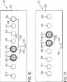
- FIGS 16-18 show an emitter unit 311 which implements an alternative embodiment of the emitter coil shown at 36 in the embodiment of Figure 2.
- the emitter unit 311 has a rectangular flexible sheet 313 made of a nonconductive material, which in the preferred embodiment is a polyimide film.
- the sheet 313 has eight circular holes 316-323 through it, the holes 316-323 being arranged in a line extending substantially the length of the sheet approximately intermediate the side edges.
- the holes have diameters which increase progressively in size from hole 316 to hole 323, although each successive increase is relatively small. Also, the spacing between adjacent holes increases progressively from the hole 316 to the hole 323, for a reason which will be explained later.
- the sheet 313 has thereon a pattern of thin and flexible copper strips or runs of relatively narrow width. These include a circular coil portion 326 of one turn provided around the hole 316 on the front of the sheet 313, spiral coil portions 327 and 328 of five turns each provided around the holes 320 and 321 on the front side of the sheet, and spiral coil portions 329 and 330 of five turns each provided around the holes 320 and 321 on the rear side of the sheet. Adjacent the hole 320 is a small plated-through hole 334 which electrically connects the radially inner end of the spiral coil portion 327 with the radially inner end of the spiral coil portion 329. A similar small plated-through hole 335 is provided adjacent the hole 321, and electrically connects the radially inner end of the spiral coil portion 328 to the radially inner end of the spiral coil portion 330.
- the copper runs also include strips which electrically connect the coils in series, such as strip 336 which is provided on the rear side of the sheet 313 and connects the radially outer ends of spiral coil portions 329 and 330.
- the copper runs include a strip 337 which connects the radially outer end of spiral coil portion 327 to one end of the circular coil portion 326, a strip 338 which connects the opposite end of the circular coil portion 326 to a plated-through connection hole 341 provided through the sheet 313 adjacent a side edge thereof, and a run 339 which connects the radially outer end of coil portion 328 to a further plated-through connection hole 342 provided adjacent the hole 334.
- the run 337 has a portion routed to extend parallel to and closely adjacent a portion of the run 338, so that electromagnetic fields generated by these adjacent portions of the runs will effectively cancel each other.
- the portions of runs 338 and 339 extending to the holes 341 and 342 are parallel and closely adjacent, and run 336 and a portion of run 339 (disposed on opposite sides of the sheet) are parallel and closely adjacent.
- the sheet 313, which is shown in an unrolled configuration in Figures 16 and 17, is rolled up during system assembly.
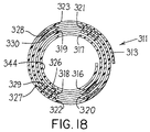
- the sheet 313 can be rolled from left to right in Figure 17 so that hole 316 overlays and is aligned with hole 318, hole 318 overlays and is aligned with hole 320, and so forth, resulting in the arrangement shown in section in Figure 18.
- the nonuniform spacing between the adjacent holes 316-323 ensures that, in the rolled configuration of Figure 18, the holes 316-323 are all coaxially aligned with each other along a common axis and collectively define a transverse cylindrical hole through the emitter roll.
- the slightly different diameters of the holes 316-323 ensure that the transverse cylindrical hole has a substantially uniform diameter despite the fact that different radial layers of the roll have different amounts of curvature.
- the thickness of the coil portions 326-330 are exaggerated in Figure 18, but it will be recognized that in practice they are very thin in relation to the sheet 313.
- the coil portions 326-330 which encircle the holes are all necessarily coaxial to the same axis as the holes, and together effectively define a single coil which is functionally equivalent to the coil shown at 36 in the embodiment of Figure 2.
- coil portion 326 has only a single turn, whereas coil portions 327-330 each have five turns, is to provide a total of 21 turns, which in turn yields the appropriate amount of inductance for the overall coil formed by all of the coil portions.
- the holes or terminals 341 and 342 are connected by wires to the control unit 18 ( Figure 1). After the wires have been connected to the holes 341 and 342 and the sheet 313 has been rolled up, it can be inserted directly into the plastic sleeve 31 ( Figure 2) so that the holes 316-323 are in alignment with the holes 32 in the sleeve 31, the sleeve 31 preventing any significant unrolling of the sheet 313.
- a strip of polyamide film with an adhesive layer on it could be wrapped circumferentially around the rolled sheet 313 in order to positively prevent it from unrolling, after which the rolled sheet with the film around it can be inserted into the sleeve 31.
- the emitter unit 311 of Figures 16-18 has the advantage of providing repeatability and reliability in yielding a given coil configuration, because the coil is an image etched from a negative rather than a wire wrapped by hand. Further, the emitter unit efficiently utilizes space, because the etching approach is superior to handwrapping in reducing air gaps, and coil portions are etched on both sides of the substrate. The reliability with which a given coil configuration can be repeated may simplify or even eliminate the need to calibrate the control circuit, because coil variances are minimized.
- the emitter unit 311 when it is in the coiled configuration of Figure 18, it has not only a transverse radial hole which is defined by holes 316-323 and through which a drill can pass, but also has perpendicular thereto a central axial hole 344 through which a guide wire or guide rod can pass.
- FIGS 19 and 20 depict an emitter unit 351 which is an alternative embodiment of the emitter unit 311 shown in Figures 16-18, and which is shown in an unrolled configuration.
- the emitter unit 351 is similar to the emitter unit 311, and therefore only the differences will be mentioned.
- the emitter unit 351 has a sheet 353 which is shorter in length than the sheet 313 of the emitter unit 311, and which has only two holes 356 and 357 therethrough.
- Respective spiral coil portions 361364 are provided around the holes 356 and 357, each coil portion having five and one half turns so that the resulting effective coil has a total of twenty-two turns.
- Two small plated-through holes 366 and 367 each adjacent a respective one of the holes 356 and 357 electrically connect the radially inner ends of the spiral coil portions provided around each of holes 356 and 357 on opposite sides of the sheet.
- a run 371 connects the radially outer ends of the coil portions 363 and 364, and two runs 372 and 373 connect the radially outer ends of the coil portions 362 and 361 to respective plated-through terminal holes 377 and 376.
- FIG 21 is a block diagram of an alternative embodiment of the control unit 18 shown in Figures 1 and 5. Similar elements have been designated with similar reference numerals, and only the differences will be described here.
- a clock signal CLK on line 391 and three programmable gain control signals PGA on line 392 are supplied from the computer 113 to the analog signal processing circuit 112.
- the PGA control lines 392 permit the computer 113 to control the gain of the analog outputs supplied by the analog signal processing circuit 112 to the A/D converter 151 in the computer 113, and the clock signal CLK on line 391 is used by the computer 113 to notify the analog signal processing circuit 112 that the programmable gain specified by line 392 is being changed, as described in more detail later.
- the computer 113 also includes, in addition to the ZERO and CALIBRATE buttons 106 and 107, a SENSITIVITY thumb-wheel 393 which is used to specify a sensitivity level, as described in more detail later.
- the sine wave amplifier shown at 123 in Figure 5 and having a sensitivity switch 108 has been replaced with a sine wave amplifier 396 which does not have a sensitivity switch and which is shown in more detail in Figure 22.
- the sine wave amplifier 396 includes most of the circuitry of the sine wave amplifier 123, except that the switch 108 and associated resistors 127 and 128 have been replaced with a single 500 0 resistor shown at 397 in Figure 22.
- the sine wave amplifier 396 also includes some additional circuitry, which is shown at 398 and includes an operational amplifier 399.
- the analog signal processing circuit 112 of Figure 21 is shown in more detail in Figure 23. Except as described below, this circuit is similar to the circuit shown in Figure 7.
- the filter and amplification circuit shown at 401 in Figure 23 includes substantially all of the components of the corresponding circuit shown at 132 in Figure 7, but also includes a programmable gain amplifier 402 provided between the operational amplifiers 138 and 139, along with associated support circuitry.
- this integrated circuit is a PGA100BG available from Burr-Brown of Arlington, Arizona.
- the amplifier 402 has an analog input INO which is coupled to the output of the operational amplifier 138, an analog output VO which is coupled to the positive input of the operational amplifier 139, amplification control inputs A3-A5 to which are applied the PGA control lines 392 received from the computer 113 through the connector 146, and a clock input CP to which is applied the clock signal CLK received from the computer 113 on line 391.
- the gain control and clock inputs are all digital inputs.
- the leading edge of a signal on the CLK line 391 clocks into the PGA 402 the gain control information present on the PGA control lines 392.
- the resistor 403 connecting the output of the modulation circuit 133 to the input of the final amplification circuit 406 has a value of 11K.
- the resistor 403 has a value of 11K for the signals from only four of the detectors coils, and has a value of 52K for the signals from the other four detector coils, as shown for example at 404.
- the final amplification circuit 406 is similar to the final amplification circuit 134 in Figure 7, except that a resistor at 407 has been changed to have a value of 100K.
- FIGs 24-27 are flowcharts representing a modified version of the program depicted in Figures 9 and 10.
- the modifications implement automatic gain control so that the computer 113 can adjust the signals received from the detector coils to provide a signal which is suitably strong but which does not saturate the input circuits of the analog to digital converter.
- program execution is started at 411 in Figure 24.
- blocks 412 and 414 are executed, which correspond to blocks 167 and 168 in Figure 9 and are therefore not described in detail.
- the central LEDs 91 and 99 ( Figure 5) of each LED display are turned off.
- the computer outputs on the PGA lines 392 a value of zero, which represents a normal gain level and will be viewed herein as being a relative gain of 1.
- the computer causes the signal on the CLK line 391 to transition from a logic low to a logic high and then back to a logic low, which in turn causes each of the PGA amplifiers 402 to accept and implement the gain specified by the PGA lines 392.
- a count value CT is initialized to zero, and a variable R is set to zero. Then, the keypad interrupt is enabled so that the computer will be interrupted when either the ZERO button 106 or the CALIBRATE button 107 is manually pressed. Then, the program begins a main program loop by proceeding to block 416.
- Control proceeds through blocks 416-419 and 421, which are similar to blocks 194-198 in Figure 9, and in which the computer reads in signals from each of the eight detection coils and stores a signal strength for each coil in a respective element of the summation variable array SUM.
- the CLK line output 391 of the computer is forced to a logic low.
- the main loop of the program was entered from block 414, where the value of the CLK line had already been set to a logic low, but in some cases control returns to the start of the main loop at block 416 with the value of the CLK line 391 at a logic high, and thus at block 422 the CLK line will be forced to a logic low.
- the count CT is incremented.
- the computer checks to see if the count value CT is greater than 2. As will become evident from the discussion which follows, if the count value CT exceeds a value of 2, it means the signals received by the computer from the detector coils are too weak to be meaningful, and should not to be used to control the LEDs. Therefore, if the count value CT is greater than 2, control proceeds to block 424, where the computer turns off all of the LEDs, generates a beep at 100 Hz, and sets the count value CT to zero. Then, control returns to the beginning of the main loop at 416.
- Figure 25 represents a portion of the program which determines whether or not the signals from the detecting coils are too weak or too strong, and thus not suitable for use in controlling the LEDs. If the signals are too weak or too strong, the computer makes an appropriate adjustment to the gain of the variable gain amplifiers 402 ( Figure 23) and then checks to see if signals of acceptable strength are being received. When signals of suitable strength are being received, control will ultimately proceed to the routine of Figure 26, which sets the LEDs in an appropriate manner. On the other hand, whenever it is determined in Figure 25 that the signal strengths are not currently acceptable, control is returned to the beginning of the main loop. For purposes of evaluating signal strength, the signal from one of the coils on the lower disk 47 ( Figure 2) is used, the normalized signal strength for which is located in array element B(5).
- the computer checks to see if the variable R has a value of 1.
- the variable R normally contains the gain control value PGA which was in effect at the point in time when the indicator LEDs were most recently updated. During normal operation, the variable R will thus usually contain a value which is the same as the gain control value PGA, but if the gain value is changed then the variable R will be different from the gain until such time as the routine controlling the indicator LEDs is again executed, because the variable R is loaded with the gain value PGA at the end of the routine controlling the LEDs.
- variable R will have been initialized to 0, and thus control will proceed from block 431 to block 432, where the computer will check to see if the count CT has a value of 1 and the absolute value of the signal strength from the selected coil is above a minimum acceptable signal strength of 0.3. If so, then the magnitude of the signal strength is sufficient to serve as a basis for controlling the LEDs, and control proceeds to block 433, where the system outputs on the gain control lines PGA a value of 0, (corresponding to a relative gain of 1), and sets the CLK line 391 to a logic high to load this gain value into the programmable gain amplifiers 402 ( Figure 23). Then, the count CT is reset to 0, and control proceeds at 434 to the routine of Figure 26, which controls the LEDs and will be described in more detail later.
- control proceeds to block 436, where the conditions will not be met during this pass because the count value CT will be 1 rather than 2, and control then proceeds to block 437, where the computer checks to see if the count value CT is 1 and the absolute value of the signal strength B(5) is between values of 0.1 and 0.3. If the signal strength is between these values, then it is currently too low to be used in controlling the LEDs, but could possibly be acceptable if the gain were increased. Therefore, control proceeds to block 438, where the computer outputs on the gain control lines PGA a value of 1 (representing a relative gain of 2), and then sets the CLK line 391 to a logic high to load the new gain setting into the amplifiers 402 ( Figure 23).
- Control then returns at 439 to the start of the main loop at block 416 in Figure 24.
- the CLK output is returned to a logic low and the count value CT is incremented from a value of 1 to a value of 2.
- control will proceed from block 431 to block 432, and because the count variable CT now contains a value of 2, control will proceed from block 432 to block 436.
- the computer checks to see if the count CT is 2 and if the absolute value of the signal strength is now greater than the value 0.3.
- control proceeds to block 441, where the computer outputs a value of 1 on the gain control lines PGA, sets the CLK signal to a logic high to load the new gain value into the amplifier, and then sets the count value CT to 0. Control then proceeds at 434 to the LED control routine.
- the LED control routine Once the LED control routine has been executed with the higher gain, the variable R will be loaded with the PGA value of 1, and thus when the routine of Figure 25 is entered again, control would proceed from block 431 to block 442.
- a value K(5) which is described later and represents the maximum expected signal strength from the detector coil monitored by the routine of Figure 25, is multiplied by a value of 1.025 in order to obtain an upper limit value slightly in excess of the maximum expected value, and the upper limit value is stored in a variable X(5).
- Control then proceeds to block 443, where the computer checks to see if the count value CT is 1 (meaning that the gain has not just been changed) and whether the absolute value of the measured signal strength B(5) is between 0.3 and the upper limit in variable X(5). If it is, then control proceeds to block 444, where the system controls the PGA lines and the CLK line so as to ensure that the higher gain setting is in fact in effect, and then clears the count value CT. Control then proceeds at 434 to the LED control routine.
- control proceeds to block 446, where the computer checks to see if the count value CT has a value of 1 and the absolute value of the signal strength B(5) is in excess of the upper limit in variable X(5). If these conditions are met, then the signal is so strong that it could saturate some circuitry and produce erroneous results. Accordingly, control proceeds to block 447, where a value of 0 is output on the PGA lines and the CLK output line is set to a logic high, which causes the amplifier 402 ( Figure 23) to change from a relative gain of 2 back to a relative gain of 1. Control then returns at 439 to the main routine without entry to the LED control routine.
- control proceeds to blocks 448 and 449, where the conditions will not usually be met because the count variable CT will normally have a value of 1.
- control will reach block 451, where the computer will check to see if the count variable CT is 1 and the absolute value of the signal strength B(5) is below the value of 0.3. If these conditions are met, it means that the system is operating at the increased gain level but the received signal strength is still not strong enough to be used to control the indicator LEDs, and thus control proceeds to block 452 where the count variable CT is set to a value of 3 and a beep is generated at 100 Hz to notify the system operator that the signal strength is insufficient. Control is then returned at 439 to the beginning of the main loop at block 416. Subsequently, at block 423, it will be determined that the count variable CT has a value greater than 2, and block 424 will be executed to turn off all of the indicator lights.
- control proceeds to block 453, where the computer uses the PGA and CLK lines to ensure that the lower gain is in fact in effect, and clears the count variable CT. Control then proceeds at 434 to the routine which controls the indicator LEDs.
- control would proceed through block 449 to block 454, where the computer verifies that the count variable CT has a value of 2 and checks to see if the absolute value of the signal strength B(5) is below the minimum acceptable value of 0.3. If these conditions are met, it means that the reduction in gain has taken the signal strength from a value in excess of the upper limit at the higher gain to a value below the minimum acceptable level of 0.3 at the lower gain. Therefore, the LEDs cannot be accurately updated and control proceeds to block 452.
- Blocks 433, 441, 444 and 453 all represent circumstances under which control proceeds to the routine of Figure 26, which controls the indicator LEDs.
- execution begins at block 461, which is identical to block 204 in Figure 9, except that it also sets the CLK line 291 back to a logic low (to complete the pulse on the CLK line which was initiated when it was set to a logic high in one of the blocks 433, 441, 444 and 453 of Figure 25).
- Blocks 462-475 are identical to blocks 206-209, 211-214, 216-219 and 221-222 in Figure 9, and are therefore not described here in detail.
- control proceeds to block 476, where the computer reads the setting of the thumbwheel 393 ( Figure 21), adds one to this value, divides the sum by 480, and stores the result in a variable DEADB which represents a deadband value.
- the deadband value DEADB defines a radial deviation limit.
- Control then proceeds to block 481.
- Blocks 481-488 are identical to the blocks 224-228 and 231-233 of Figure 9, except that the values DA, DB, DC and DE are each being compared to the variable DEADB rather than a fixed value of 0.1.
- the comparisons in blocks 481, 483, 485 and 487 represent the extent to which signal magnitudes from two opposed coils can shift away from equal readings before the computer concludes that a center LED should be turned off and one of the arrow-shaped LEDs should be turned on to indicate a needed positional correction of the drill guide. Stated differently, these comparisons determine how far the drill guide can be moved out of axial alignment in a radial direction before an arrow LED is illuminated. It will thus be recognized that, by adjusting the thumbwheel, the value in the variable DEADB can be changed, which in turn adjusts the extent to which the drill guide can be moved away from axial alignment before one of the arrow LEDs is illuminated. Thus, changing the value on the thumbwheel changes the sensitivity of the system.
- Blocks 491-494 are effectively identical to blocks 236-239 in Figure 9, and are not described here in detail.
- the drill guide is usually spaced from the emitter coil, and the signals from the detector coils on the lower disk 47 ( Figure 2) are sufficiently strong but the signals from the detector coils on the upper disk 46 are too weak. Therefore, when operating at the increased gain, the signals from the detector coils on the upper disk are ignored, and consequently the LEDs on the upper disk-like display 81 ( Figure 2) are all turned off, and only the LEDs on the lower display 82 are utilized.
- control proceeds to block 497 where the computer sets the variable D to zero in order to turn off the arrow-shaped LEDs for the upper display 81, and clears the bit in variable F which controls the center LED for the upper display 81 in order to turn off this center LED.
- Control then proceeds to block 501.
- Blocks 501-508 are identical to blocks 241-243, 246-249 and 251 in Figure 9, and are therefore not described here in detail.
- control proceeds to block 509, where the variable R is loaded with the current PGA value to reflect the fact that the LED control routine has been executed at least once with the system operating at the gain now specified by variable R. Control then returns at 510 to the beginning of the main routine at block 416 in Figure 24.
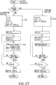
- Figure 27 is a flowchart of the interrupt service routine executed when either the ZERO button 106 or the CALIBRATE button 107 is manually pressed.
- the interrupt service routine of Figure 27 is identical to the interrupt service routine of Figure 10, except for the following differences.
- Block 512 in Figure 27 corresponds to block 173 of Figure 10, in that it includes generation of a beep at 1000 Hz, but in addition it sets the count value CT to 0, sets the variable R to 0, outputs a 0 on the PGA lines 392 in order to force the system to a relative gain of 1 for purposes of calibration, and changes the CLK line 391 to a logic high and then back to a logic low in order to clock the new gain into the gain amplifiers 402 ( Figure 23) and thus forcibly implement a relative gain of 1.
- Block 513 in Figure 27 corresponds to block 183 in Figure 10, in that it generates a beep at 1000 Hz, but in addition it outputs a 0 on the PGA lines 392 and then successively outputs a logic high and logic low on the CLK line 391 in order to forcibly implement a relative gain of 1.
- Block 514 in Figure 27 corresponds to block 177 in Figure 10, in that each of the eight elements in the C array is loaded with data which represents a signal strength from the corresponding detector coil.
- the value in the element of the zeroing array Z for each coil is subtracted from the corresponding value in each of the summation and calibration arrays SUM and C in order to normalize these values, the thus adjusted value from the summation array SUM is divided by the thus adjusted value from the calibration array C, and the result is stored in one of the eight elements of a variable array K.
- the data in the array K is thus similar to the data loaded into the array B in block 427 of Figure 24, in that the values in each case represent normalized signal strengths for the respective coils.
- the detector coils will be as close to the emitter coil as they are normally permitted to get, and thus the values in the array K represent the maximum signal strengths which the detector coils should ever experience from the emitter coil.
- the maximum value in array element K(5) is used in block 442 of Figure 25 to determine the upper limit value placed in variable X(5).
- Figures 28 and 29 shown an alternative embodiment of the guide device 16 of Figure 1.
- a plastic housing 521 has a teardrop-shaped upper portion 523, and a handle portion 522 extending horizontally outwardly from the pointed end of the teardrop-shaped upper portion.
- a downwardly converging frustoconical lower portion 524 extends downwardly from the underside of the upper portion 523.
- a cylindrical sleeve 526 extends vertically through the housing, and is secured to top and bottom walls 527 and 528 of the housing.
- Disks 531 and 532 each having thereon four detector coils are mounted at vertically spaced locations on the sleeve 526 within the housing.
- a vertically extending guide tube 536 has an upper portion 537 with an outside diameter slightly less than the inside diameter of the sleeve 526, and has a lower portion 538 with an outside diameter substantially equal to the outside diameter of sleeve 526.
- An annular step 539 is located between the portions 537 and 538.
- the tube 536 has at its lower end a plurality of teeth 541, and has a central opening 542 of uniform diameter extending vertically therethrough.
- the upper portion 537 is removably slidably inserted into and has approximately the same axial length as the sleeve 526, the annular step 539 being disposed against the lower end of the sleeve 526.
- the tube 536 can be manually withdrawn from sleeve 526, and replaced with other tubes which are identical to tube 536 except that the lower portion 538 of each has a longer or shorter axial length.
- an appropriate tube is selected so that the axial length of the lower portion corresponds to the depth of tissue or muscle through which the guide must be inserted to reach the bone, a longer length being used for patients with a thick layer of tissue, and shorter lengths for patients with progressively thinner layers of muscle and tissue.
- the LEDs 546-550 corresponding to the upper disk 531 and the LEDs 551-555 corresponding to the lower disk 532 are provided in the top wall 527 of the housing 521 on opposite sides of the sleeve 526.
- a cable 557 exits from the handle portion 522 and contains wires which are coupled to the LEDs and to the detector coils.
- the housing 521 has two different color bands 558 and 559 on the exterior thereof, which respectively represent the upper and lower detector disks 531 and 532 disposed inside the housing.
- the LEDs 546-550 for the upper disk 531 all have the same color as the upper color band 558
- the LEDs 551-555 for the lower disk 532 all have the same color as the lower color band 559.
- Figure 30 is a top view of a portion of an alternative embodiment of the housing 521 of Figure 28, the modified housing including a top wall 571 having a cylindrical vertical sleeve 572 which is equivalent to the sleeve 526 of Figure 29.
- An inner ring of LEDs includes four arrow-shaped LEDs 581-584 at equally spaced angular intervals, with small circular LEDs 585 therebetween.
- An outer ring includes four arrow-shaped LEDs 576579 with small circular LEDs 580 therebetween. The rings are concentric about the sleeve 572.
- the LEDs 576-580 correspond to the upper disk in the housing, and the LEDs 581-585 correspond to the lower disk.
- the housing has color bands similar to those shown at 558 and 559 in Figure 28 and the respective rings of LEDs have respective colors corresponding to the respective color bands, but it will be recognized that it would be possible to use a common color for the LEDs of both rings and omit both color bands.
- the drill guide device 16 After turning on the system of Figure 1, and before installing the femoral nail 21 in the bone of a patient, the drill guide device 16 is first held at a location very remote from the femoral nail 21 and thus remote from the magnetic field being generated around the femoral nail 21, and the ZERO button 106 is pressed. Then, with reference to Figure 14, the cylindrical rod 292 of the alignment part 291 is inserted through the opening in the guide tube 41 of guide device 16, and then the lower end of rod 292 is inserted through the openings 26A and 26B in the femoral nail 12 so that the nail 12 and the lower end of rod 292 each engage an upwardly facing surface 294.
- the upper end of the guide device 16 is maintained against the underside of the head 293 either manually or by friction between the guide tube 41 and rod 292, so that the lower end 44 of the guide tube 41 is spaced a predeterminded distance from the upper end of nail 12.
- the alignment part 301 of Figure 15 could be used, in particular by inserting the rod 302 through the openings 26A and 26B with a very close fit therebetween, orienting the parts so that the nail 12 and lower end of rod 302 engage the surface 294, and then slipping the guide device 16 over the rod 303 so that the lower end 44 of the guide tube 41 engages the step 304.
- the lower end 44 of the guide tube 41 is spaced the same predetermined distance from the nail 12 as in Figure 14.
- the CALIBRATE button 107 is pressed. Thereafter, the nail assembly 11 is driven lengthwise into the patient's femur.
- the drill guide 16 ( Figure 2) is then manually held close to the surface of the patient's leg, and its position is varied while the LEDs are visually observed.
- the SENSITIVITY switch 108 can be set to select an appropriate gain reflecting the distance from the skin surface to the bone.
- Illuminated arrow-shaped LEDs indicate the directions in which the guide device 16 must be moved in order to achieve axial alignment with the transverse hole in the implanted femoral nail, and making these movements will eventually bring the tube 41 of the drill guide into proper axial alignment, at which point only the central LEDs 91 and 99 will be illuminated.
- the location on the patient's leg beneath the drill guide is then marked, an incision is made, and retractors are used to keep the incision open.
- the drill guide is then brought closer and is again positionally adjusted until it is in proper alignment and only the central LEDs 91 and 99 are lit.
- the end 42 or the drill guide can be tapped with a hammer in order to drive the teeth into the bone and thus hold at least the lower end of the drill guide in position, but it is not a requirement that the teeth 44 be used in this manner.
- the drill 17 is used to drill a hole through the bone 12.
- the switch 109 is then flipped so as to energize the other emitter coil, and then the steps outlined in this paragraph are repeated in association with the other hole 27 (Figure 1) in the femoral nail.
- the conventional and not-illustrated structure which physically interconnects the sleeve 31 to the femoral nail 21 at the proximal end of the femoral nail at the end of the bone is then released, and the sleeve 31 and the coils supported by it are all withdrawn from the femoral nail. Then, self-tapping distal screws are screwed into each of the two screw holes drilled in the bone, each screw passing through a respective one of the transverse holes 26 and 27 ( Figure 1) in the femoral nail in order to securely hold it in place.
- a nail guide rod 286 is driven into the femur. Then, the nail assembly 276 is coaxially oriented around the exposed end of the rod 186, and is driven into the femur over the rod 286. Then, the rod 286 is extracted.
Applications Claiming Priority (4)
| Application Number | Priority Date | Filing Date | Title |
|---|---|---|---|
| US72765291A | 1991-07-09 | 1991-07-09 | |
| US727652 | 1991-07-09 | ||
| US83967192A | 1992-02-19 | 1992-02-19 | |
| US839671 | 1992-02-19 |
Publications (3)
| Publication Number | Publication Date |
|---|---|
| EP0523905A2 true EP0523905A2 (de) | 1993-01-20 |
| EP0523905A3 EP0523905A3 (en) | 1993-05-12 |
| EP0523905B1 EP0523905B1 (de) | 1996-10-02 |
Family
ID=27111554
Family Applications (1)
| Application Number | Title | Priority Date | Filing Date |
|---|---|---|---|
| EP92306267A Expired - Lifetime EP0523905B1 (de) | 1991-07-09 | 1992-07-08 | Axiale Ausrichtung einer Bohrlehre |
Country Status (6)
| Country | Link |
|---|---|
| US (1) | US5584838A (de) |
| EP (1) | EP0523905B1 (de) |
| JP (1) | JPH0698894A (de) |
| AT (1) | ATE143580T1 (de) |
| CA (1) | CA2073266A1 (de) |
| DE (1) | DE69214219D1 (de) |
Cited By (14)
| Publication number | Priority date | Publication date | Assignee | Title |
|---|---|---|---|---|
| EP0628287A2 (de) * | 1993-05-20 | 1994-12-14 | Maurizio Luigi Valsecchi | Magnetische Vorrichtung zur Feststellung der Lage und der Orientierung eines Lochs durch einen Marknagel |
| US5411503A (en) * | 1993-06-18 | 1995-05-02 | Hollstien; Steven B. | Instrumentation for distal targeting of locking screws in intramedullary nails |
| WO1997013467A1 (en) * | 1995-10-13 | 1997-04-17 | Lucio Catamo | Probe for locating holes in orthopaedic internal fixation devices |
| EP0897289A1 (de) * | 1996-05-06 | 1999-02-24 | Wright Medical Technology, Inc. | Magnetische positionierungsvorrichtung für schrauben zur orthopödischen fixation |
| DE20015775U1 (de) * | 2000-09-12 | 2002-01-31 | Stryker Trauma Gmbh | Knochennagel |
| US7029478B2 (en) * | 2003-09-30 | 2006-04-18 | Depuy Products, Inc. | Method and apparatus for distal targeting of locking screws in intramedullary nails |
| WO2008105874A1 (en) * | 2007-02-28 | 2008-09-04 | Smith & Nephew, Inc. | Instrumented orthopaedic implant for identifying a landmark |
| WO2008106593A3 (en) * | 2007-02-28 | 2008-11-13 | Smith & Nephew Inc | System and method for identifying a landmark |
| WO2015018877A1 (en) * | 2013-08-06 | 2015-02-12 | Point Targeting Ag | Surgical guidance system for orthoscopic drilling |
| US9031637B2 (en) | 2009-04-27 | 2015-05-12 | Smith & Nephew, Inc. | Targeting an orthopaedic implant landmark |
| ITCZ20130022A1 (it) * | 2013-12-09 | 2015-06-10 | Pietro Arcidiacono | Sistema e metodo di allineamento di chiodi endomidollari |
| US9763598B2 (en) | 2009-04-27 | 2017-09-19 | Smith & Nephew, Inc. | System and method for identifying a landmark |
| US9775649B2 (en) | 2008-02-28 | 2017-10-03 | Smith & Nephew, Inc. | System and method for identifying a landmark |
| US9827112B2 (en) | 2011-06-16 | 2017-11-28 | Smith & Nephew, Inc. | Surgical alignment using references |
Families Citing this family (80)
| Publication number | Priority date | Publication date | Assignee | Title |
|---|---|---|---|---|
| US6074394A (en) * | 1997-01-28 | 2000-06-13 | Krause; William R. | Targeting device for an implant |
| US6036696A (en) * | 1997-12-19 | 2000-03-14 | Stryker Technologies Corporation | Guide-pin placement device and method of use |
| US6503249B1 (en) * | 1998-01-27 | 2003-01-07 | William R. Krause | Targeting device for an implant |
| US6153884A (en) * | 1998-06-11 | 2000-11-28 | Seimans Automotive Corporation | Radioisotope proximity sensor |
| US6162228A (en) * | 1999-07-20 | 2000-12-19 | Durham; Alfred A. | Device for magnetically targeting locking holes in orthopedic hardware |
| AU7940900A (en) | 1999-11-10 | 2001-06-06 | Eeg, Ltd. | Method for locating holes in orthopaedic devices |
| US6342057B1 (en) | 2000-04-28 | 2002-01-29 | Synthes (Usa) | Remotely aligned surgical drill guide |
| US6379364B1 (en) | 2000-04-28 | 2002-04-30 | Synthes (Usa) | Dual drill guide for a locking bone plate |
| US6656189B1 (en) | 2000-05-25 | 2003-12-02 | Synthes (Usa) | Radiolucent aiming guide |
| US20040087877A1 (en) | 2000-08-23 | 2004-05-06 | Besz William John | Catheter locator apparatus and method of use |
| US6658300B2 (en) | 2000-12-18 | 2003-12-02 | Biosense, Inc. | Telemetric reader/charger device for medical sensor |
| US6638231B2 (en) | 2000-12-18 | 2003-10-28 | Biosense, Inc. | Implantable telemetric medical sensor and method |
| US6746404B2 (en) * | 2000-12-18 | 2004-06-08 | Biosense, Inc. | Method for anchoring a medical device between tissue |
| US6783499B2 (en) | 2000-12-18 | 2004-08-31 | Biosense, Inc. | Anchoring mechanism for implantable telemetric medical sensor |
| US6652464B2 (en) | 2000-12-18 | 2003-11-25 | Biosense, Inc. | Intracardiac pressure monitoring method |
| ES2325612T3 (es) * | 2000-12-22 | 2009-09-10 | Tyco Healthcare Group Lp | Tornillo de sutura. |
| US6887245B2 (en) * | 2001-06-11 | 2005-05-03 | Ge Medical Systems Global Technology Company, Llc | Surgical drill for use with a computer assisted surgery system |
| US7060075B2 (en) * | 2002-07-18 | 2006-06-13 | Biosense, Inc. | Distal targeting of locking screws in intramedullary nails |
| US6665948B1 (en) | 2002-09-05 | 2003-12-23 | Scott Hal Kozin | Drill bit penetration measurement system and method |
| JP4759266B2 (ja) * | 2002-10-03 | 2011-08-31 | ヴァージニア テック インテレクチュアル プロパティーズ,インコーポレイテッド | 磁気標的装置 |
| EP1545343A2 (de) * | 2002-10-03 | 2005-06-29 | Virginia Tech Intellectual Properties, Inc. | Magnetische zielvorrichtung |
| US20040152955A1 (en) * | 2003-02-04 | 2004-08-05 | Mcginley Shawn E. | Guidance system for rotary surgical instrument |
| US20040171930A1 (en) * | 2003-02-04 | 2004-09-02 | Zimmer Technology, Inc. | Guidance system for rotary surgical instrument |
| US7239811B2 (en) * | 2003-02-18 | 2007-07-03 | Victor Company Of Japan, Ltd. | Optical-axis directional indicating apparatus for optical communication |
| DE20314742U1 (de) * | 2003-09-24 | 2003-12-04 | Stryker Trauma Gmbh | Zielgerät für einen Verriegelungsnagel sowie Verriegelungsnagel |
| GB0405013D0 (en) * | 2004-03-05 | 2004-04-07 | Depuy Int Ltd | Implantable marker instruments and methods |
| US8114086B2 (en) | 2004-03-08 | 2012-02-14 | Zimmer Technology, Inc. | Navigated cut guide locator |
| US7993341B2 (en) * | 2004-03-08 | 2011-08-09 | Zimmer Technology, Inc. | Navigated orthopaedic guide and method |
| DE502004004083D1 (de) * | 2004-05-05 | 2007-07-26 | Brainlab Ag | Marknagel-Tracking |
| US7447565B2 (en) * | 2004-05-06 | 2008-11-04 | John Cerwin | Electronic alignment system |
| ITTO20040292A1 (it) * | 2004-05-06 | 2004-08-06 | Ezio Visentin | Organo di collegamento atto ad essere introdotto all'interno di una struttura ossea di un corpo umano o animale e sistema per il rilevamento di almeno un punto di riferimento prestabilito nell'organo di collegamento stesso. |
| US7481815B2 (en) | 2004-09-23 | 2009-01-27 | Synthes (U.S.A.) | Coplanar X-ray guided aiming arm for locking of intramedullary nails |
| US20060085005A1 (en) * | 2004-10-01 | 2006-04-20 | Kenealy James N Iii | Bone drill system with highly visible depth markings |
| US7976518B2 (en) | 2005-01-13 | 2011-07-12 | Corpak Medsystems, Inc. | Tubing assembly and signal generator placement control device and method for use with catheter guidance systems |
| EP1861021A1 (de) * | 2005-03-17 | 2007-12-05 | Smith and Nephew, Inc. | Positionierungssystem für ein medizinisches befestigungselement |
| DE102005014573A1 (de) * | 2005-03-31 | 2006-10-12 | Stryker Trauma Gmbh | Datenübertragungssystem in Verbindung mit einem Implantat |
| US9192398B2 (en) * | 2005-09-19 | 2015-11-24 | DePuy Synthes Products, Inc. | Orthopedic implant insertion handle and aiming guide |
| US7520880B2 (en) * | 2006-01-09 | 2009-04-21 | Zimmer Technology, Inc. | Adjustable surgical support base with integral hinge |
| US7744600B2 (en) | 2006-01-10 | 2010-06-29 | Zimmer Technology, Inc. | Bone resection guide and method |
| US7727240B1 (en) | 2006-02-15 | 2010-06-01 | Blake Benton | Method and system for securing an intramedullary nail |
| US20070239153A1 (en) * | 2006-02-22 | 2007-10-11 | Hodorek Robert A | Computer assisted surgery system using alternative energy technology |
| EP2081506B1 (de) * | 2006-06-29 | 2010-09-08 | L.r.s. Ortho Ltd. | System zur lokalisation von distalen löchern eines marknagels |
| DE602006018666D1 (de) * | 2006-08-15 | 2011-01-13 | Ao Technology Ag | Vorrichtung für die computergestützte distale arretierung von marknägeln und verfahren für die lokalisierung der distalen verriegelungslöcher von marknägeln |
| US8197494B2 (en) | 2006-09-08 | 2012-06-12 | Corpak Medsystems, Inc. | Medical device position guidance system with wireless connectivity between a noninvasive device and an invasive device |
| US7785330B2 (en) * | 2006-09-11 | 2010-08-31 | Depuy Products, Inc. | Method and apparatus for distal targeting of locking screws in intramedullary nails |
| US20080108995A1 (en) * | 2006-11-06 | 2008-05-08 | Janet Conway | Internal bone transport |
| US8784425B2 (en) * | 2007-02-28 | 2014-07-22 | Smith & Nephew, Inc. | Systems and methods for identifying landmarks on orthopedic implants |
| US20100030219A1 (en) * | 2007-07-01 | 2010-02-04 | L.R.S. Ortho Ltd. | Orthopedic navigation system and method |
| IL190438A0 (en) * | 2008-03-25 | 2008-12-29 | K M B Y Ltd | A method of setting a drill for drilling a hole in a bone coaxial to the hole in the nail and aiming device for realizing this method |
| WO2010129141A2 (en) * | 2009-04-27 | 2010-11-11 | Smith & Nephew, Inc. | System and method for identifying a landmark |
| USD674093S1 (en) | 2009-08-26 | 2013-01-08 | Smith & Nephew, Inc. | Landmark identifier for targeting a landmark of an orthopaedic implant |
| US8086734B2 (en) | 2009-08-26 | 2011-12-27 | International Business Machines Corporation | Method of autonomic representative selection in local area networks |
| JP6081353B2 (ja) | 2010-06-03 | 2017-02-15 | スミス アンド ネフュー インコーポレイテッド | 整形外科用インプラント |
| US8444653B2 (en) | 2010-08-30 | 2013-05-21 | Biomet Manufacturing Corp. | Intramedullary rod implantation system |
| US8890511B2 (en) | 2011-01-25 | 2014-11-18 | Smith & Nephew, Inc. | Targeting operation sites |
| CN103338716B (zh) | 2011-01-28 | 2017-04-19 | 新特斯有限责任公司 | 用于远侧目标确定的对齐装置 |
| CN103635153A (zh) | 2011-05-06 | 2014-03-12 | 史密夫和内修有限公司 | 瞄准整形外科装置的标记 |
| US9028441B2 (en) * | 2011-09-08 | 2015-05-12 | Corpak Medsystems, Inc. | Apparatus and method used with guidance system for feeding and suctioning |
| EP2755580B1 (de) | 2011-09-16 | 2016-06-22 | Stryker European Holdings I, LLC | Marknagel verriegelungslochanordnung |
| DE202012103384U1 (de) | 2012-09-05 | 2012-09-24 | Signus Medizintechnik Gmbh | Beckenringimplantat |
| US9155582B2 (en) | 2013-01-30 | 2015-10-13 | DePuy Synthes Products, Inc. | Aiming instrument |
| US9370372B2 (en) * | 2013-09-04 | 2016-06-21 | Mcginley Engineered Solutions, Llc | Drill bit penetration measurement systems and methods |
| AU2014346458B2 (en) | 2013-11-08 | 2018-11-29 | Mcginley Engineered Solutions, Llc | Surgical saw with sensing technology for determining cut through of bone and depth of the saw blade during surgery |
| US20150216541A1 (en) * | 2014-02-03 | 2015-08-06 | Arthrex, Inc. | Pointing device and drilling tool |
| WO2016036756A1 (en) | 2014-09-05 | 2016-03-10 | Mcginley Engineered Solutions, Llc | Instrument leading edge measurement system and method |
| US9386995B1 (en) * | 2015-06-11 | 2016-07-12 | Jake Doroshow | Apparatus and method for guiding a surgical drill during orthopedic surgery |
| WO2017075224A1 (en) | 2015-10-27 | 2017-05-04 | Mcginley Engineered Solutions, Llc | Techniques and instruments for placement of orthopedic implants relative to bone features |
| US10321921B2 (en) * | 2015-10-27 | 2019-06-18 | Mcginley Engineered Solutions, Llc | Unicortical path detection for a surgical depth measurement system |
| US10321920B2 (en) * | 2015-11-06 | 2019-06-18 | Mcginley Engineered Solutions, Llc | Measurement system for use with surgical burr instrument |
| WO2017083989A1 (en) * | 2015-11-16 | 2017-05-26 | Ao Technology Ag | Surgical power drill including a measuring unit suitable for bone screw length determination |
| US11170921B2 (en) * | 2016-06-07 | 2021-11-09 | Ricoh Company, Ltd. | Marker coil and marker coil unit |
| US10405776B2 (en) | 2017-06-13 | 2019-09-10 | Biosense Webster (Israel) Ltd. | Positioning tool for an orthopedic implant |
| US10390891B2 (en) | 2017-06-13 | 2019-08-27 | Biosense Webster (Israel) Ltd. | Hologram lens for positioning an orthopedic implant |
| AU2018317483A1 (en) * | 2017-08-15 | 2020-02-27 | Austofix Group Limited | Electromagnetic intramedullary nail screw positioning system |
| US10987113B2 (en) | 2017-08-25 | 2021-04-27 | Mcginley Engineered Solutions, Llc | Sensing of surgical instrument placement relative to anatomic structures |
| US10588644B2 (en) * | 2017-08-31 | 2020-03-17 | DePuy Synthes Products, Inc. | Guide attachment for power tools |
| US10806525B2 (en) | 2017-10-02 | 2020-10-20 | Mcginley Engineered Solutions, Llc | Surgical instrument with real time navigation assistance |
| US11457934B2 (en) | 2018-07-24 | 2022-10-04 | DePuy Synthes Products, Inc. | Intramedullary nail with wire or magnet for targeting of a bone-anchor locking hole |
| US11529180B2 (en) | 2019-08-16 | 2022-12-20 | Mcginley Engineered Solutions, Llc | Reversible pin driver |
| US11653937B2 (en) | 2020-01-28 | 2023-05-23 | Mason James Bettenga | Systems and methods for aligning surgical devices |
Citations (12)
| Publication number | Priority date | Publication date | Assignee | Title |
|---|---|---|---|---|
| GB795469A (en) * | 1954-01-15 | 1958-05-21 | Ct E D Etudes Et De Develeppem | Improvements in or relating to electromagnetic deflecting coils or electric transformer coils |
| DE2544955A1 (de) * | 1974-10-10 | 1976-04-22 | Bently Nevada Corp | Verfahren und vorrichtung zur gegenseitigen ausrichtung von maschinenwellen |
| EP0012282A1 (de) * | 1978-12-06 | 1980-06-25 | Siemens Aktiengesellschaft | Gerät zur Messung und Registrierung des Ortes, der Lage und/oder der Orts- bzw. Lageänderung eines starren Körpers im Raum |
| US4247818A (en) * | 1976-06-18 | 1981-01-27 | Sumitomo Metal Industries, Inc. | Automatic sensitivity adjustment apparatus for calibration of a non-destructive inspection instrument |
| EP0030008A2 (de) * | 1979-11-26 | 1981-06-10 | Kangyo Denkikiki Kabushiki Kaisha | Spule für Kleinstmotor |
| US4306291A (en) * | 1979-03-27 | 1981-12-15 | Alcoholism & Drug Addiction Research Foundation | Tremor measurement device |
| EP0087528A1 (de) * | 1982-02-26 | 1983-09-07 | Centro Corporation | Vorrichtung zur Positionsbestimmung |
| EP0135804A2 (de) * | 1983-09-09 | 1985-04-03 | Ortopedia Gmbh | Vorrichtung zum Auffinden von Querbohrungen intramedullärer Implantate |
| US4514797A (en) * | 1982-09-03 | 1985-04-30 | Gte Valeron Corporation | Worn tool detector utilizing normalized vibration signals |
| DE3543218A1 (de) * | 1984-12-08 | 1986-06-12 | Kabushiki Kaisha Morita Seisakusho, Kyoto | Verfahren und vorrichtung zum positionieren zweier objekte unter verwendung von magnetismus |
| US4654589A (en) * | 1983-09-30 | 1987-03-31 | The Boeing Company | Apparatus and method for identifying a reference location for a work piece |
| WO1990009258A1 (en) * | 1989-02-14 | 1990-08-23 | Alan Robert Brian Smith | Electronic centre-finder |
Family Cites Families (57)
| Publication number | Priority date | Publication date | Assignee | Title |
|---|---|---|---|---|
| US837133A (en) * | 1905-06-24 | 1906-11-27 | Braun Mfg Company | Wall-tie. |
| US2844977A (en) * | 1957-01-24 | 1958-07-29 | Boeing Co | Magnetic alignment tools |
| US3062076A (en) * | 1961-08-02 | 1962-11-06 | Carl E Craig | Telescoping drill guide or boring jig |
| US3282132A (en) * | 1964-02-04 | 1966-11-01 | Neuschotz Robert | Drill guide |
| US3281660A (en) * | 1964-05-28 | 1966-10-25 | David K Studenick | Locator for magnetic and conducting materials including means for adjusting the relative positions of a pair of sensing coils |
| US3367326A (en) * | 1965-06-15 | 1968-02-06 | Calvin H. Frazier | Intra spinal fixation rod |
| US3622784A (en) * | 1969-10-29 | 1971-11-23 | Louis R M Del Guercio | Sensor-analyzer system with means for selecting output signals corresponding to accurately positioned sensors |
| US3836848A (en) * | 1970-01-07 | 1974-09-17 | M Blevins | Method of translating the location of a predetermined position on one side of a substantially nonferrous structural barrier of a building to an opposite side of said barrier |
| US3659588A (en) * | 1970-04-08 | 1972-05-02 | Medtronic Inc | Catheter apparatus |
| US3683354A (en) * | 1970-07-27 | 1972-08-08 | George W Enk | Drill, tap, and other object detector |
| US3704707A (en) * | 1971-04-06 | 1972-12-05 | William X Halloran | Orthopedic drill guide apparatus |
| US3814089A (en) * | 1971-09-24 | 1974-06-04 | W Deyerle | Drill jig for total hip prosthesis |
| US3757209A (en) * | 1972-02-11 | 1973-09-04 | E Schonstedt | Compensation for misalignment of magnetic sensors |
| US3782373A (en) * | 1972-05-22 | 1974-01-01 | Orthopedic Equipment Co | Drill jig for a femoral prosthesis |
| US3882287A (en) * | 1973-04-20 | 1975-05-06 | Perkins Res & Mfg Co | Method and apparatus for detecting faults and locating conductors in multi-conductor cables |
| DE2432173A1 (de) * | 1974-07-02 | 1976-01-22 | Horst G Dr Med Kawel | Geraet zur elektrischen lagebestimmung von intrakorporalen kathetern, insbesondere von gefaess- und herzkathetern |
| NL173019C (nl) * | 1977-04-01 | 1983-12-01 | Atlantis Sa | Samenstel voor het inwendig spalken van een gebroken pijpbot. |
| US4517540A (en) * | 1977-05-13 | 1985-05-14 | Mcdougal John A | Spiral windings |
| US4173228A (en) * | 1977-05-16 | 1979-11-06 | Applied Medical Devices | Catheter locating device |
| US4176662A (en) * | 1977-06-17 | 1979-12-04 | The United States Of America As Represented By The Administrator Of The National Aeronautics And Space Administration | Apparatus for endoscopic examination |
| US4338723A (en) * | 1977-10-19 | 1982-07-13 | Centro Cororation | Angle measuring device |
| DE7805301U1 (de) * | 1978-02-22 | 1978-07-06 | Howmedica International, Inc. Zweigniederlassung Kiel, 2300 Kiel | Distales Zielgerät für die Verriegeliingsnagelung |
| US4223228A (en) * | 1979-06-21 | 1980-09-16 | Indianapolis Center For Advanced Research | Dental x-ray aligning system |
| US4317078A (en) * | 1979-10-15 | 1982-02-23 | Ohio State University Research Foundation | Remote position and orientation detection employing magnetic flux linkage |
| US4386532A (en) * | 1980-01-04 | 1983-06-07 | Centro Corporation | Instrumented tool |
| US4427942A (en) * | 1980-04-29 | 1984-01-24 | Electrolocation Limited | Concealed electrical conductor detecting system |
| US4545106A (en) * | 1981-04-30 | 1985-10-08 | Gte Valeron Corporation | Machine system using infrared telemetering |
| US4779319A (en) * | 1981-04-30 | 1988-10-25 | Gte Valeron Corporation | Method and apparatus for performing workpiece inspection with a probe |
| US4431005A (en) * | 1981-05-07 | 1984-02-14 | Mccormick Laboratories, Inc. | Method of and apparatus for determining very accurately the position of a device inside biological tissue |
| US4416289A (en) * | 1981-05-07 | 1983-11-22 | Mccormick Laboratories, Inc. | Circuits for determining very accurately the position of a device inside biological tissue |
| US4445501A (en) * | 1981-05-07 | 1984-05-01 | Mccormick Laboratories, Inc. | Circuits for determining very accurately the position of a device inside biological tissue |
| US4432369A (en) * | 1981-09-04 | 1984-02-21 | Medi-Tech, Incorporated | Electromagnetic sensor having three electrodes for measuring signals indicative of a biologic condition |
| SU1009445A1 (ru) * | 1981-10-27 | 1983-04-07 | Крымский Государственный Медицинский Институт | Направл ющее устройство |
| DE3211003C2 (de) * | 1982-03-25 | 1984-06-28 | Stefan Dr. 6500 Mainz Kunke | Vorrichtung zum Ermitteln der jeweiligen Position des vorderen Endes einer Sonde |
| DE8208970U1 (de) * | 1982-03-30 | 1982-09-09 | Howmedica International, Inc. Zweigniederlassung Kiel, 2301 Schönkirchen | Distales Zielgerät für einen Verriegelungsnagel |
| US4526177A (en) * | 1983-06-24 | 1985-07-02 | Rudy Michael A | Electronic anatomical probe |
| DE8417428U1 (de) * | 1984-06-08 | 1984-09-13 | Howmedica International, Inc. Zweigniederlassung Kiel, 2300 Kiel | Zielgerät |
| US4572198A (en) * | 1984-06-18 | 1986-02-25 | Varian Associates, Inc. | Catheter for use with NMR imaging systems |
| EP0187283B1 (de) * | 1984-12-26 | 1989-04-26 | Nivarox-FAR S.A. | Vorrichtung zum Auffinden in situ der Querbohrungen eines im Markkanal implantierten hohlen Stiftes für das Zusammenhalten der Fragmente eines gebrochenen Knochens |
| JPS61214953A (ja) * | 1985-03-15 | 1986-09-24 | Dai Showa Seiki Kk | 工具とワ−クの接触検知装置 |
| CH671873A5 (de) * | 1985-10-03 | 1989-10-13 | Synthes Ag | |
| AU593008B2 (en) * | 1985-08-27 | 1990-02-01 | Zimmer S.A. | Boring sensor for intramedullary nail and corresponding intramedullary nail |
| US4708139A (en) * | 1986-02-24 | 1987-11-24 | Dunbar Iv William H | Arthroscopic drill guide |
| US4739751A (en) * | 1986-10-03 | 1988-04-26 | Temple University | Apparatus and method for reconstructive surgery |
| US4790694A (en) * | 1986-10-09 | 1988-12-13 | Loma Park Associates | Method and system for multi-layer printed circuit board pre-drill processing |
| IT1214567B (it) * | 1986-12-02 | 1990-01-18 | Cremascoli G S P A | Struttura di chiodo endomidollare, ed apparecchiatura per il suo inserimento nell'osso. |
| US4969889A (en) * | 1986-12-22 | 1990-11-13 | Zimmer, Inc. | Instrument for locating a hole |
| US4943770A (en) * | 1987-04-21 | 1990-07-24 | Mccormick Laboratories, Inc. | Device for accurately detecting the position of a ferromagnetic material inside biological tissue |
| US4800873A (en) * | 1987-08-31 | 1989-01-31 | Audell Robert A | Method for setting fractures |
| US4846162A (en) * | 1987-09-14 | 1989-07-11 | Moehring H David | Orthopedic nail and method of bone fracture fixation |
| DE3742298A1 (de) * | 1987-12-14 | 1989-06-22 | Merten Kg Pulsotronic | Vorrichtung zur lage-ortung eines katheters oder einer sonde in einem organ eines lebewesens |
| US4905698A (en) * | 1988-09-13 | 1990-03-06 | Pharmacia Deltec Inc. | Method and apparatus for catheter location determination |
| US4998058A (en) * | 1989-03-24 | 1991-03-05 | Micro-Trak Systems, Inc. | Apparatus including transmitter, receiver and display housings for locating corresponding points on opposite sides of a structure |
| US4985032A (en) * | 1990-05-14 | 1991-01-15 | Marlowe Goble E | Drill guide |
| US5127913A (en) * | 1991-04-22 | 1992-07-07 | Thomas Jr Charles B | Apparatus and method for implanting an intramedullary rod |
| US5178621A (en) * | 1991-12-10 | 1993-01-12 | Zimmer, Inc. | Two-piece radio-transparent proximal targeting device for a locking intramedullary nail |
| US5152764A (en) * | 1992-05-18 | 1992-10-06 | Marlowe Goble E | Femoral tunnel entry drill guide |
-
1992
- 1992-07-07 CA CA002073266A patent/CA2073266A1/en not_active Abandoned
- 1992-07-08 JP JP4204418A patent/JPH0698894A/ja active Pending
- 1992-07-08 EP EP92306267A patent/EP0523905B1/de not_active Expired - Lifetime
- 1992-07-08 AT AT92306267T patent/ATE143580T1/de active
- 1992-07-08 DE DE69214219T patent/DE69214219D1/de not_active Expired - Lifetime
-
1994
- 1994-02-28 US US08/203,664 patent/US5584838A/en not_active Expired - Fee Related
Patent Citations (12)
| Publication number | Priority date | Publication date | Assignee | Title |
|---|---|---|---|---|
| GB795469A (en) * | 1954-01-15 | 1958-05-21 | Ct E D Etudes Et De Develeppem | Improvements in or relating to electromagnetic deflecting coils or electric transformer coils |
| DE2544955A1 (de) * | 1974-10-10 | 1976-04-22 | Bently Nevada Corp | Verfahren und vorrichtung zur gegenseitigen ausrichtung von maschinenwellen |
| US4247818A (en) * | 1976-06-18 | 1981-01-27 | Sumitomo Metal Industries, Inc. | Automatic sensitivity adjustment apparatus for calibration of a non-destructive inspection instrument |
| EP0012282A1 (de) * | 1978-12-06 | 1980-06-25 | Siemens Aktiengesellschaft | Gerät zur Messung und Registrierung des Ortes, der Lage und/oder der Orts- bzw. Lageänderung eines starren Körpers im Raum |
| US4306291A (en) * | 1979-03-27 | 1981-12-15 | Alcoholism & Drug Addiction Research Foundation | Tremor measurement device |
| EP0030008A2 (de) * | 1979-11-26 | 1981-06-10 | Kangyo Denkikiki Kabushiki Kaisha | Spule für Kleinstmotor |
| EP0087528A1 (de) * | 1982-02-26 | 1983-09-07 | Centro Corporation | Vorrichtung zur Positionsbestimmung |
| US4514797A (en) * | 1982-09-03 | 1985-04-30 | Gte Valeron Corporation | Worn tool detector utilizing normalized vibration signals |
| EP0135804A2 (de) * | 1983-09-09 | 1985-04-03 | Ortopedia Gmbh | Vorrichtung zum Auffinden von Querbohrungen intramedullärer Implantate |
| US4654589A (en) * | 1983-09-30 | 1987-03-31 | The Boeing Company | Apparatus and method for identifying a reference location for a work piece |
| DE3543218A1 (de) * | 1984-12-08 | 1986-06-12 | Kabushiki Kaisha Morita Seisakusho, Kyoto | Verfahren und vorrichtung zum positionieren zweier objekte unter verwendung von magnetismus |
| WO1990009258A1 (en) * | 1989-02-14 | 1990-08-23 | Alan Robert Brian Smith | Electronic centre-finder |
Cited By (19)
| Publication number | Priority date | Publication date | Assignee | Title |
|---|---|---|---|---|
| EP0628287A2 (de) * | 1993-05-20 | 1994-12-14 | Maurizio Luigi Valsecchi | Magnetische Vorrichtung zur Feststellung der Lage und der Orientierung eines Lochs durch einen Marknagel |
| EP0628287A3 (de) * | 1993-05-20 | 1995-04-26 | Maurizio Luigi Valsecchi | Magnetische Vorrichtung zur Feststellung der Lage und der Orientierung eines Lochs durch einen Marknagel. |
| US5411503A (en) * | 1993-06-18 | 1995-05-02 | Hollstien; Steven B. | Instrumentation for distal targeting of locking screws in intramedullary nails |
| WO1997013467A1 (en) * | 1995-10-13 | 1997-04-17 | Lucio Catamo | Probe for locating holes in orthopaedic internal fixation devices |
| EP0897289A1 (de) * | 1996-05-06 | 1999-02-24 | Wright Medical Technology, Inc. | Magnetische positionierungsvorrichtung für schrauben zur orthopödischen fixation |
| EP0897289A4 (de) * | 1996-05-06 | 2002-06-05 | Orthomatrix Inc | Magnetische positionierungsvorrichtung für schrauben zur orthopödischen fixation |
| DE20015775U1 (de) * | 2000-09-12 | 2002-01-31 | Stryker Trauma Gmbh | Knochennagel |
| EP1195143A3 (de) * | 2000-09-12 | 2003-10-22 | Stryker Trauma GmbH | Knochennagel |
| US7029478B2 (en) * | 2003-09-30 | 2006-04-18 | Depuy Products, Inc. | Method and apparatus for distal targeting of locking screws in intramedullary nails |
| WO2008105874A1 (en) * | 2007-02-28 | 2008-09-04 | Smith & Nephew, Inc. | Instrumented orthopaedic implant for identifying a landmark |
| WO2008106593A3 (en) * | 2007-02-28 | 2008-11-13 | Smith & Nephew Inc | System and method for identifying a landmark |
| US9775649B2 (en) | 2008-02-28 | 2017-10-03 | Smith & Nephew, Inc. | System and method for identifying a landmark |
| US9031637B2 (en) | 2009-04-27 | 2015-05-12 | Smith & Nephew, Inc. | Targeting an orthopaedic implant landmark |
| US9763598B2 (en) | 2009-04-27 | 2017-09-19 | Smith & Nephew, Inc. | System and method for identifying a landmark |
| US9827112B2 (en) | 2011-06-16 | 2017-11-28 | Smith & Nephew, Inc. | Surgical alignment using references |
| US11103363B2 (en) | 2011-06-16 | 2021-08-31 | Smith & Nephew, Inc. | Surgical alignment using references |
| WO2015018877A1 (en) * | 2013-08-06 | 2015-02-12 | Point Targeting Ag | Surgical guidance system for orthoscopic drilling |
| ITCZ20130022A1 (it) * | 2013-12-09 | 2015-06-10 | Pietro Arcidiacono | Sistema e metodo di allineamento di chiodi endomidollari |
| WO2015087200A1 (en) * | 2013-12-09 | 2015-06-18 | Pietro Arcidiacono | System and method for aligning intramedullary nails |
Also Published As
| Publication number | Publication date |
|---|---|
| ATE143580T1 (de) | 1996-10-15 |
| JPH0698894A (ja) | 1994-04-12 |
| EP0523905A3 (en) | 1993-05-12 |
| DE69214219D1 (de) | 1996-11-07 |
| EP0523905B1 (de) | 1996-10-02 |
| US5584838A (en) | 1996-12-17 |
| CA2073266A1 (en) | 1993-01-10 |
Similar Documents
| Publication | Publication Date | Title |
|---|---|---|
| EP0523905B1 (de) | Axiale Ausrichtung einer Bohrlehre | |
| JP6559748B2 (ja) | 目標物を特定するシステムおよび方法 | |
| AU666672B2 (en) | Catheter depth, position and orientation location system | |
| US5513637A (en) | Method and apparatus for determining the position of catheters, tubes, placement guidewires and implantable ports within biological tissue | |
| US9585722B2 (en) | Targeting an orthopaedic implant landmark | |
| US9763598B2 (en) | System and method for identifying a landmark | |
| CA2759694C (en) | System and method for identifying a landmark | |
| CA3043572C (en) | System and method for identifying a landmark | |
| EP3381363B1 (de) | Positionierungsmesssystem für orthopädische anwendungen | |
| US8784425B2 (en) | Systems and methods for identifying landmarks on orthopedic implants | |
| US4173228A (en) | Catheter locating device | |
| EP1052935B1 (de) | Anordnung zur ortung einer implantierbaren medizinischen vorrichtung | |
| US9775649B2 (en) | System and method for identifying a landmark | |
| AU2008351418A1 (en) | System and method for identifying a landmark | |
| US20100228258A1 (en) | Intramedullary nail targeting device | |
| AU6048398A (en) | Targeting device for relative positioning of a plurality of devices | |
| JP2001519200A (ja) | 埋め込まれている装置に対する外部装置の整列 | |
| EP2257229B1 (de) | System zur identifizierung eines orientierungspunkts | |
| WO2020179410A1 (ja) | 医療デバイス | |
| KR100433664B1 (ko) | 인체 사지위치 입력장치 | |
| CA2716836C (en) | System and method for identifying a landmark | |
| AU2015202388A1 (en) | System and method for identifying a landmark | |
| CA2199952A1 (en) | Determining positions of catheters and placement guidewires |
Legal Events
| Date | Code | Title | Description |
|---|---|---|---|
| PUAI | Public reference made under article 153(3) epc to a published international application that has entered the european phase |
Free format text: ORIGINAL CODE: 0009012 |
|
| AK | Designated contracting states |
Kind code of ref document: A2 Designated state(s): AT BE DE ES FR GB IT NL SE |
|
| PUAL | Search report despatched |
Free format text: ORIGINAL CODE: 0009013 |
|
| AK | Designated contracting states |
Kind code of ref document: A3 Designated state(s): AT BE DE ES FR GB IT NL SE |
|
| 17P | Request for examination filed |
Effective date: 19931001 |
|
| 17Q | First examination report despatched |
Effective date: 19940128 |
|
| GRAH | Despatch of communication of intention to grant a patent |
Free format text: ORIGINAL CODE: EPIDOS IGRA |
|
| GRAH | Despatch of communication of intention to grant a patent |
Free format text: ORIGINAL CODE: EPIDOS IGRA |
|
| GRAA | (expected) grant |
Free format text: ORIGINAL CODE: 0009210 |
|
| AK | Designated contracting states |
Kind code of ref document: B1 Designated state(s): AT BE DE ES FR GB IT NL SE |
|
| PG25 | Lapsed in a contracting state [announced via postgrant information from national office to epo] |
Ref country code: NL Free format text: LAPSE BECAUSE OF FAILURE TO SUBMIT A TRANSLATION OF THE DESCRIPTION OR TO PAY THE FEE WITHIN THE PRESCRIBED TIME-LIMIT Effective date: 19961002 Ref country code: IT Free format text: LAPSE BECAUSE OF FAILURE TO SUBMIT A TRANSLATION OF THE DESCRIPTION OR TO PAY THE FEE WITHIN THE PRE;WARNING: LAPSES OF ITALIAN PATENTS WITH EFFECTIVE DATE BEFORE 2007 MAY HAVE OCCURRED AT ANY TIME BEFORE 2007. THE CORRECT EFFECTIVE DATE MAY BE DIFFERENT FROM THE ONE RECORDED.SCRIBED TIME-LIMIT Effective date: 19961002 Ref country code: FR Effective date: 19961002 Ref country code: ES Free format text: THE PATENT HAS BEEN ANNULLED BY A DECISION OF A NATIONAL AUTHORITY Effective date: 19961002 Ref country code: BE Effective date: 19961002 Ref country code: AT Effective date: 19961002 |
|
| REF | Corresponds to: |
Ref document number: 143580 Country of ref document: AT Date of ref document: 19961015 Kind code of ref document: T |
|
| REF | Corresponds to: |
Ref document number: 69214219 Country of ref document: DE Date of ref document: 19961107 |
|
| PG25 | Lapsed in a contracting state [announced via postgrant information from national office to epo] |
Ref country code: SE Effective date: 19970102 |
|
| PG25 | Lapsed in a contracting state [announced via postgrant information from national office to epo] |
Ref country code: DE Effective date: 19970103 |
|
| EN | Fr: translation not filed | ||
| NLV1 | Nl: lapsed or annulled due to failure to fulfill the requirements of art. 29p and 29m of the patents act | ||
| PG25 | Lapsed in a contracting state [announced via postgrant information from national office to epo] |
Ref country code: GB Free format text: LAPSE BECAUSE OF NON-PAYMENT OF DUE FEES Effective date: 19970708 |
|
| PLBE | No opposition filed within time limit |
Free format text: ORIGINAL CODE: 0009261 |
|
| STAA | Information on the status of an ep patent application or granted ep patent |
Free format text: STATUS: NO OPPOSITION FILED WITHIN TIME LIMIT |
|
| 26N | No opposition filed | ||
| GBPC | Gb: european patent ceased through non-payment of renewal fee |
Effective date: 19970708 |