EP0187283B1 - Vorrichtung zum Auffinden in situ der Querbohrungen eines im Markkanal implantierten hohlen Stiftes für das Zusammenhalten der Fragmente eines gebrochenen Knochens - Google Patents
Vorrichtung zum Auffinden in situ der Querbohrungen eines im Markkanal implantierten hohlen Stiftes für das Zusammenhalten der Fragmente eines gebrochenen Knochens Download PDFInfo
- Publication number
- EP0187283B1 EP0187283B1 EP85115629A EP85115629A EP0187283B1 EP 0187283 B1 EP0187283 B1 EP 0187283B1 EP 85115629 A EP85115629 A EP 85115629A EP 85115629 A EP85115629 A EP 85115629A EP 0187283 B1 EP0187283 B1 EP 0187283B1
- Authority
- EP
- European Patent Office
- Prior art keywords
- axis
- pin
- hole
- drilling guide
- rod
- Prior art date
- Legal status (The legal status is an assumption and is not a legal conclusion. Google has not performed a legal analysis and makes no representation as to the accuracy of the status listed.)
- Expired
Links
Images


Classifications
-
- A—HUMAN NECESSITIES
- A61—MEDICAL OR VETERINARY SCIENCE; HYGIENE
- A61B—DIAGNOSIS; SURGERY; IDENTIFICATION
- A61B17/00—Surgical instruments, devices or methods, e.g. tourniquets
- A61B17/16—Bone cutting, breaking or removal means other than saws, e.g. Osteoclasts; Drills or chisels for bones; Trepans
- A61B17/17—Guides or aligning means for drills, mills, pins or wires
- A61B17/1707—Guides or aligning means for drills, mills, pins or wires using electromagnetic effects, e.g. with magnet and external sensors
-
- A—HUMAN NECESSITIES
- A61—MEDICAL OR VETERINARY SCIENCE; HYGIENE
- A61B—DIAGNOSIS; SURGERY; IDENTIFICATION
- A61B17/00—Surgical instruments, devices or methods, e.g. tourniquets
- A61B17/16—Bone cutting, breaking or removal means other than saws, e.g. Osteoclasts; Drills or chisels for bones; Trepans
- A61B17/17—Guides or aligning means for drills, mills, pins or wires
- A61B17/1703—Guides or aligning means for drills, mills, pins or wires using imaging means, e.g. by X-rays
-
- A—HUMAN NECESSITIES
- A61—MEDICAL OR VETERINARY SCIENCE; HYGIENE
- A61B—DIAGNOSIS; SURGERY; IDENTIFICATION
- A61B17/00—Surgical instruments, devices or methods, e.g. tourniquets
- A61B17/16—Bone cutting, breaking or removal means other than saws, e.g. Osteoclasts; Drills or chisels for bones; Trepans
- A61B17/17—Guides or aligning means for drills, mills, pins or wires
- A61B17/1725—Guides or aligning means for drills, mills, pins or wires for applying transverse screws or pins through intramedullary nails or pins
Definitions
- the present invention relates to an apparatus for use during the fixation of a pin in a fractured bone.
- Osteosynthesis procedures are currently carried out using rigid reinforcing elements which are associated with fractured bone in order to strengthen it and restore the patient's ability to recover as quickly as possible. movement.
- These reinforcing elements are constituted for example by plates, fixed on the external face of the bone on either side of the fracture, or by hollow pins which are intended to be inserted in the medullary canal of the bone. .
- These latter elements are used more and more often, because they are the least traumatic for the patient and allow a stiffening of the fractured bone, the pin resisting not only to compressive or tensile forces, but also to torsion.
- the pins are known per se. They generally have a section of approximate shape in clover, one of the ends being light. flared and fitted with an internal thread, the other end being slightly tapered to facilitate insertion into the medullary canal.
- the spindle can be slightly curved along its longitudinal axis and it has a longitudinally slit over its entire length which gives it a certain flexibility in bending, which allows, during insertion, a perfect adaptation to the shape of the spinal canal.
- the surgeon has a choice from several lengths and several diameters which are a function of the bone treated and the size of the patient's limb.
- the surgeon first of all installs the pin according to a known procedure and then works to locate the transverse holes located at the distal end of the pin.
- he has at his disposal an X-ray locating device by means of which he can point on the skin of the limb the place where the axis of the holes crosses this skin then after having made an incision, he drills a hole using a drill through the holes in the spindle. Finally, the screw can be installed.
- This process therefore requires X-ray work to which both the patient and the treating staff are exposed. Since the localization operation takes approximately two hours, it is necessary to count on an exposure of approximately 400 to 1,000 REM per intervention. This large dose, to which the treating staff is exposed each time an operation is performed, has hitherto hesitated surgeons to use this method, they prefer either to use plates or pins without transverse reinforcement screws.
- an aiming device comprising an aiming head which has two holes.
- the aiming device is mounted on the spindle and the holes are aligned with the holes in the spindle. Then we put the pin. It deforms during installation, the position of the aiming head is corrected using an X-ray location device.
- the object of the invention is therefore to provide an apparatus for locating in situ the transverse holes of a hollow pin implanted in the medullary canal for the containment of fragments of a fractured bone which is designed so as to avoid any use of X-rays. during tracking.
- the tracking can be carried out in just a few minutes without the use of X-rays, which constitutes an appreciable saving of time, in particular in polytrauma patients.
- the measuring means can be mechanical and / or of the electromagnetic radiation type whose wavelength is situated in a range which makes this radiation non-traumatic both for the service personnel and for the patient.
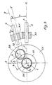
- Figures 1 and 1A show the case of an osteosynthesis intervention on the femur, Figure 1 showing the position of the device according to the invention, generally designated by the reference 1, when locating a transverse hole made in a spindle that is already assumed to be placed in the medullary canal of the femur.
- FIG. 1A shows an example of a spindle, also known, which can be used for an osteosynthesis intervention to which the apparatus according to the invention applies.
- this pin B is formed by a rod which is made of a metal inert to human moods and tissues.
- This rod is hollow and has a section approximately in the shape of a clover, giving it a certain flexibility so that the rod can adapt perfectly to the shape of the medullary canal when it is placed in the bone. It will therefore be noted from now on that not only does the rod not have a rectilinear shape, but that, moreover, during its positioning in the bone, it will admit a certain deformation which is not known a priori.
- Pin B has a proximal end which has a mouthpiece 1 which is internally threaded. When inserted, this proximal end first receives an anvil which is screwed into the threaded hole and on which the practitioner can strike to facilitate insertion.
- the spindle B has two transverse holes t1 and t2 which are intended to receive locking screws (not shown in the figures) which are generally delivered with the spindle B.
- pins are supplied in different length and diameter dimensions as is well known to specialists.
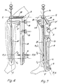
- Figures 2 and 2A show the case of an osteosynthesis intervention on the tibia, Figure 2A showing the shape of a pin B 'used in this case.
- this pin has a curved proximal end with a mouthpiece as in the case of the pin intended for the femur.
- this pin B ' has a through hole which is not visible in the drawing.
- pins B and B ' are identical in shape.
- the holes t1 and t2 which it is a question of locating do not retain, with respect to the mouthpiece, neither the axial position, nor the position in the radial plane with respect to the mouthpiece, which Obviously complicates the locating operation, it being understood that after insertion the holes are no longer visible and that it is desired to avoid any use of X-rays to locate them.
- FIG. 3 represents the operating principle of the apparatus according to the invention, the representation applying equally to the interventions of FIGS. 1 and 2 and of course to the other interventions which can be carried out by osteosynthesis.
- This figure schematically represents the bone bone surrounded by the CH flesh and provided with a medullary canal C.
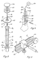
- Figure 4 we will already refer to Figure 4 to know the different main organs of the device according to the invention which, as can be seen, is used here for the containment of the fracture a femur bone.
- a pin B with its proximal end a and its distal end a2, the two transverse holes t1 and t2 as well as the mouthpiece 1 provided with its internal thread. It is on this mouth that is screwed a support 2 which constitutes the organ of the device remaining fixed during the location.
- This support which, in the embodiment shown, has the shape of a sector of a circle, defines a plane XOZ (here vertical) in which is located a point 0 considered as the origin of the coordinate system XYZ and which is a reference system in the description which follows.
- the origin O of this coordinate system is located on the axis OY constituting at this point the tangent to the axis of pin B which, as already indicated above, is not a straight line, but a line more or less curved, depending on the shape of the pin at the origin and also according to the deformations that this pin undergoes when it is inserted into the bone.
- the device also includes an adjustment bracket 3 which is articulated on the support 2 around the axis OY.
- the bracket 3 comprises a first branch 3a extending perpendicular to the axis OY as well as a second branch 3b which extends parallel to this axis along the pin B when the device is in place for the measurement.
- a slide 4 On the branch 3b is mounted movable along its longitudinal axis a slide 4 provided with two transverse passages 5 intended to receive a drilling guide 6.
- the latter is dimensioned to be able to receive a drilling drill 7 adaptable to a 'surgical drill (not shown).
- the slide 4 can move in a longitudinal slide 8 of the branch 3b while being able to be locked in this slide by a clamping mechanism (not shown) which can be actuated using a lever 9.
- the bracket 3 which is therefore articulated around the axis OY on the support 2 can be blocked relative to the latter by means of a screw 10 which acts on the circular edge 11 of the support 2 (see also FIGS. 5A and 5B which we will come back to later).
- the branch 3b is made in the form of a toggle and is therefore divided itself into a first part 12a close to the arm 3a as well as a part 12b in which is provided the slide 8, the articulation of the toggle (UU axis) can be locked with a screw 13.
- the apparatus also includes first feeler means 14 essentially formed by a rod 15 which can be inserted into the bore of spindle B and which carries at its front end a feeler 16 (FIG. 8) and at its opposite end an actuator 17, these members being described below with reference to FIG. 8.
- first feeler means 14 are provided with an index 18 which is intended to cooperate with a reference 19 provided on the bracket 3 and more precisely on the branch 3a thereof on the face which is not visible in FIG. 4.
- this mark 19 can be seen for example in FIGS. 5, 7 and 11, the index 18 being in turn the best visible in Figure 5.
- FIG. 9 represents an example of second feeler means 20 also intended to be inserted in the spindle B and acting in cooperation with the drilling guide 6.
- the purpose of the locating operation ultimately consists in placing the axis SS of the drilling guide (which is initially effectively coincident with the axis OX as shown) on the axis defined by the hole TB of the spindle, that is to say in coincidence with the RR axis. If this operation can be carried out with precision, the surgeon will be sure to pierce the bone in such a way that the drill passes in the spindle through the hole TB and this without it being necessary for him to actually see this hole. It will therefore not be necessary to carry out a bloody opening of the CH flesh at the place where the hole TB is located or to carry out any search by X-rays.
- the marking is carried out according to the invention in two stages which consist respectively and first of all in placing the drilling guide 6 so that its axis SS is located in a plane parallel to the axis RR and containing the axis OV, then shifting the drilling guide 6 in translation, so that the axes RR and SS coincide. It is understood, by examining FIG.
- the first step is carried out by rotating the bracket 3 around the axis 0-Y (first degree of freedom of the drilling guide), the second step consisting in breaking the toggle joint 12a , 12b at the location of the axis UU (second degree of freedom), the slight defect introduced by the fact that this last step is a rotation being negligible, taking into account the various dimensions of the organs in play (length of the spindle in particular ).
- the angular offset a is measured using the first feeler means 14 which define a plane in which the axis of the rod 15 and the index 18 are located (see FIGS. 4 and 5).
- the probe 16 is capable of making this plane coincide with the real axis R-R of the hole TB when it is inserted in the spindle B up to the height of the hole. If this axis is deviated, the index 18 will not be located in the plane XOY of FIG. 4, but will be inclined by the angle a sought with respect to the reference 19 traced on the branch 3a of the bracket 3.
- the first sensor means 14 have then done their work and the practitioner can remove them from pin B.
- these means comprise a flash lamp 21 fixed to the end of a catheter 22 which can be inserted into the pin B and which can be supplied with energy by a supply device 23 known per se connected to the lamp 21 by conductors 24.
- the flash lamp 21 is preferably associated with a reticle 25 which can be inserted in the block slide 4 (figure 4) in place of the drilling guide 6.
- the support 2 (FIG. 5) comprises a fixing plate 26 on which is formed a projection 26a which has a shape complementary to the mouth a1 of the pin B, this shape not being of revolution so that this plate can only be locked by simple screwing in one radial position relative to spindle B.
- the plate 26 is secured to a support plate 26b, for example using a dovetail attachment 27 , the circular edge of this support plate having two lateral flanges 28a and 28b delimiting a groove the bottom of which is hollowed out in a rounded shape (see FIG. 5B at 29).
- the plate 26 is pierced with a hole which is intended to receive the intermediate surface 30 of a screw 31, one of the ends 32 of which consists of a threaded end fitting suitable for the thread of the spindle B and the opposite end part of which 33 serves as a rotation bearing for the branch 3a of the bracket 3 by being inserted into an opening 34 of this branch.
- the screw 31 is pierced with an axial hole 35 in order to allow passage to the feeler means 15 and 20.
- the end face of the part 33 of the screw 31 is hollowed out with a hexagonal cavity 36 to allow screwing in. using a hexagon wrench.
- the locking screw 10 (FIG. 5A) which crosses the branch 3b through a threaded hole 37 carries at its end a centering finger 38 which is intended to come to bear against the bottom 29 of the groove delimited by the flanges 28a and 28b in order to apply the bracket 3 against the plate 26.
- This blocking also secures the rotation in rotation of the bracket relative to this plate and therefore maintains the consistency of the various organs of the device while making its disassembly extremely easy.
- the first probe means 14 have been shown in detail in FIG. 8 in which the rod 15, the probe 16 and the index 18 already mentioned above can be seen.
- the rod 15 carries two jaws 39a and 39b articulated around an axis 40 and biased towards the outside by means of a rope 41.
- the latter passes through the rod 15 and is attached to an actuation plate 42 sliding on the rod 15 against the action of a compression spring 43.
- This spring bears on a counter-plate 44 mounted transversely at the end of the rod 15 and fixed relative thereto.
- the jaws When the jaws reach the height of a hole t1 or t2, which the practitioner can be easily seen because the length of the spindle is known in advance, it releases the plate 42 and the jaws are introduced by their rounded ends into the corresponding hole in the spindle, which blocks the rod 15, not only in the direction of the length, but also in rotation, the jaws apart 39a and 39b defining a diametrical plane in which is located the axis of the hole concerned.
- a support plate 45 is slidably mounted on the rod 15, while being provided with springs 47 which cooperate with transverse grooves 48 provided on this rod to define different lengths, each position corresponding to a spindle length capable of being used by the surgeon. Consequently, at the start, this plate 45 is adjusted in such a way that the feeler means 14 are adapted to the length of the spindle B used. The streaks 48 are therefore advantageously associated with a length graduation.
- the support plate 45 carries the index 18 here constituted by a rectilinear rod extending radially. It is this rod which must therefore be placed in coincidence with the reference 19 of the branch 3a.
- the radial position of the index 18 corresponds to the plane defined by the jaws 39a and 39b apart, so that when these are blocked in a hole in the spindle, the index 18 is located in a plane in which is also the axis of the hole concerned.
- Figures 6 and 7 show the case of a location during an intervention on the tibia.
- the support of the device used in this case is slightly different from that just described.
- this support indicated by the reference 2 ′ comprises a lateral tab 49 in which the fixing screw 31 is inserted (FIG. 5) this support comprising a through hole to allow the insertion of the feeler means 14, roughly in the alignment of spindle B ', this support defining, as in the case described above, the reference plane YOZ with respect to which the other tracking parameters are defined.
- the apparatus of FIGS. 6 and 7 is identical to that shown in FIG. 4.
- this part 12b includes a rule 50 with an L-shaped section, the two wings of which are provided with grooves 51 and 52 in which a slide 53 is guided so as to be able to receive the drilling guide 6.
- the rule 50 can be blocked relative to the other part 12a of the toggle joint by the nut 13.
- the part 12b of the toggle joint constituting the branch 3b of the bracket 3 here comprises an adjustment block 55 which passes in front of a control unit which is flush with the upper face thereof.
- a mark 56 traced on this block can cooperate with a graduation 57 provided directly on the ruler.
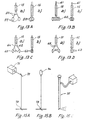
- FIGS. 13A to 13D show several possibilities for producing the first palpatory means.
- the rod 15 carries at its free end two elastic tabs 58 which are provided at their free end with balls 59 capable of partially penetrating the openings which define the transverse fixing holes in each pin.
- the tabs 58 and the balls 59 can be retracted by traction to enter roughly in the extension of the contour of the rod 15 during the insertion of the feeler means into the spindle.
- the diagrammatic view of FIG. 13B shows that the first feeler means can also include a bellows-shaped member 60 which can be inflated or deflated by blown air or discharged from a pipe 61 placed in the rod 15.
- FIG. 13C shows that it is also possible to provide at the end of the rod 15 two support tabs 62 carrying at their free end cups 63 biased at the spacing by a spring 64. These cups can be retracted as shown in b in FIG. 13C by axial traction on the legs 62, which compresses the spring 64.
- FIGS. 14A to 14D and 15A to 15C show several possible variants of the second feeler means.
- the feeler means 20 already shown in FIG. 9. It is therefore here a flash lamp 21 capable of emitting a luminous radiation 66 in the pin B towards the outside , this light radiation being apparent through the flesh of the limb being treated, the light effect being improved by the lightning provided by the lamp.
- FIG. 14B shows a variant in which a non-traumatic source of radiation 67 is provided outside the member under treatment, this source radiating through the hole concerned in pin B on a sensor 68 for this radiation, this can possibly be pulsed.
- the axis of the hole can be found for example by detecting a maximum amplitude of the radiation emitted.
- the radiation itself can be constituted by a high frequency radio wave of a wavelength chosen in such a way that it is not traumatic for the patient or for the treating staff.
- FIG. 14C it is a radiation transceiver 69 which sends its radiation to a reflector 70 placed opposite. This returns part of the radiation through the pin hole so that it can be detected there.
- FIG. 14D shows that in the case of a reflector 70 the radiation can be pulsed or otherwise characterized by a modulation in order to improve the detection thereof and, consequently, the accuracy of locating the pin hole .
- FIG. 15A shows yet another variant in which there is provided a light source 71 which can be a laser for example, emitting a light ray on a mirror 72 mounted in the support 3 of the apparatus and returning the light ray to another reflector device 73 located at the end of a rod (not shown).
- a light source 71 which can be a laser for example, emitting a light ray on a mirror 72 mounted in the support 3 of the apparatus and returning the light ray to another reflector device 73 located at the end of a rod (not shown).
- This latter device returns the radiation in both directions through the hole in the spindle, which allows it to be identified, for example by a reticle, as has been described in connection with FIG. 9.
- the laser 71 can be replaced by a light source with flashes 74 shown in FIG. 15B.
- a conventional endoscope 75 of the form shown in FIG. 15C it is also possible to use a conventional endoscope 75 of the form shown in FIG. 15C.
Claims (17)
gekennzeichnet dadurch, dass das Gerät ferner umfasst:
Applications Claiming Priority (4)
| Application Number | Priority Date | Filing Date | Title |
|---|---|---|---|
| FR8419956 | 1984-12-26 | ||
| FR8419956A FR2587196B1 (fr) | 1984-12-26 | 1984-12-26 | Appareil pour reperer in situ les trous transversaux d'une broche creuse implantee dans le canal medullaire, pour la contention des fragments d'un os fracture |
| FR8500881 | 1985-01-16 | ||
| FR8500881A FR2575918B1 (fr) | 1985-01-16 | 1985-01-16 | Appareil pour reperer in situ les trous transversaux d'une broche creuse implantee dans le canal medullaire, pour la contention des fragments d'un os fracture |
Publications (2)
| Publication Number | Publication Date |
|---|---|
| EP0187283A1 EP0187283A1 (de) | 1986-07-16 |
| EP0187283B1 true EP0187283B1 (de) | 1989-04-26 |
Family
ID=26224305
Family Applications (1)
| Application Number | Title | Priority Date | Filing Date |
|---|---|---|---|
| EP85115629A Expired EP0187283B1 (de) | 1984-12-26 | 1985-12-09 | Vorrichtung zum Auffinden in situ der Querbohrungen eines im Markkanal implantierten hohlen Stiftes für das Zusammenhalten der Fragmente eines gebrochenen Knochens |
Country Status (3)
| Country | Link |
|---|---|
| US (1) | US4865025A (de) |
| EP (1) | EP0187283B1 (de) |
| DE (1) | DE3569666D1 (de) |
Families Citing this family (85)
| Publication number | Priority date | Publication date | Assignee | Title |
|---|---|---|---|---|
| US4969889A (en) * | 1986-12-22 | 1990-11-13 | Zimmer, Inc. | Instrument for locating a hole |
| ATE85202T1 (de) * | 1987-10-21 | 1993-02-15 | Smith & Nephew Richards Inc | Chirurgisches instrument. |
| US5176681A (en) * | 1987-12-14 | 1993-01-05 | Howmedica International Inc. | Intramedullary intertrochanteric fracture fixation appliance and fitting device |
| US5122146A (en) * | 1988-02-04 | 1992-06-16 | Pfizer Hospital Products Group, Inc. | Apparatus for reducing a fracture |
| FR2634641A1 (fr) * | 1988-07-28 | 1990-02-02 | Michel Jean Pierre | Dispositif de visee pour le positionnement d'au moins un organe de fixation a travers un implant, du type clou centro-medullaire |
| US4881535A (en) * | 1988-09-06 | 1989-11-21 | Sohngen Gary W | Intramedullary rod targeting device |
| US5192321A (en) * | 1989-03-29 | 1993-03-09 | Andrew Strokon | Apparatus and method for knee surgery |
| FR2647006B1 (fr) * | 1989-05-22 | 1996-02-23 | Zimmer Sa | Dispositifs pour le montage d'un clou de renforcement et procede mettant en oeuvre ces dispositifs |
| US5049151A (en) * | 1989-12-20 | 1991-09-17 | Durham Alfred A | Magnetic positioner arrangement for locking screws for orthopedic hardward |
| DE9101037U1 (de) * | 1991-01-30 | 1991-04-18 | Howmedica Gmbh, 2314 Schoenkirchen, De | |
| US5207753A (en) * | 1991-02-18 | 1993-05-04 | Kannivelu Badrinath | Bone fracture repair apparatus and method |
| CA2073266A1 (en) * | 1991-07-09 | 1993-01-10 | Mehmet Rona | Distal targeting system |
| DE4141153A1 (de) * | 1991-12-13 | 1993-06-17 | Pennig Dietmar | Fuehrungsvorrichtung zum einbringen einer schenkelhalsschraube |
| US5207682A (en) * | 1992-02-04 | 1993-05-04 | Cripe Philip H | Adjustable drill guide |
| DE9202174U1 (de) * | 1992-02-13 | 1992-06-11 | Pennig, Dietmar, Dr.Med. Priv. Doz., 4400 Muenster, De | |
| US5681318A (en) * | 1992-02-13 | 1997-10-28 | Orthofix S.R.L. | Medullary cavity template |
| US5234434A (en) * | 1992-08-17 | 1993-08-10 | Marlowe Goble E | Mutliple guide sleeve drill guide |
| US5312411A (en) * | 1992-10-27 | 1994-05-17 | Smith & Nephew Richards, Inc. | Uni-compartmental femoral knee instruments and prosthesis |
| US5429640A (en) * | 1992-11-27 | 1995-07-04 | Clemson University | Intramedullary rod for fracture fixation of femoral shaft independent of ipsilateral femoral neck fracture fixation |
| FR2706279B1 (fr) * | 1993-06-18 | 1995-09-01 | Duhautois Bruno | Dispositif orthopédique ancillaire. |
| EP0637434A1 (de) * | 1993-07-08 | 1995-02-08 | SMITH & NEPHEW RICHARDS, INC. | Bohrlehre für externe Fixierung |
| US5417688A (en) * | 1993-12-22 | 1995-05-23 | Elstrom; John A. | Optical distal targeting system for an intramedullary nail |
| US5514145A (en) * | 1994-05-04 | 1996-05-07 | Durham; Alfred A. | Magnetic positioner arrangement for locking screws for orthopedic hardware |
| US5693054A (en) * | 1994-05-04 | 1997-12-02 | Durham; Alfred A. | Device and method for reducing fractures in long bones |
| JP3441513B2 (ja) * | 1994-05-20 | 2003-09-02 | ペンタックス株式会社 | 髄内釘用取り付け治具 |
| US5766174A (en) * | 1995-09-26 | 1998-06-16 | Orthologic Corporation | Intramedullary bone fixation device |
| US5833693A (en) * | 1997-05-02 | 1998-11-10 | Abrahami; Israel | Drill guide |
| US6036696A (en) * | 1997-12-19 | 2000-03-14 | Stryker Technologies Corporation | Guide-pin placement device and method of use |
| DE19819168C1 (de) * | 1998-04-24 | 2000-01-20 | Aap Implantate Ag | Zielgerät zur röntgenfreien proximalen und distalen Verriegelung von Marknägeln |
| US6129729A (en) * | 1998-11-11 | 2000-10-10 | Snyder; Samuel J. | Apparatus and method for targeting and/or installing fasteners into an intramedullary nail |
| US6379364B1 (en) | 2000-04-28 | 2002-04-30 | Synthes (Usa) | Dual drill guide for a locking bone plate |
| US6342057B1 (en) | 2000-04-28 | 2002-01-29 | Synthes (Usa) | Remotely aligned surgical drill guide |
| US6656189B1 (en) | 2000-05-25 | 2003-12-02 | Synthes (Usa) | Radiolucent aiming guide |
| AU8926301A (en) * | 2000-11-13 | 2002-05-16 | Benoist Girard Sas | Targeting apparatus for use in resectioning a femur when performing transfemoral osteotomy |
| AU780576B2 (en) | 2000-11-13 | 2005-04-07 | Stryker Ireland Limited | Targeting apparatus for use in performing transfemoral osteotomy |
| EP1205150B1 (de) | 2000-11-13 | 2007-04-04 | Benoist Girard Sas | Zielgerät zur endofemoralen Osteotomie |
| US7578825B2 (en) | 2004-04-19 | 2009-08-25 | Acumed Llc | Placement of fasteners into bone |
| US7090676B2 (en) | 2002-11-19 | 2006-08-15 | Acumed Llc | Adjustable bone plates |
| ATE489904T1 (de) * | 2001-06-27 | 2010-12-15 | Depuy Products Inc | Minimalinvasives orthopädisches gerät |
| US7618421B2 (en) * | 2001-10-10 | 2009-11-17 | Howmedica Osteonics Corp. | Tools for femoral resection in knee surgery |
| US7056322B2 (en) * | 2002-03-28 | 2006-06-06 | Depuy Orthopaedics, Inc. | Bone fastener targeting and compression/distraction device for an intramedullary nail and method of use |
| GB0209719D0 (en) * | 2002-04-27 | 2002-06-05 | Grampian Univ Hospitals | Apparatus and method |
| US20030229352A1 (en) | 2002-06-10 | 2003-12-11 | Penenberg Brad L. | Apparatus for and method of providing a hip replacement |
| US6997928B1 (en) | 2002-06-10 | 2006-02-14 | Wright Medical Technology, Inc. | Apparatus for and method of providing a hip replacement |
| US7651501B2 (en) | 2004-03-05 | 2010-01-26 | Wright Medical Technology, Inc. | Instrument for use in minimally invasive hip surgery |
| DE20211806U1 (de) * | 2002-08-01 | 2002-10-17 | Stryker Trauma Gmbh | Zielgerät für einen Verriegelungsnagel |
| AU2003294342A1 (en) * | 2002-11-19 | 2004-06-15 | Acumed Llc | Guide system for bone-repair devices |
| US6932818B2 (en) * | 2003-10-30 | 2005-08-23 | Alfred F. Behrens | Intramedullary nail-based bone fracture treatment |
| US7572282B2 (en) * | 2004-04-23 | 2009-08-11 | Depuy Spine Sarl | Spinal fixation plates and plate extensions |
| ITTO20040292A1 (it) | 2004-05-06 | 2004-08-06 | Ezio Visentin | Organo di collegamento atto ad essere introdotto all'interno di una struttura ossea di un corpo umano o animale e sistema per il rilevamento di almeno un punto di riferimento prestabilito nell'organo di collegamento stesso. |
| US7481815B2 (en) | 2004-09-23 | 2009-01-27 | Synthes (U.S.A.) | Coplanar X-ray guided aiming arm for locking of intramedullary nails |
| US7892287B2 (en) | 2004-09-27 | 2011-02-22 | Depuy Products, Inc. | Glenoid augment and associated method |
| US7922769B2 (en) * | 2004-09-27 | 2011-04-12 | Depuy Products, Inc. | Modular glenoid prosthesis and associated method |
| US7927335B2 (en) | 2004-09-27 | 2011-04-19 | Depuy Products, Inc. | Instrument for preparing an implant support surface and associated method |
| US20060074353A1 (en) * | 2004-09-27 | 2006-04-06 | Deffenbaugh Daren L | Glenoid instrumentation and associated method |
| AU2006216759B2 (en) * | 2005-02-22 | 2011-11-17 | Smith & Nephew, Inc. | Instrument for targeting blocking screws |
| EP1861021A1 (de) * | 2005-03-17 | 2007-12-05 | Smith and Nephew, Inc. | Positionierungssystem für ein medizinisches befestigungselement |
| US20070005065A1 (en) * | 2005-06-17 | 2007-01-04 | Fernandez Dell Oca Alberto A | Aiming arm hole shaped to perform an incision through, and method to use that same |
| EP1759643A1 (de) * | 2005-08-30 | 2007-03-07 | Orthofix International B.V. | Zielgerät für Verriegelungsnägel |
| US9192398B2 (en) * | 2005-09-19 | 2015-11-24 | DePuy Synthes Products, Inc. | Orthopedic implant insertion handle and aiming guide |
| EP2081506B1 (de) * | 2006-06-29 | 2010-09-08 | L.r.s. Ortho Ltd. | System zur lokalisation von distalen löchern eines marknagels |
| US8685034B2 (en) * | 2006-08-10 | 2014-04-01 | Stryker Trauma Gmbh | Distal targeting device |
| US20100030219A1 (en) * | 2007-07-01 | 2010-02-04 | L.R.S. Ortho Ltd. | Orthopedic navigation system and method |
| WO2009109371A2 (en) * | 2008-03-04 | 2009-09-11 | Sector 6 Technologies S.A. | Device for targeting locking holes in intramedullary nails |
| US20090299375A1 (en) * | 2008-06-03 | 2009-12-03 | Zimmer, Inc. | Catheter nail targeting guide |
| US8241365B2 (en) * | 2008-12-23 | 2012-08-14 | Depuy Products, Inc. | Shoulder prosthesis with vault-filling structure having bone-sparing configuration |
| EP2493398B1 (de) | 2009-10-28 | 2015-12-16 | Chirmat Sàrl | Vorrichtung zur positionierung und einstellung einer sichtachse |
| US8231683B2 (en) | 2009-12-08 | 2012-07-31 | Depuy Products, Inc. | Shoulder prosthesis assembly having glenoid rim replacement structure |
| US8480750B2 (en) | 2010-11-24 | 2013-07-09 | DePuy Synthes Products, LLC | Modular glenoid prosthesis |
| US8465548B2 (en) | 2010-11-24 | 2013-06-18 | DePuy Synthes Products, LLC | Modular glenoid prosthesis |
| EP2713908B1 (de) | 2011-05-25 | 2015-04-22 | Synthes GmbH | Zielvorrichtung mit röntgendichten markern |
| JP2014522270A (ja) * | 2011-05-25 | 2014-09-04 | シンセス・ゲーエムベーハー | 調節可能な照準組立体 |
| BR112014003571B1 (pt) * | 2011-08-15 | 2021-03-09 | Orthofix S.R.L. | montagem de alvejamento para um sistema de prego de compressão |
| US8551106B2 (en) * | 2011-09-30 | 2013-10-08 | Arthrocare Corporation | Method and apparatus for installation of intramedullary medical device |
| US8968324B2 (en) * | 2011-10-27 | 2015-03-03 | Kettering University | Adjustable jig and method for targeting interlocking holes of an intramedullary nail |
| CN104159532B (zh) | 2011-12-29 | 2017-05-10 | 新特斯有限责任公司 | 髌上插入系统、套件和方法 |
| US9295488B2 (en) * | 2012-08-09 | 2016-03-29 | Wilson T. Asfora | Joint fusion |
| WO2014194965A1 (en) | 2013-06-07 | 2014-12-11 | Stryker Trauma Gmbh | Targeting adjustment system for an intramedullary nail |
| KR102355067B1 (ko) * | 2013-12-05 | 2022-01-24 | 조나단 파이벨 | 뼈의 융합, 안정화 및/또는 고정을 위한 시스템, 방법 및 장치와 함께 사용하기 위한 타겟팅 디바이스 |
| TWI678184B (zh) * | 2014-04-25 | 2019-12-01 | 德派信迪思產品公司 | 瞄準裝置系統 |
| US10201358B2 (en) | 2015-04-21 | 2019-02-12 | Acumed Llc | Articulating syndesmosis targeting guide device and method |
| US10213219B2 (en) * | 2015-06-16 | 2019-02-26 | Arthrex, Inc. | Targeting guide assembly |
| GB2544501B (en) * | 2015-11-18 | 2017-12-13 | Grampian Health Board | Variable curve jig for an intramedullary nail |
| CA3013887A1 (en) * | 2016-02-19 | 2017-08-24 | Sunnybrook Research Institute | Positioning and alignment instrument for introducing surgical devices into bone |
| WO2023081339A1 (en) | 2021-11-05 | 2023-05-11 | Bauer Jordan Andre | Design and method for proximal and distal screw fixation in intramedullary tibial nails |
Family Cites Families (21)
| Publication number | Priority date | Publication date | Assignee | Title |
|---|---|---|---|---|
| US2666430A (en) * | 1949-05-31 | 1954-01-19 | Gispert Humberto Altamirano | Hip nail aiming and guiding device |
| US2697433A (en) * | 1951-12-04 | 1954-12-21 | Max A Zehnder | Device for accurately positioning and guiding guide wires used in the nailing of thefemoral neck |
| US3670724A (en) * | 1970-03-12 | 1972-06-20 | David N Bosacco | Prosthetic or fracture device and method |
| US3674008A (en) * | 1970-07-13 | 1972-07-04 | Battelle Development Corp | Quantitative pulsed transilluminator and method of operation |
| US3814089A (en) * | 1971-09-24 | 1974-06-04 | W Deyerle | Drill jig for total hip prosthesis |
| US4033043A (en) * | 1975-07-09 | 1977-07-05 | Cunningham Frank W | Gauge for measuring length of an opening |
| NL173019C (nl) * | 1977-04-01 | 1983-12-01 | Atlantis Sa | Samenstel voor het inwendig spalken van een gebroken pijpbot. |
| DE7805301U1 (de) * | 1978-02-22 | 1978-07-06 | Howmedica International, Inc. Zweigniederlassung Kiel, 2300 Kiel | Distales Zielgerät für die Verriegeliingsnagelung |
| CH633954A5 (de) * | 1978-05-20 | 1983-01-14 | Synthes Ag | Einrichtung zum einschrauben einer schraube in einen knochen bei einer operativen knochenbehandlung. |
| SU825047A1 (ru) * | 1979-05-31 | 1981-04-30 | Chernovits G Med Inst | Направляющее устройство для введения штифта в фиксатор 1 |
| SU992045A1 (ru) * | 1981-06-24 | 1983-01-30 | Тюменский государственный медицинский институт | Устройство дл интрамедулл рного остеосинтеза |
| ES8302447A1 (es) * | 1981-12-11 | 1983-01-16 | Pichel Moure Carlos | Osteoscopio para realizar el enclavado de las fracturas a cielo cerrado, mediante control endoscopio . |
| US4476870A (en) * | 1982-03-30 | 1984-10-16 | The United States Of America As Represented By The Department Of Health And Human Services | Fiber optic PO.sbsb.2 probe |
| DE8208970U1 (de) * | 1982-03-30 | 1982-09-09 | Howmedica International, Inc. Zweigniederlassung Kiel, 2301 Schönkirchen | Distales Zielgerät für einen Verriegelungsnagel |
| US4519100A (en) * | 1982-09-30 | 1985-05-28 | Orthopedic Equipment Co. Inc. | Distal locking intramedullary nail |
| US4600011A (en) * | 1982-11-03 | 1986-07-15 | The University Court Of The University Of Aberdeen | Tele-diaphanography apparatus |
| US4567882A (en) * | 1982-12-06 | 1986-02-04 | Vanderbilt University | Method for locating the illuminated tip of an endotracheal tube |
| DE3332642A1 (de) * | 1983-09-09 | 1985-04-04 | Ortopedia Gmbh, 2300 Kiel | Vorrichtung zum auffinden von querbohrungen intramedullaerer implantate |
| US4611586A (en) * | 1983-10-06 | 1986-09-16 | John M. Agee | Articulated Colles' fracture splint |
| US4644943A (en) * | 1984-07-20 | 1987-02-24 | Regents Of The University Of Minnesota | Bone fixation device |
| US4667664A (en) * | 1985-01-18 | 1987-05-26 | Richards Medical Company | Blind hole targeting device for orthopedic surgery |
-
1985
- 1985-12-09 EP EP85115629A patent/EP0187283B1/de not_active Expired
- 1985-12-09 DE DE8585115629T patent/DE3569666D1/de not_active Expired
-
1988
- 1988-07-25 US US07/224,286 patent/US4865025A/en not_active Expired - Fee Related
Also Published As
| Publication number | Publication date |
|---|---|
| US4865025A (en) | 1989-09-12 |
| EP0187283A1 (de) | 1986-07-16 |
| DE3569666D1 (en) | 1989-06-01 |
Similar Documents
| Publication | Publication Date | Title |
|---|---|---|
| EP0187283B1 (de) | Vorrichtung zum Auffinden in situ der Querbohrungen eines im Markkanal implantierten hohlen Stiftes für das Zusammenhalten der Fragmente eines gebrochenen Knochens | |
| EP1563810B1 (de) | Chirurgische Vorrichtung zum Einsetzen einer Totalhüftprothese | |
| EP1189547B8 (de) | Vorrichtung zum begrenzen des eindringens eines bohrwerkzeugs in der zahnchirurgie, sowie vorrichtung zum kalibrieren und speichern der eindringtiefe | |
| JP3280631B2 (ja) | 整形外科学的ターゲティング装置、該装置用のアーム状装置及び角度案内体装置 | |
| ES2662643T3 (es) | Métodos y aparato para determinar la colocación de pasadores durante la cirugía de cadera | |
| KR100271589B1 (ko) | 절단안내기구 | |
| EP0408416A1 (de) | Chirurgisches Hilfsinstrument zur Lokalisierung und zum Bohren femoraler und tibialer Einführungstunnel für einen Knieligamentersatz | |
| FR2721195A1 (fr) | Dispositif de mise en place d'une lame-plaque pour la réalisation d'une ostéotomie de réaxation dans une zone osseuse. | |
| EP1341468A1 (de) | System zur bestimmung der position einer knieprothese | |
| CA2705556C (fr) | Objet-test pour le controle qualite d'un appareil de traitement par radiotherapie et procedes de fabrication et d'utilisation dudit objet-test | |
| US20120197263A1 (en) | Instrument Set for Screwing an Implant Into an Intervertebral Disc Space | |
| FR2906452A1 (fr) | Ancillaire de visee pour resurfacage de la tete femorale | |
| WO2010026339A1 (fr) | Ensemble d'ostéosynthèse et système chirurgical pour pratiquer l'ostéosynthèse comprenant un tel ensemble | |
| FR2587196A1 (fr) | Appareil pour reperer in situ les trous transversaux d'une broche creuse implantee dans le canal medullaire, pour la contention des fragments d'un os fracture | |
| HU225838B1 (en) | An appliance for the determination of the position of medullary cavity nail bores | |
| WO2010023399A1 (fr) | Ensemble d'ancillaires pour implanter une prothese de genou | |
| FR2575918A1 (fr) | Appareil pour reperer in situ les trous transversaux d'une broche creuse implantee dans le canal medullaire, pour la contention des fragments d'un os fracture | |
| FR2770763A1 (fr) | Dispositif pour positionner un patient sur un support reglable | |
| EP0919200A1 (de) | Osteosynthesesystem für den Schenkelhalsbereich des Femurs | |
| FR2882250A1 (fr) | Dispositifs de guidage et de coupe pour la preparation de sites osseux en chirurgie implantaire | |
| EP0868886A1 (de) | Verfahren und Vorrichtung zur Markierung und Ortung einer Behandlungszone in einem Organismus | |
| FR2559376A1 (fr) | Dispositif de visee des orifices de verrouillage de clous chirurgicaux | |
| FR2801185A1 (fr) | Video endoscope securise a profilometre laser integre pour la chirurgie assistee par ordinateur | |
| FR3034004A1 (fr) | Systeme de guidage pour la mise en oeuvre d'une osteotomie | |
| EP2572658A1 (de) | Chirurgenbesteck für die Durchführung der Arthrodese des Knöchels, sowie entsprechendes Knöchelarthrodese-Kit |
Legal Events
| Date | Code | Title | Description |
|---|---|---|---|
| PUAI | Public reference made under article 153(3) epc to a published international application that has entered the european phase |
Free format text: ORIGINAL CODE: 0009012 |
|
| AK | Designated contracting states |
Kind code of ref document: A1 Designated state(s): CH DE FR GB IT LI |
|
| 17P | Request for examination filed |
Effective date: 19860827 |
|
| 17Q | First examination report despatched |
Effective date: 19880226 |
|
| GRAA | (expected) grant |
Free format text: ORIGINAL CODE: 0009210 |
|
| AK | Designated contracting states |
Kind code of ref document: B1 Designated state(s): CH DE FR GB IT LI |
|
| PG25 | Lapsed in a contracting state [announced via postgrant information from national office to epo] |
Ref country code: IT Free format text: LAPSE BECAUSE OF FAILURE TO SUBMIT A TRANSLATION OF THE DESCRIPTION OR TO PAY THE FEE WITHIN THE PRESCRIBED TIME-LIMIT;WARNING: LAPSES OF ITALIAN PATENTS WITH EFFECTIVE DATE BEFORE 2007 MAY HAVE OCCURRED AT ANY TIME BEFORE 2007. THE CORRECT EFFECTIVE DATE MAY BE DIFFERENT FROM THE ONE RECORDED. Effective date: 19890426 Ref country code: GB Effective date: 19890426 |
|
| REF | Corresponds to: |
Ref document number: 3569666 Country of ref document: DE Date of ref document: 19890601 |
|
| GBV | Gb: ep patent (uk) treated as always having been void in accordance with gb section 77(7)/1977 [no translation filed] | ||
| PG25 | Lapsed in a contracting state [announced via postgrant information from national office to epo] |
Ref country code: LI Effective date: 19891231 Ref country code: CH Effective date: 19891231 |
|
| PLBE | No opposition filed within time limit |
Free format text: ORIGINAL CODE: 0009261 |
|
| STAA | Information on the status of an ep patent application or granted ep patent |
Free format text: STATUS: NO OPPOSITION FILED WITHIN TIME LIMIT |
|
| 26N | No opposition filed | ||
| PG25 | Lapsed in a contracting state [announced via postgrant information from national office to epo] |
Ref country code: FR Effective date: 19900831 |
|
| REG | Reference to a national code |
Ref country code: CH Ref legal event code: PL |
|
| PG25 | Lapsed in a contracting state [announced via postgrant information from national office to epo] |
Ref country code: DE Effective date: 19900901 |
|
| REG | Reference to a national code |
Ref country code: FR Ref legal event code: ST |