EP2755580B1 - Marknagel verriegelungslochanordnung - Google Patents
Marknagel verriegelungslochanordnung Download PDFInfo
- Publication number
- EP2755580B1 EP2755580B1 EP11761010.5A EP11761010A EP2755580B1 EP 2755580 B1 EP2755580 B1 EP 2755580B1 EP 11761010 A EP11761010 A EP 11761010A EP 2755580 B1 EP2755580 B1 EP 2755580B1
- Authority
- EP
- European Patent Office
- Prior art keywords
- hole
- intramedullary nail
- orientation
- driving end
- transponder
- Prior art date
- Legal status (The legal status is an assumption and is not a legal conclusion. Google has not performed a legal analysis and makes no representation as to the accuracy of the status listed.)
- Active
Links
- 230000008685 targeting Effects 0.000 claims description 25
- 230000005855 radiation Effects 0.000 claims description 19
- 230000008878 coupling Effects 0.000 claims description 5
- 238000010168 coupling process Methods 0.000 claims description 5
- 238000005859 coupling reaction Methods 0.000 claims description 5
- 230000011664 signaling Effects 0.000 claims description 2
- 238000005553 drilling Methods 0.000 description 12
- 210000000988 bone and bone Anatomy 0.000 description 11
- 210000002303 tibia Anatomy 0.000 description 10
- 210000000689 upper leg Anatomy 0.000 description 10
- 210000002758 humerus Anatomy 0.000 description 7
- 238000004873 anchoring Methods 0.000 description 2
- 230000001419 dependent effect Effects 0.000 description 2
- 230000037431 insertion Effects 0.000 description 2
- 238000003780 insertion Methods 0.000 description 2
- 206010002091 Anaesthesia Diseases 0.000 description 1
- 230000037005 anaesthesia Effects 0.000 description 1
- 238000001949 anaesthesia Methods 0.000 description 1
- 230000009286 beneficial effect Effects 0.000 description 1
- 239000012634 fragment Substances 0.000 description 1
- 238000002513 implantation Methods 0.000 description 1
- 210000001699 lower leg Anatomy 0.000 description 1
- 210000001519 tissue Anatomy 0.000 description 1
- 230000000007 visual effect Effects 0.000 description 1
Images


Classifications
-
- A—HUMAN NECESSITIES
- A61—MEDICAL OR VETERINARY SCIENCE; HYGIENE
- A61B—DIAGNOSIS; SURGERY; IDENTIFICATION
- A61B17/00—Surgical instruments, devices or methods, e.g. tourniquets
- A61B17/56—Surgical instruments or methods for treatment of bones or joints; Devices specially adapted therefor
- A61B17/58—Surgical instruments or methods for treatment of bones or joints; Devices specially adapted therefor for osteosynthesis, e.g. bone plates, screws, setting implements or the like
- A61B17/68—Internal fixation devices, including fasteners and spinal fixators, even if a part thereof projects from the skin
- A61B17/72—Intramedullary pins, nails or other devices
- A61B17/7233—Intramedullary pins, nails or other devices with special means of locking the nail to the bone
-
- A—HUMAN NECESSITIES
- A61—MEDICAL OR VETERINARY SCIENCE; HYGIENE
- A61B—DIAGNOSIS; SURGERY; IDENTIFICATION
- A61B17/00—Surgical instruments, devices or methods, e.g. tourniquets
- A61B17/16—Bone cutting, breaking or removal means other than saws, e.g. Osteoclasts; Drills or chisels for bones; Trepans
- A61B17/17—Guides or aligning means for drills, mills, pins or wires
- A61B17/1707—Guides or aligning means for drills, mills, pins or wires using electromagnetic effects, e.g. with magnet and external sensors
-
- A—HUMAN NECESSITIES
- A61—MEDICAL OR VETERINARY SCIENCE; HYGIENE
- A61B—DIAGNOSIS; SURGERY; IDENTIFICATION
- A61B17/00—Surgical instruments, devices or methods, e.g. tourniquets
- A61B17/16—Bone cutting, breaking or removal means other than saws, e.g. Osteoclasts; Drills or chisels for bones; Trepans
- A61B17/17—Guides or aligning means for drills, mills, pins or wires
- A61B17/1725—Guides or aligning means for drills, mills, pins or wires for applying transverse screws or pins through intramedullary nails or pins
-
- A—HUMAN NECESSITIES
- A61—MEDICAL OR VETERINARY SCIENCE; HYGIENE
- A61B—DIAGNOSIS; SURGERY; IDENTIFICATION
- A61B17/00—Surgical instruments, devices or methods, e.g. tourniquets
- A61B17/56—Surgical instruments or methods for treatment of bones or joints; Devices specially adapted therefor
- A61B17/58—Surgical instruments or methods for treatment of bones or joints; Devices specially adapted therefor for osteosynthesis, e.g. bone plates, screws, setting implements or the like
- A61B17/68—Internal fixation devices, including fasteners and spinal fixators, even if a part thereof projects from the skin
- A61B17/72—Intramedullary pins, nails or other devices
-
- A—HUMAN NECESSITIES
- A61—MEDICAL OR VETERINARY SCIENCE; HYGIENE
- A61B—DIAGNOSIS; SURGERY; IDENTIFICATION
- A61B90/00—Instruments, implements or accessories specially adapted for surgery or diagnosis and not covered by any of the groups A61B1/00 - A61B50/00, e.g. for luxation treatment or for protecting wound edges
- A61B90/39—Markers, e.g. radio-opaque or breast lesions markers
- A61B2090/397—Markers, e.g. radio-opaque or breast lesions markers electromagnetic other than visible, e.g. microwave
-
- A—HUMAN NECESSITIES
- A61—MEDICAL OR VETERINARY SCIENCE; HYGIENE
- A61B—DIAGNOSIS; SURGERY; IDENTIFICATION
- A61B5/00—Measuring for diagnostic purposes; Identification of persons
- A61B5/06—Devices, other than using radiation, for detecting or locating foreign bodies ; determining position of probes within or on the body of the patient
Definitions
- the invention generally relates to an intramedullary nail.
- the invention relates to a locking hole arrangement provided at a non-driving end portion of an intramedullary nail, wherein this end portion of the nail is adapted to be positioned at a distal end portion of a humerus or a tibia, or at a proximal or at a distal end portion of a femur.
- the proximal end of the bone is the end of the bone being oriented toward the heart of the human body.
- the distal end of the bone is the end of the bone being oriented away from the heart of the human body.
- An intramedullary nail may be a femur nail, a humerus nail or a tibia nail, wherein the intramedullary nail comprises a non-driving end and a driving end.
- the non-driving end is the end of the nail which firstly enters the intramedullary channel of a bone. Entering the bone from the proximal end of the bone is denoted as antegrade insertion. Entering the bone from the distal end of the bone is denoted as retrograde insertion.
- a nail adapted to be implanted from the proximal end of the tibia may be denoted as antegrade tibia nail
- a nail adapted to be implanted from the distal end of the femur may be denoted as retrograde femur nail
- a nail adapted to be implanted from the proximal end of the femur may be denoted as antegrade femur nail
- a nail adapted to be implanted from the proximal end of the humerus may be denoted as antegrade humerus nail.
- a different locking pattern of the non-driving end portion of an intramedullary nail exists for each one of different nails, e.g. humerus, tibia, femur nails. Locking of the non-driving end portion of an intramedullary nail is performed mostly freehand.
- US 6,547,791 B1 discloses a tibia nail for retrograde implantation, comprising a tube with a continuous longitudinal bore and including a first anchoring portion with several cross-bores at its non-driving end portion, an adjoining connecting portion, a shank and a second anchoring portion at its driving end portion.
- the arrangement of the cross-bores permits to fix several fragments at their positions in the region of the tibia plateau, i.e. at the proximal end portion of the tibia.
- WO 2010/028046 A1 discloses an intramedullary nail targeting device for detecting the precise location and position of an opening of a through bore in an intramedullary nail in a bone or similar object within a body of tissue.
- An intramedullary nail is described having three bores for receiving screws in the distal end section of the nail, with two bores having substantially the same orientation and the third hole being perpendicular thereto.
- all four openings have the same orientation.
- an intramedullary nail comprises a driving end portion and a non-driving end portion with a longitudinal axis.
- the non-driving end portion comprises a locking hole arrangement with four holes, i.e. a first hole, a second hole, a third hole, and a fourth hole.
- the four holes are arranged as a sequence from the non-driving end of the intramedullary nail in a direction to the driving end of the nail, with the first hole arranged closer to the non-driving end than the second hole, the second hole arranged closer to the non-driving end than the third hole, and the third hole arranged closer to the non-driving end than the fourth hole.
- the first hole and the fourth hole have a corresponding first orientation and the second hole and the third hole have a corresponding second orientation.
- the first orientation is a medio-lateral orientation and the second orientation is an anterior-posterior orientation.
- the medio-lateral orientation and the anterior-posterior orientation are substantially orthogonal with respect to each other.
- orthogonal may include in this context an angle between 80 and 100 degrees.
- orientation of the first and fourth holes of the locking hole arrangement at the non-driving end portion of the intramedullary nail may also be different to orthogonal relative to the orientation of the second and third holes, as long as this orientation is well defined and, thus, known.
- the orientation may be 60 degrees or may be 45 degrees.
- the first, second, third and fourth holes are respectively adapted for receiving a locking screw.
- Such an arrangement of locking holes may be particularly usable at a non-driving end portion of an antegrade humerus nail, an antegrade tibia nail, an antegrade femur nail as well as a retrograde femur nail.
- At least one of the first hole, the second hole, the third hole and the fourth hole is orthogonally oriented with respect to the longitudinal axis of the non-driving end portion.
- an orientation not orthogonally with respect to the longitudinal axis may be provided. It may be, that all holes are inclined in a same way relative to the longitudinal axis, but also that at least one hole is inclined in another way as the other ones.
- a distance between a centre axis of the first hole and the centre axis of the second hole corresponds to a distance between a centre axis of the third hole and a centre axis of the fourth hole.
- the distances from a non-driving end of the intramedullary nail to a respective centre axis of a hole may be as follows:
- a distance from the non-driving end to the centre axis of the second hole may be 9 to 49 mm, preferably 10 mm.
- a distance from the non-driving end to the centre axis of the third hole may be 24 to 64 mm, preferably 25 mm.
- a distance from the non-driving end to the centre axis of the fourth hole may be 29 to 69 mm, preferably 30 mm.
- the intramedullary nail comprises a fifth hole, wherein a transponder may be arranged in this fifth hole.
- the fifth hole may have the same orientation as the first hole and the fourth hole, and may be centred between the second hole and the third hole, as well as between the first hole and the fourth hole.
- the distance from the non-driving end of the intramedullary nail to the fifth hole may be 16.5 to 56.5 mm, preferably 17.5 mm.
- the five holes are equally spaced from each other.
- the transponder may be adapted for generating a signal with a first preferred radiation direction in which the signal has specific symmetry characteristics, allowing the determination of the orientation of the first preferred radiation direction.
- the signal symmetry characteristics may be the characteristics of a dipole.
- the first preferred direction may be the axis of the dipole.
- the dipole signal characteristics may be generated by a coil.
- the transponder may be adapted for generating a signal being indicative for determining at least one of a spatial position and spatial orientation of the transponder so as to allow determining a respective spatial position and spatial orientation of at least one of the first, second, third and fourth holes, based on a predetermined spatial position and spatial orientation of the respective hole with respect to the transponder.
- first preferred radiation direction may be aligned with the orientation, i.e. the centre axis of the fifth hole.
- a second preferred radiation direction may be orthogonal to the first preferred radiation direction.
- At least one of the first hole, the second hole, the third hole, the fourth hole and the fifth hole comprises a thread.
- a locking screw and alternatively a transponder may be reliably arranged and fixed within one of the holes.
- a combination of an intramedullary nail, as described above, with a targeting detector is provided, wherein the targeting detector is arranged to detect the signal generating by a transponder at the intramedullary nail.
- the targeting detector may further be arranged to detect the orientation of the transponder, wherein the detector is adapted for signalling the correspondence of the orientation of at least one of the first hole, the second hole, the third hole and the fourth hole on the one hand, and a targeting orientation on the other hand, based on a predetermined spatial position and a spatial orientation of the respective first hole, second hole, third hole and fourth hole with respect to the transponder.
- the targeting detector may be located at a tool for introducing a locking screw, helping a physician to localize the locking hole in the non-driving end portion of the intramedullary nail during a so-called freehand introduction of a locking screw.
- the targeting detector may be located at a targeting device having a coupling portion adapted to be coupled to the driving end portion of the intramedullary nail.
- the targeting device may further comprise a drilling gauge with a drilling axis, for easily introducing a locking screw into a respective locking hole in the non-driving end portion of the intramedullary nail.
- US 7,686,818 B2 relates to a locking nail and stereotaxic apparatus thereof. Furthermore, US 2008/0170473 A1 relates to a targeting system. These documents especially provide information concerning exemplary transponders and the use thereof.
- Fig. 1 is an isometric view of a non-driving end portion 20 of an intramedullary nail 1.
- the non-driving end portion 20 includes a longitudinal axis 21, a non-driving end 22 and a longitudinal bore 23 arranged substantially parallel to the longitudinal axis 21.
- the non-driving end 22 is formed as a blunt end of the intramedullary nail 1. Furthermore, five holes are illustrated in Fig. 1 .
- the intramedullary nail 1 comprises a first hole 31 with a centre axis 31a, a second hole 32 with a centre axis 32a, a fifth hole 35 with a centre axis 35a, a third hole 33 with a centre axis 33a, and a fourth hole 34 with a centre axis 34a.
- the first hole 31, the fifth hole 35 and the fourth hole 34 are orientated in a first orientation
- the second hole 32 and the third hole 33 are orientated in a second orientation.
- Each of the centre axes of the holes is oriented orthogonal to the longitudinal axis 21. Furthermore, the first hole 31 and the fourth hole 34 are orientated orthogonal to the second hole 32 and the third hole 33.
- the fifth hole 35 is arranged in the middle between the first and fourth holes, orientated in the same direction as the first and fourth holes. The fifth hole 35 is adapted for receiving a transponder. Additionally, in Fig. 1 the directions medio-lateral ML and anterior-posterior AP are illustrated.
- Fig. 2 is a side view of the intramedullary nail in the medio-lateral direction.
- a transponder 50 may be arranged in the fifth hole, in the middle between the first hole 31 and the fourth hole 34.
- the visual part of the transponder has a greater diameter than the respective diameter of the first and fourth holes.
- Fig. 2 Further illustrated in Fig. 2 are the distances between some of the centre axes of the holes.
- the distance between the centre axis of the first hole 31 and the centre axis of the fourth hole 34 is indicated as d1.
- the distance between the centre axis of the first hole 31 and the centre axis 32a of the second hole 32, as well as the distance between the centre axis 33a of the third hole 33 and the centre axis of the fourth hole 34 is indicated as d2, that is, the distance between the centre axes of the first and second holes is equal to that of the third and fourth holes.
- the distance between the centre axis of the fourth hole 34 and the centre axis of the fifth hole with the transponder 50 is indicated as d1/2, that is, the transponder is arranged in the middle between the first and fourth holes.
- a driving end portion 10 of the intramedullary nails 1 is illustrated in fig. 2 . It is noted that the driving end portion 10 may have any shape or size, depending as to whether the intramedullary nail 1 should be used as humerus nail, as tibia nail or as femur nail.
- Fig. 3 is a section view of the non-driving end portion 20 along the plane A-A of Fig. 2 .
- the intramedullary nail 1 has a hollow shaft (due to the longitudinal bore 23) with a longitudinal axis 21 at its non-driving end portion 20.
- the first, fourth and fifth hole are illustrated parallel to each other and in a first orientation, within the plane of the figure, and the second and third holes are illustrated parallel to each other and in a second orientation, perpendicular to the plane of the figure.
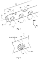
- Fig. 4 is an isometric view showing, in detail, one of the holes 31, 32, 33, 34 and 35 of the non-driving end portion of the intramedullary nail 1.
- the hole in fig. 4 includes a thread 38 and a chamfer 39.
- the chamfer 39 may facilitate an introduction of a screw or of a transponder into the hole.
- the thread 38 may be provided in only one of or at least one of as well as in every one of the holes in the non-driving end portion of the intramedullary nail.
- the holes may also comprise only a chamfer 39 and no thread 38.
- Fig. 5 is a detailed view of the fifth hole 35 with a transponder 50 located within the fifth hole. Additionally, a first preferred radiation direction 51 of the transponder 50 and a second preferred radiation direction 52 of the transponder 50 are illustrated.
- the first preferred radiation direction 51 is substantially aligned with the centre axis of the fifth hole 35 and thus with the centre axis of the transponder 50.
- the second preferred radiation direction 52 is orientated orthogonal to the first preferred radiation direction 51. It is noted that the second preferred radiation direction may be within a plane being orthogonal to the first preferred radiation direction.
- Fig. 6 shows a combination of an intramedullary nail 1 together with a targeting device 100, wherein the targeting device 100 includes a portion 110 with a coupling portion 112, wherein the coupling portion 112 may be adapted to be coupled to the driving end portion 10 of the intramedullary nail 1. Furthermore, the targeting device 100 comprises a portion 120 including at least one drilling gauge 130 with a drilling axis 130a.
- the targeting device 100 is dimensioned so that the drilling axis of one of the drilling gauges 130 is aligned with, for example, the centre axis 33a of the third hole 33, and that the drilling axis of another one of the drilling gauges 130 is aligned with the centre axis 32a of the second hole 32.
- the targeting device 100 may further comprise a targeting detector 150 arranged in a known relation to the holes of the non-driving end portion of the intramedullary nail, so that the targeting detector 150 may receive signals from the transponder 50 to be able to indicate the relative position of the respective drilling gauge relative to one of the holes of the locking hole arrangement in the non-driving end portion 20 of the intramedullary nail 1.
- the targeting device 100 may also be orientated relative to the intramedullary nail so that drilling gauges may be aligned with the first or the fourth hole in the intramedullary nail.
Claims (15)
- Marknagel, Folgendes umfassend:einen antriebsseitigen Abschnitt (10) undeinen gegenantriebsseitigen Abschnitt (20) mit einer Längsachse (21),wobei der gegenantriebsseitige Abschnitt eine Verriegelungslochanordnung mit einem ersten Loch (31), einem zweiten Loch (32), einem dritten Loch (33) und einem vierten Loch (34) umfasst,wobei das erste Loch am nächsten zu einer Gegenantriebsseite (22) des Marknagels angeordnet ist als das zweite Loch, das zweite Loch näher an der Gegenantriebsseite angeordnet ist als das dritte Loch und das dritte Loch näher an der Gegenantriebsseite angeordnet ist als das vierte Loch,wobei das erste Loch und das vierte Loch eine entsprechende erste Ausrichtung aufweisen, dadurch gekennzeichnet, dass das zweite Loch und das dritte Loch eine entsprechende zweite Ausrichtung aufweisen,wobei ein Abstand (d2) zwischen einer Mittelachse (31a) des ersten Lochs (31) und einer Mittelachse (32a) des zweiten Lochs (32) einem Abstand (d2) zwischen einer Mittelachse (33a) des dritten Lochs (33) und einer Mittelachse (34a) des vierten Lochs (34) entspricht.
- Marknagel nach Anspruch 1, wobei die erste Ausrichtung eine medio-laterale (ML) Ausrichtung ist und die zweite Ausrichtung eine anterior-posteriore (AP) Ausrichtung ist.
- Marknagel nach einem der Ansprüche 1 bis 2, wobei der Abstand von einer Gegenantriebsseite (22) des Marknagels (1) zu:der Mittelachse (31a) des ersten Lochs (31) 4 bis 44 mm, vorzugsweise 5 mm beträgt,der Mittelachse (32a) des zweiten Lochs (32) 9 bis 49 mm, vorzugsweise 10 mm beträgt,der Mittelachse (33a) des dritten Lochs (33) 24 bis 64 mm, vorzugsweise 25 mm beträgt undder Mittelachse (34a) des vierten Lochs (34) 29-69 mm, vorzugsweise 30 mm beträgt.
- Marknagel nach einem der Ansprüche 1 bis 3, ferner ein fünftes Loch (35) umfassend.
- Marknagel nach einem der Ansprüche 1 bis 4, wobei das erste Loch (31), das zweite Loch (32), das dritte Loch (33), das vierte Loch (34) und/oder das fünfte Loch (35) ein Gewinde (38) umfasst.
- Marknagel nach Anspruch 4 oder 5, wobei das fünfte Loch (35) dieselbe Ausrichtung wie das erste Loch (31) und das vierte Loch (34) aufweist und mittig zwischen dem zweiten Loch (32) und dem dritten Loch (33) angeordnet ist.
- Marknagel nach einem der Ansprüche 4 bis 6, wobei der Abstand von der Gegenantriebsseite (22) des Marknagels (1) zu dem fünften Loch (35) 16,5 bis 56,5 mm, vorzugsweise 17,5 mm beträgt.
- Marknagel nach einem der Ansprüche 1 bis 7, ferner einen Transponder (50) umfassend.
- Marknagel nach Anspruch 8, wobei der Transponder (50) im fünften Loch (35) angeordnet ist.
- Marknagel nach einem der Ansprüche 8 und 9, wobei der Transponder (50) zum Erzeugen eines Signals angepasst ist, wobei der Transponder eine erste bevorzugte Strahlungsrichtung (51) aufweist, wobei die erste bevorzugte Strahlungsrichtung spezifische Symmetrieeigenschaften aufweist, was ein Bestimmen der Ausrichtung der ersten bevorzugten Strahlungsrichtung ermöglicht.
- Marknagel nach einem der Ansprüche 8 bis 10, wobei der Transponder (50) zum Erzeugen eines Signals angepasst ist, das auf ein Bestimmen einer räumlichen Position und/oder einer räumlichen Ausrichtung des Transponders hinweist, um ein Bestimmen einer entsprechenden räumlichen Position und einer räumlichen Ausrichtung des ersten Lochs (31), des zweiten Lochs (32), des dritten Lochs (33) und/oder des vierten Lochs (34) auf der Grundlage einer vorgegebenen räumlichen Position und einer räumlichen Ausrichtung des ersten Lochs, des zweiten Lochs, des dritten Lochs beziehungsweise des vierten Lochs bezogen auf den Transponder zu ermöglichen.
- Marknagel nach einem der Ansprüche 10 und 11, wobei die erste bevorzugte Strahlungsrichtung (51) an dem fünften Loch (35) ausgerichtet ist.
- Kombination eines Marknagels nach einem der Ansprüche 8 bis 12 und eines Zieldetektors (150), wobei der Zieldetektor angeordnet ist, um das von dem Transponder (50) erzeugte Signal zu erkennen.
- Kombination nach Anspruch 13, wobei der Zieldetektor angepasst ist, über eine Kupplungsvorrichtung (100) vorübergehend am Marknagel (1) befestigt zu sein.
- Kombination nach einem der Ansprüche 13 und 14, wobei der Detektor angeordnet ist, die Ausrichtung des Transponders (50) zu erkennen, wobei der Detektor zum Signalisieren der Entsprechung der Ausrichtung des ersten Lochs (31), des zweiten Lochs (32), des dritten Lochs (33) und/oder des vierten Lochs (34) auf der einen Seite und einer Zielausrichtung (130a) auf der anderen Seite angepasst ist, auf der Grundlage einer vorgegebenen räumlichen Position und einer räumlichen Ausrichtung des ersten Lochs, des zweiten Lochs, des dritten Lochs beziehungsweise des vierten Lochs bezogen auf den Transponder.
Applications Claiming Priority (1)
| Application Number | Priority Date | Filing Date | Title |
|---|---|---|---|
| PCT/EP2011/004657 WO2013037386A1 (en) | 2011-09-16 | 2011-09-16 | Intramedullary nail locking hole arrangement |
Publications (2)
| Publication Number | Publication Date |
|---|---|
| EP2755580A1 EP2755580A1 (de) | 2014-07-23 |
| EP2755580B1 true EP2755580B1 (de) | 2016-06-22 |
Family
ID=44677843
Family Applications (1)
| Application Number | Title | Priority Date | Filing Date |
|---|---|---|---|
| EP11761010.5A Active EP2755580B1 (de) | 2011-09-16 | 2011-09-16 | Marknagel verriegelungslochanordnung |
Country Status (8)
| Country | Link |
|---|---|
| US (1) | US9408645B2 (de) |
| EP (1) | EP2755580B1 (de) |
| JP (1) | JP5980333B2 (de) |
| CN (1) | CN103796599B (de) |
| AU (1) | AU2011376744B2 (de) |
| CA (1) | CA2847599C (de) |
| ES (1) | ES2587762T3 (de) |
| WO (1) | WO2013037386A1 (de) |
Cited By (1)
| Publication number | Priority date | Publication date | Assignee | Title |
|---|---|---|---|---|
| US11446072B2 (en) | 2017-10-10 | 2022-09-20 | DePuy Synthes Products, Inc. | Self-retaining nail to insertion handle interface |
Families Citing this family (10)
| Publication number | Priority date | Publication date | Assignee | Title |
|---|---|---|---|---|
| US9220514B2 (en) | 2008-02-28 | 2015-12-29 | Smith & Nephew, Inc. | System and method for identifying a landmark |
| US9031637B2 (en) | 2009-04-27 | 2015-05-12 | Smith & Nephew, Inc. | Targeting an orthopaedic implant landmark |
| US8945147B2 (en) | 2009-04-27 | 2015-02-03 | Smith & Nephew, Inc. | System and method for identifying a landmark |
| RU2013153116A (ru) * | 2011-05-06 | 2015-06-20 | Смит Энд Нефью, Инк. | Нацеливание на опознавательные точки ортопедических устройств |
| US9895177B2 (en) * | 2016-01-15 | 2018-02-20 | ARTHREX, GmbH | Bone fixation device for treatment of femoral fractures |
| US11083503B2 (en) | 2016-09-22 | 2021-08-10 | Globus Medical, Inc. | Systems and methods for intramedullary nail implantation |
| US10492803B2 (en) | 2016-09-22 | 2019-12-03 | Globus Medical, Inc. | Systems and methods for intramedullary nail implantation |
| CN106618710A (zh) * | 2017-02-20 | 2017-05-10 | 广东工业大学 | 一种与股骨骨髓腔形态相匹配的近端固定髓内钉 |
| US11633219B2 (en) | 2019-06-26 | 2023-04-25 | Globus Medical, Inc. | Fenestrated pedicle nail |
| CN113262031B (zh) * | 2021-06-28 | 2023-03-24 | 宁波兆盈医疗器械有限公司 | 一种胫骨髓内钉远端孔瞄准检具及其使用方法 |
Citations (1)
| Publication number | Priority date | Publication date | Assignee | Title |
|---|---|---|---|---|
| US20090062796A1 (en) * | 2006-05-10 | 2009-03-05 | Concepts In Medicine, Llc | Modular, blade-rod, intramedullary fixation device |
Family Cites Families (30)
| Publication number | Priority date | Publication date | Assignee | Title |
|---|---|---|---|---|
| US4475545A (en) | 1982-12-06 | 1984-10-09 | Ender Hans G | Bone-nail |
| CH674613A5 (de) | 1988-03-14 | 1990-06-29 | Synthes Ag | |
| US5127913A (en) * | 1991-04-22 | 1992-07-07 | Thomas Jr Charles B | Apparatus and method for implanting an intramedullary rod |
| CA2073266A1 (en) | 1991-07-09 | 1993-01-10 | Mehmet Rona | Distal targeting system |
| US5411503A (en) | 1993-06-18 | 1995-05-02 | Hollstien; Steven B. | Instrumentation for distal targeting of locking screws in intramedullary nails |
| EP0706782B1 (de) | 1994-10-14 | 1999-06-30 | Synthes AG, Chur | Osteosynthetisches Gerät zur Befestigung und/oder longitudinalen Ausrichtung |
| DE59710521D1 (de) | 1997-10-20 | 2003-09-04 | Synthes Ag | Knochenfixationsvorrichtung |
| EP0976365A1 (de) * | 1998-07-27 | 2000-02-02 | Osteo Ag | Retrograder Tibianagel |
| US6120504A (en) | 1998-12-10 | 2000-09-19 | Biomet Inc. | Intramedullary nail having dual distal bore formation |
| ATE400228T1 (de) | 1999-05-12 | 2008-07-15 | Zimmer Gmbh | Verriegelungsnagel zur versorgung von femurschaftfrakturen |
| DE20012877U1 (de) | 2000-07-26 | 2001-12-06 | Stryker Trauma Gmbh | Verriegelungsnagel |
| DE20015775U1 (de) | 2000-09-12 | 2002-01-31 | Stryker Trauma Gmbh | Knochennagel |
| DE20204655U1 (de) | 2002-03-21 | 2002-06-13 | Stryker Trauma Gmbh | Verriegelungsnagel und Zielgerät |
| US7060075B2 (en) * | 2002-07-18 | 2006-06-13 | Biosense, Inc. | Distal targeting of locking screws in intramedullary nails |
| DE20213166U1 (de) | 2002-08-28 | 2004-01-08 | Stryker Trauma Gmbh | Humerusnagel |
| JP4291776B2 (ja) | 2002-09-27 | 2009-07-08 | ジンテーズ ゲゼルシャフト ミト ベシュレンクテル ハフツング | 髄内釘 |
| US20100228258A1 (en) | 2003-10-03 | 2010-09-09 | Durham Alfred A | Intramedullary nail targeting device |
| DE20300987U1 (de) | 2003-01-23 | 2003-04-10 | Stryker Trauma Gmbh | Implantat für die Osteosynthese |
| US6666670B1 (en) | 2003-05-22 | 2003-12-23 | Visteon Global Technologies, Inc. | Power steering pump |
| DE20314742U1 (de) | 2003-09-24 | 2003-12-04 | Stryker Trauma Gmbh | Zielgerät für einen Verriegelungsnagel sowie Verriegelungsnagel |
| CA2549459C (en) | 2003-12-19 | 2011-02-22 | Synthes (U.S.A.) | Intramedullary nail |
| US7947043B2 (en) | 2004-01-20 | 2011-05-24 | Depuy Products, Inc. | Intramedullary nail and associated method |
| US7771428B2 (en) | 2004-06-11 | 2010-08-10 | Synthes Usa, Llc | Intramedullary rod with spiraling flutes |
| KR101141895B1 (ko) * | 2004-12-31 | 2012-05-03 | 신세스 게엠바하 | 내골수용 네일 |
| DE102005014573A1 (de) | 2005-03-31 | 2006-10-12 | Stryker Trauma Gmbh | Datenübertragungssystem in Verbindung mit einem Implantat |
| JP2009512522A (ja) | 2005-10-21 | 2009-03-26 | アキュームド・エルエルシー | 締付け開口を備えた整形外科用桿状体 |
| DE602006003635D1 (de) | 2006-05-12 | 2008-12-24 | Stryker Trauma Gmbh | Stimulation der Osteogenese eines stabilisierten beschädigten Knochens |
| EP2120744A4 (de) | 2007-01-11 | 2013-05-01 | Anthem Orthopaedics Llc | Perkutane und intramedulläre knochenreparaturvorrichtung sowie verwendungsverfahren dafür |
| CN102892364B (zh) * | 2009-10-06 | 2016-03-16 | 史密夫和内修有限公司 | 瞄准整形外科器械的标志物 |
| JP2013537064A (ja) * | 2010-09-09 | 2013-09-30 | シンセス ゲゼルシャフト ミット ベシュレンクテル ハフツング | 外科用ネイル |
-
2011
- 2011-09-16 CA CA2847599A patent/CA2847599C/en active Active
- 2011-09-16 CN CN201180073503.6A patent/CN103796599B/zh not_active Expired - Fee Related
- 2011-09-16 US US14/343,875 patent/US9408645B2/en active Active
- 2011-09-16 ES ES11761010.5T patent/ES2587762T3/es active Active
- 2011-09-16 WO PCT/EP2011/004657 patent/WO2013037386A1/en active Application Filing
- 2011-09-16 JP JP2014528870A patent/JP5980333B2/ja active Active
- 2011-09-16 EP EP11761010.5A patent/EP2755580B1/de active Active
- 2011-09-16 AU AU2011376744A patent/AU2011376744B2/en not_active Ceased
Patent Citations (1)
| Publication number | Priority date | Publication date | Assignee | Title |
|---|---|---|---|---|
| US20090062796A1 (en) * | 2006-05-10 | 2009-03-05 | Concepts In Medicine, Llc | Modular, blade-rod, intramedullary fixation device |
Cited By (1)
| Publication number | Priority date | Publication date | Assignee | Title |
|---|---|---|---|---|
| US11446072B2 (en) | 2017-10-10 | 2022-09-20 | DePuy Synthes Products, Inc. | Self-retaining nail to insertion handle interface |
Also Published As
| Publication number | Publication date |
|---|---|
| ES2587762T3 (es) | 2016-10-26 |
| CN103796599B (zh) | 2017-03-01 |
| EP2755580A1 (de) | 2014-07-23 |
| JP5980333B2 (ja) | 2016-08-31 |
| WO2013037386A1 (en) | 2013-03-21 |
| CA2847599A1 (en) | 2013-03-21 |
| AU2011376744A1 (en) | 2014-03-13 |
| JP2014530646A (ja) | 2014-11-20 |
| US9408645B2 (en) | 2016-08-09 |
| US20150080893A1 (en) | 2015-03-19 |
| CN103796599A (zh) | 2014-05-14 |
| CA2847599C (en) | 2016-09-06 |
| AU2011376744B2 (en) | 2015-03-26 |
Similar Documents
| Publication | Publication Date | Title |
|---|---|---|
| EP2755580B1 (de) | Marknagel verriegelungslochanordnung | |
| US9962209B2 (en) | Devices and method of achieving bone fusion | |
| US8920422B2 (en) | Method for tibial nail insertion | |
| CN107582129B (zh) | 骨科植入物 | |
| US8739801B2 (en) | System and method for identifying a landmark | |
| US6477400B1 (en) | Fluoroscopic image guided orthopaedic surgery system with intraoperative registration | |
| CN103561670B (zh) | 瞄准整形外科装置的标记 | |
| US6702823B2 (en) | Device for identifying the position of intramedullary nail securement screw holes | |
| US8945136B2 (en) | Intramedullary nail aiming device | |
| US20070276397A1 (en) | Method for improving pedicles screw placement in spinal surgery | |
| EP2755583B1 (de) | Polyaxiale verriegelungslochanordnung | |
| CA2600387A1 (en) | System and methods for improved access to vertebral bodies for kyphoplasty, vertebroplasty, vertebral body biopsy or screw placement | |
| US20080281330A1 (en) | Medical Securing Member Placement System | |
| JP2007105392A (ja) | 手術用案内器具セット | |
| CN114727826A (zh) | 具有用于接纳靶向骨锚固定孔的靶向装置的接收器的髓内钉 | |
| US20130066205A1 (en) | Ultrasound bone imaging assembly | |
| WO2022259018A1 (en) | Surgical tracking system for tracking an instrument with respect to a reference body | |
| Natanzon et al. | Validation of robotically-assisted system for spinal procedures |
Legal Events
| Date | Code | Title | Description |
|---|---|---|---|
| PUAI | Public reference made under article 153(3) epc to a published international application that has entered the european phase |
Free format text: ORIGINAL CODE: 0009012 |
|
| 17P | Request for examination filed |
Effective date: 20140225 |
|
| AK | Designated contracting states |
Kind code of ref document: A1 Designated state(s): AL AT BE BG CH CY CZ DE DK EE ES FI FR GB GR HR HU IE IS IT LI LT LU LV MC MK MT NL NO PL PT RO RS SE SI SK SM TR |
|
| DAX | Request for extension of the european patent (deleted) | ||
| 17Q | First examination report despatched |
Effective date: 20150326 |
|
| REG | Reference to a national code |
Ref country code: DE Ref legal event code: R079 Ref document number: 602011027576 Country of ref document: DE Free format text: PREVIOUS MAIN CLASS: A61B0017170000 Ipc: A61B0090980000 |
|
| GRAP | Despatch of communication of intention to grant a patent |
Free format text: ORIGINAL CODE: EPIDOSNIGR1 |
|
| RIC1 | Information provided on ipc code assigned before grant |
Ipc: A61B 17/17 20060101ALI20160111BHEP Ipc: A61B 17/72 20060101ALI20160111BHEP Ipc: A61B 90/98 20160101AFI20160111BHEP Ipc: A61B 5/06 20060101ALI20160111BHEP |
|
| INTG | Intention to grant announced |
Effective date: 20160128 |
|
| RAP1 | Party data changed (applicant data changed or rights of an application transferred) |
Owner name: STRYKER EUROPEAN HOLDINGS I, LLC |
|
| GRAS | Grant fee paid |
Free format text: ORIGINAL CODE: EPIDOSNIGR3 |
|
| GRAA | (expected) grant |
Free format text: ORIGINAL CODE: 0009210 |
|
| AK | Designated contracting states |
Kind code of ref document: B1 Designated state(s): AL AT BE BG CH CY CZ DE DK EE ES FI FR GB GR HR HU IE IS IT LI LT LU LV MC MK MT NL NO PL PT RO RS SE SI SK SM TR |
|
| REG | Reference to a national code |
Ref country code: GB Ref legal event code: FG4D |
|
| REG | Reference to a national code |
Ref country code: CH Ref legal event code: EP |
|
| REG | Reference to a national code |
Ref country code: IE Ref legal event code: FG4D |
|
| REG | Reference to a national code |
Ref country code: AT Ref legal event code: REF Ref document number: 807190 Country of ref document: AT Kind code of ref document: T Effective date: 20160715 |
|
| REG | Reference to a national code |
Ref country code: DE Ref legal event code: R096 Ref document number: 602011027576 Country of ref document: DE |
|
| REG | Reference to a national code |
Ref country code: CH Ref legal event code: NV Representative=s name: ISLER AND PEDRAZZINI AG, CH |
|
| REG | Reference to a national code |
Ref country code: FR Ref legal event code: PLFP Year of fee payment: 6 |
|
| REG | Reference to a national code |
Ref country code: LT Ref legal event code: MG4D |
|
| REG | Reference to a national code |
Ref country code: ES Ref legal event code: FG2A Ref document number: 2587762 Country of ref document: ES Kind code of ref document: T3 Effective date: 20161026 |
|
| REG | Reference to a national code |
Ref country code: NL Ref legal event code: MP Effective date: 20160622 |
|
| PG25 | Lapsed in a contracting state [announced via postgrant information from national office to epo] |
Ref country code: LT Free format text: LAPSE BECAUSE OF FAILURE TO SUBMIT A TRANSLATION OF THE DESCRIPTION OR TO PAY THE FEE WITHIN THE PRESCRIBED TIME-LIMIT Effective date: 20160622 Ref country code: NO Free format text: LAPSE BECAUSE OF FAILURE TO SUBMIT A TRANSLATION OF THE DESCRIPTION OR TO PAY THE FEE WITHIN THE PRESCRIBED TIME-LIMIT Effective date: 20160922 Ref country code: FI Free format text: LAPSE BECAUSE OF FAILURE TO SUBMIT A TRANSLATION OF THE DESCRIPTION OR TO PAY THE FEE WITHIN THE PRESCRIBED TIME-LIMIT Effective date: 20160622 |
|
| REG | Reference to a national code |
Ref country code: AT Ref legal event code: MK05 Ref document number: 807190 Country of ref document: AT Kind code of ref document: T Effective date: 20160622 |
|
| PG25 | Lapsed in a contracting state [announced via postgrant information from national office to epo] |
Ref country code: GR Free format text: LAPSE BECAUSE OF FAILURE TO SUBMIT A TRANSLATION OF THE DESCRIPTION OR TO PAY THE FEE WITHIN THE PRESCRIBED TIME-LIMIT Effective date: 20160923 Ref country code: NL Free format text: LAPSE BECAUSE OF FAILURE TO SUBMIT A TRANSLATION OF THE DESCRIPTION OR TO PAY THE FEE WITHIN THE PRESCRIBED TIME-LIMIT Effective date: 20160622 Ref country code: SE Free format text: LAPSE BECAUSE OF FAILURE TO SUBMIT A TRANSLATION OF THE DESCRIPTION OR TO PAY THE FEE WITHIN THE PRESCRIBED TIME-LIMIT Effective date: 20160622 Ref country code: RS Free format text: LAPSE BECAUSE OF FAILURE TO SUBMIT A TRANSLATION OF THE DESCRIPTION OR TO PAY THE FEE WITHIN THE PRESCRIBED TIME-LIMIT Effective date: 20160622 Ref country code: HR Free format text: LAPSE BECAUSE OF FAILURE TO SUBMIT A TRANSLATION OF THE DESCRIPTION OR TO PAY THE FEE WITHIN THE PRESCRIBED TIME-LIMIT Effective date: 20160622 Ref country code: LV Free format text: LAPSE BECAUSE OF FAILURE TO SUBMIT A TRANSLATION OF THE DESCRIPTION OR TO PAY THE FEE WITHIN THE PRESCRIBED TIME-LIMIT Effective date: 20160622 |
|
| PG25 | Lapsed in a contracting state [announced via postgrant information from national office to epo] |
Ref country code: IS Free format text: LAPSE BECAUSE OF FAILURE TO SUBMIT A TRANSLATION OF THE DESCRIPTION OR TO PAY THE FEE WITHIN THE PRESCRIBED TIME-LIMIT Effective date: 20161022 Ref country code: RO Free format text: LAPSE BECAUSE OF FAILURE TO SUBMIT A TRANSLATION OF THE DESCRIPTION OR TO PAY THE FEE WITHIN THE PRESCRIBED TIME-LIMIT Effective date: 20160622 Ref country code: CZ Free format text: LAPSE BECAUSE OF FAILURE TO SUBMIT A TRANSLATION OF THE DESCRIPTION OR TO PAY THE FEE WITHIN THE PRESCRIBED TIME-LIMIT Effective date: 20160622 Ref country code: EE Free format text: LAPSE BECAUSE OF FAILURE TO SUBMIT A TRANSLATION OF THE DESCRIPTION OR TO PAY THE FEE WITHIN THE PRESCRIBED TIME-LIMIT Effective date: 20160622 Ref country code: SK Free format text: LAPSE BECAUSE OF FAILURE TO SUBMIT A TRANSLATION OF THE DESCRIPTION OR TO PAY THE FEE WITHIN THE PRESCRIBED TIME-LIMIT Effective date: 20160622 |
|
| PG25 | Lapsed in a contracting state [announced via postgrant information from national office to epo] |
Ref country code: PL Free format text: LAPSE BECAUSE OF FAILURE TO SUBMIT A TRANSLATION OF THE DESCRIPTION OR TO PAY THE FEE WITHIN THE PRESCRIBED TIME-LIMIT Effective date: 20160622 Ref country code: AT Free format text: LAPSE BECAUSE OF FAILURE TO SUBMIT A TRANSLATION OF THE DESCRIPTION OR TO PAY THE FEE WITHIN THE PRESCRIBED TIME-LIMIT Effective date: 20160622 Ref country code: SM Free format text: LAPSE BECAUSE OF FAILURE TO SUBMIT A TRANSLATION OF THE DESCRIPTION OR TO PAY THE FEE WITHIN THE PRESCRIBED TIME-LIMIT Effective date: 20160622 Ref country code: PT Free format text: LAPSE BECAUSE OF FAILURE TO SUBMIT A TRANSLATION OF THE DESCRIPTION OR TO PAY THE FEE WITHIN THE PRESCRIBED TIME-LIMIT Effective date: 20161024 Ref country code: BE Free format text: LAPSE BECAUSE OF NON-PAYMENT OF DUE FEES Effective date: 20160622 |
|
| REG | Reference to a national code |
Ref country code: DE Ref legal event code: R097 Ref document number: 602011027576 Country of ref document: DE |
|
| PG25 | Lapsed in a contracting state [announced via postgrant information from national office to epo] |
Ref country code: MC Free format text: LAPSE BECAUSE OF FAILURE TO SUBMIT A TRANSLATION OF THE DESCRIPTION OR TO PAY THE FEE WITHIN THE PRESCRIBED TIME-LIMIT Effective date: 20160622 |
|
| PLBE | No opposition filed within time limit |
Free format text: ORIGINAL CODE: 0009261 |
|
| STAA | Information on the status of an ep patent application or granted ep patent |
Free format text: STATUS: NO OPPOSITION FILED WITHIN TIME LIMIT |
|
| 26N | No opposition filed |
Effective date: 20170323 |
|
| PG25 | Lapsed in a contracting state [announced via postgrant information from national office to epo] |
Ref country code: DK Free format text: LAPSE BECAUSE OF FAILURE TO SUBMIT A TRANSLATION OF THE DESCRIPTION OR TO PAY THE FEE WITHIN THE PRESCRIBED TIME-LIMIT Effective date: 20160622 |
|
| REG | Reference to a national code |
Ref country code: IE Ref legal event code: MM4A |
|
| PG25 | Lapsed in a contracting state [announced via postgrant information from national office to epo] |
Ref country code: IE Free format text: LAPSE BECAUSE OF NON-PAYMENT OF DUE FEES Effective date: 20160916 |
|
| REG | Reference to a national code |
Ref country code: FR Ref legal event code: PLFP Year of fee payment: 7 |
|
| PG25 | Lapsed in a contracting state [announced via postgrant information from national office to epo] |
Ref country code: SI Free format text: LAPSE BECAUSE OF FAILURE TO SUBMIT A TRANSLATION OF THE DESCRIPTION OR TO PAY THE FEE WITHIN THE PRESCRIBED TIME-LIMIT Effective date: 20160622 Ref country code: LU Free format text: LAPSE BECAUSE OF NON-PAYMENT OF DUE FEES Effective date: 20160916 |
|
| PG25 | Lapsed in a contracting state [announced via postgrant information from national office to epo] |
Ref country code: HU Free format text: LAPSE BECAUSE OF FAILURE TO SUBMIT A TRANSLATION OF THE DESCRIPTION OR TO PAY THE FEE WITHIN THE PRESCRIBED TIME-LIMIT; INVALID AB INITIO Effective date: 20110916 |
|
| PG25 | Lapsed in a contracting state [announced via postgrant information from national office to epo] |
Ref country code: MT Free format text: LAPSE BECAUSE OF NON-PAYMENT OF DUE FEES Effective date: 20160930 Ref country code: MK Free format text: LAPSE BECAUSE OF FAILURE TO SUBMIT A TRANSLATION OF THE DESCRIPTION OR TO PAY THE FEE WITHIN THE PRESCRIBED TIME-LIMIT Effective date: 20160622 Ref country code: CY Free format text: LAPSE BECAUSE OF FAILURE TO SUBMIT A TRANSLATION OF THE DESCRIPTION OR TO PAY THE FEE WITHIN THE PRESCRIBED TIME-LIMIT Effective date: 20160622 |
|
| PG25 | Lapsed in a contracting state [announced via postgrant information from national office to epo] |
Ref country code: BG Free format text: LAPSE BECAUSE OF FAILURE TO SUBMIT A TRANSLATION OF THE DESCRIPTION OR TO PAY THE FEE WITHIN THE PRESCRIBED TIME-LIMIT Effective date: 20160622 |
|
| REG | Reference to a national code |
Ref country code: FR Ref legal event code: PLFP Year of fee payment: 8 |
|
| PG25 | Lapsed in a contracting state [announced via postgrant information from national office to epo] |
Ref country code: AL Free format text: LAPSE BECAUSE OF FAILURE TO SUBMIT A TRANSLATION OF THE DESCRIPTION OR TO PAY THE FEE WITHIN THE PRESCRIBED TIME-LIMIT Effective date: 20160622 Ref country code: TR Free format text: LAPSE BECAUSE OF FAILURE TO SUBMIT A TRANSLATION OF THE DESCRIPTION OR TO PAY THE FEE WITHIN THE PRESCRIBED TIME-LIMIT Effective date: 20160622 |
|
| REG | Reference to a national code |
Ref country code: CH Ref legal event code: PUE Owner name: STRYKER EUROPEANS OPERATIONS HOLDINGS LLC, US Free format text: FORMER OWNER: STRYKER EUROPEAN HOLDINGS I, LLC, US |
|
| REG | Reference to a national code |
Ref country code: CH Ref legal event code: PK Free format text: BERICHTIGUNG INHABER |
|
| REG | Reference to a national code |
Ref country code: DE Ref legal event code: R082 Ref document number: 602011027576 Country of ref document: DE Representative=s name: MAIWALD PATENTANWALTS- UND RECHTSANWALTSGESELL, DE Ref country code: DE Ref legal event code: R081 Ref document number: 602011027576 Country of ref document: DE Owner name: STRYKER EUROPEAN OPERATIONS HOLDINGS LLC, KALA, US Free format text: FORMER OWNER: STRYKER EUROPEAN HOLDINGS I, LLC, KALAMAZOO, MICH., US |
|
| REG | Reference to a national code |
Ref country code: GB Ref legal event code: 732E Free format text: REGISTERED BETWEEN 20210408 AND 20210414 |
|
| PGFP | Annual fee paid to national office [announced via postgrant information from national office to epo] |
Ref country code: FR Payment date: 20210812 Year of fee payment: 11 Ref country code: IT Payment date: 20210811 Year of fee payment: 11 Ref country code: CH Payment date: 20210916 Year of fee payment: 11 |
|
| PGFP | Annual fee paid to national office [announced via postgrant information from national office to epo] |
Ref country code: GB Payment date: 20210811 Year of fee payment: 11 |
|
| PGFP | Annual fee paid to national office [announced via postgrant information from national office to epo] |
Ref country code: ES Payment date: 20211004 Year of fee payment: 11 |
|
| REG | Reference to a national code |
Ref country code: ES Ref legal event code: PC2A Owner name: STRYKER EUROPEAN OPERATIONS HOLDINGS LLC Effective date: 20220426 |
|
| REG | Reference to a national code |
Ref country code: CH Ref legal event code: PL |
|
| GBPC | Gb: european patent ceased through non-payment of renewal fee |
Effective date: 20220916 |
|
| P01 | Opt-out of the competence of the unified patent court (upc) registered |
Effective date: 20230522 |
|
| PG25 | Lapsed in a contracting state [announced via postgrant information from national office to epo] |
Ref country code: LI Free format text: LAPSE BECAUSE OF NON-PAYMENT OF DUE FEES Effective date: 20220930 Ref country code: FR Free format text: LAPSE BECAUSE OF NON-PAYMENT OF DUE FEES Effective date: 20220930 Ref country code: CH Free format text: LAPSE BECAUSE OF NON-PAYMENT OF DUE FEES Effective date: 20220930 |
|
| REG | Reference to a national code |
Ref country code: ES Ref legal event code: FD2A Effective date: 20231027 |
|
| PG25 | Lapsed in a contracting state [announced via postgrant information from national office to epo] |
Ref country code: IT Free format text: LAPSE BECAUSE OF NON-PAYMENT OF DUE FEES Effective date: 20220916 Ref country code: GB Free format text: LAPSE BECAUSE OF NON-PAYMENT OF DUE FEES Effective date: 20220916 |
|
| PGFP | Annual fee paid to national office [announced via postgrant information from national office to epo] |
Ref country code: DE Payment date: 20230726 Year of fee payment: 13 |
|
| PG25 | Lapsed in a contracting state [announced via postgrant information from national office to epo] |
Ref country code: ES Free format text: LAPSE BECAUSE OF NON-PAYMENT OF DUE FEES Effective date: 20220917 |
|
| PG25 | Lapsed in a contracting state [announced via postgrant information from national office to epo] |
Ref country code: ES Free format text: LAPSE BECAUSE OF NON-PAYMENT OF DUE FEES Effective date: 20220917 |