EP0523589B1 - Berührungsloses Aufbringen von Klebstoffpunkten - Google Patents
Berührungsloses Aufbringen von Klebstoffpunkten Download PDFInfo
- Publication number
- EP0523589B1 EP0523589B1 EP92111887A EP92111887A EP0523589B1 EP 0523589 B1 EP0523589 B1 EP 0523589B1 EP 92111887 A EP92111887 A EP 92111887A EP 92111887 A EP92111887 A EP 92111887A EP 0523589 B1 EP0523589 B1 EP 0523589B1
- Authority
- EP
- European Patent Office
- Prior art keywords
- adhesive
- recesses
- belt
- nozzle
- nozzles
- Prior art date
- Legal status (The legal status is an assumption and is not a legal conclusion. Google has not performed a legal analysis and makes no representation as to the accuracy of the status listed.)
- Expired - Lifetime
Links
Images


Classifications
-
- B—PERFORMING OPERATIONS; TRANSPORTING
- B05—SPRAYING OR ATOMISING IN GENERAL; APPLYING FLUENT MATERIALS TO SURFACES, IN GENERAL
- B05C—APPARATUS FOR APPLYING FLUENT MATERIALS TO SURFACES, IN GENERAL
- B05C11/00—Component parts, details or accessories not specifically provided for in groups B05C1/00 - B05C9/00
- B05C11/10—Storage, supply or control of liquid or other fluent material; Recovery of excess liquid or other fluent material
- B05C11/1002—Means for controlling supply, i.e. flow or pressure, of liquid or other fluent material to the applying apparatus, e.g. valves
- B05C11/1034—Means for controlling supply, i.e. flow or pressure, of liquid or other fluent material to the applying apparatus, e.g. valves specially designed for conducting intermittent application of small quantities, e.g. drops, of coating material
-
- B—PERFORMING OPERATIONS; TRANSPORTING
- B05—SPRAYING OR ATOMISING IN GENERAL; APPLYING FLUENT MATERIALS TO SURFACES, IN GENERAL
- B05C—APPARATUS FOR APPLYING FLUENT MATERIALS TO SURFACES, IN GENERAL
- B05C5/00—Apparatus in which liquid or other fluent material is projected, poured or allowed to flow on to the surface of the work
- B05C5/02—Apparatus in which liquid or other fluent material is projected, poured or allowed to flow on to the surface of the work the liquid or other fluent material being discharged through an outlet orifice by pressure, e.g. from an outlet device in contact or almost in contact, with the work
- B05C5/027—Coating heads with several outlets, e.g. aligned transversally to the moving direction of a web to be coated
- B05C5/0275—Coating heads with several outlets, e.g. aligned transversally to the moving direction of a web to be coated flow controlled, e.g. by a valve
-
- B—PERFORMING OPERATIONS; TRANSPORTING
- B05—SPRAYING OR ATOMISING IN GENERAL; APPLYING FLUENT MATERIALS TO SURFACES, IN GENERAL
- B05B—SPRAYING APPARATUS; ATOMISING APPARATUS; NOZZLES
- B05B15/00—Details of spraying plant or spraying apparatus not otherwise provided for; Accessories
- B05B15/50—Arrangements for cleaning; Arrangements for preventing deposits, drying-out or blockage; Arrangements for detecting improper discharge caused by the presence of foreign matter
Definitions
- the invention relates to a method for applying a grid-shaped adhesive coating of adhesive spots on a substrate and a device suitable for carrying out this method. Furthermore, the invention relates to substrates which can be produced by this method and are pressure-sensitive adhesive, the adhesive force of which can be adjusted from permanent adhesion to residue-free removal.
- Pressure-sensitive, removable paper labels in particular sticky notes, have found widespread use.
- an adhesive layer is applied to the back of the paper, possibly only on an edge area.
- the adhesive layer can be formed from individual adhesive points which are not connected to one another, the number of these adhesive points being, for example, between 10 and 15,000 / cm 2 , which corresponds to an application of adhesive of approximately 1 to 30 g / m 2 .
- a number of methods are used to produce such labels.
- DE-A-33 46 100 describes the production of pressure-sensitive sheet-like structures which can be removed again without leaving any residue using a screen printing and a gravure printing process.
- rotary screen printing a method which is particularly suitable for the application of adhesive dots, a printing squeegee is arranged stationary in a circular screen printing form which is closed on one side. The adhesive is fed into the interior of the stencil and by means of the squeegee through the perforation of the stencil wall onto the outer substrate web pressed. This creates an application of grid-shaped adhesive spots in accordance with the design of the template.
- DE-B-11 31 079 describes a device for applying adhesives to paper webs.
- a cell wheel is mounted in a mouthpiece serving to supply the adhesive, which allows the adhesive to be applied intermittently to a paper web running over a counter-roller.
- the adhesive is supplied in each case and the disposition of the cellular wheel within the mouthpiece results in a uniformly interrupted application of glue.
- controllable nozzles are used in their opening and closing, which either rest on the surface of the goods or are at a distance of at most 2 mm from the surface of the goods.
- DE-B-1 288 077 describes a method for the punctiform application of adhesive and the like. onto a material web guided past an adhesive outlet opening, underneath a template provided with cutouts and moving in synchronism with it. The process is not carried out without contact, i.e. the paper web is pressed against the edge of the doctor blade either by the web tension itself or by an elastic pressure roller or other pressure devices together with the application film.
- the invention has for its object to provide a method for applying adhesive spots on a substrate, which can be adapted to different substrate specifications, such as different substrate material, without great technical effort, and a different adhesive force from permanent adhesive to residue-free removable, can adjust, the disadvantages occurring in the known methods are avoided.
- the method is said to be particularly applicable to the manufacture of labels.
- This object is achieved according to the invention by the method for the contactless application of adhesive spots on a substrate.
- adhesive is pressed under pressure through fine nozzles, which can optionally be arranged in a block at the same time, a band provided with recesses past the openings of the nozzles, the nozzles being periodically opened and closed.
- the adhesive emerging from the nozzle opening as a continuous thread is cut into fine particles which continue to move in the exit direction without contact.
- a substrate is passed under the nozzles or the nozzle block, preferably at right angles to the band provided with recesses, on which the adhesive particles are collected and form a grid of adhesive points.
- the distance between the adhesive points of the grid-like coated substrate and the base diameter of the adhesive points play a role in the achievable adhesive force and the residue-free detachability of the substrates.
- the base diameter and the spacing of the adhesive points can be precisely controlled in a technically simple manner.
- the adhesive particles which emerge periodically through the circumferential band provided with recesses can form after exiting into fine spherical adhesive droplets which, after striking the paper, result in spherical adhesive dots.
- a suitable choice of the substrate feed or the feed of the tape can also be used to produce adhesive spots in oval or ellipsoidal design.
- a grid of adhesive dots with precisely defined properties and dimensions can be achieved.
- a distance of the substrate from the underside of the band provided with recesses of 0.1 to 5.0 mm, preferably 1.0 to 2 mm, has proven to be favorable for the formation of spherical droplets of adhesive.
- the shape and exit direction of the adhesive particles also depends on the manner in which the adhesive is divided by the circumferential band, the lowest possible force being exerted on the adhesive thread in the direction of movement of the band when the adhesive is separated.
- the edge of the recess on the side of the band facing the nozzle openings is advantageously designed such that a phase angle between 5 and 17 ° is set, which can be varied slightly depending on the viscosity of the adhesive. A particularly favorable angle is between 9 and 12 °.
- the feed speed of the tape provided with recesses also influences the shape of the adhesive points and is expediently in the range from 50 to 400 m / min.
- the height of the adhesive spots is also influenced by the pressure with which the adhesive is supplied to the nozzle block.
- any known adhesive suitable for this purpose can be used as the adhesive for use in the process according to the invention, for example hot melt adhesives, pressure sensitive adhesives, dispersion adhesives.
- the latter can be applied as an aqueous dispersion or in an organic solvent.
- Acrylic-based adhesives are dispersed or emulsified, for example methacrylic acid esters such as isoamyl acrylate or N-butyl acrylate.
- hotmelt adhesives is also possible, the nozzles or the nozzle block and possibly also the feed device for the adhesive having to be heatable for this purpose.
- Such hot melt adhesives are known, formulations based on polyolefins, for example polyethylene, polyesters but also polyamides, but especially their copolymers, having proven particularly useful.
- Adhesives for example behenic acid etc.
- the viscosity of the adhesive should generally be 1,000 to 70,000 mPas; especially for pressure-sensitive, removable labels, adhesive of 10,000 to 25,000 mPas should be used.
- the spacing of the raster points across and along the direction with which the substrate is guided under the nozzles or the nozzle block can advantageously be controlled by two parameters. It corresponds to the distance of the adjacent adhesive spots across the substrate to the distance of the nozzle openings, preferably in the range of 250 to 1500 microns, particularly preferably 250 to 400 microns, while the distance of the adhesive spots in the longitudinal direction expediently by the ratio of the feed rate of the substrate to the feed rate of the bands with recesses can be determined.
- both speeds are the same and the recesses on the belt are at the same distance as the nozzle openings, a regular grid is created in which all the adhesive points are at the same distance from one another.
- a change in the speed of the band provided with recesses causes a change in the spacing of the adhesive points in the feed direction of the substrate. All variations are possible from distance 0 (continuous bead) to an arbitrarily wide distance, but a distance of 250 to 1,500 ⁇ m is preferred, particularly preferably 250 to 350 ⁇ m.
- the substrate can be provided with different adhesive strength and releasability in these directions.
- a particular advantage of the invention is that only the amount of adhesive that is also applied is always supplied.
- the problem of residues in the screen that occurs during screen printing, which harden particularly when it is at a standstill, does not arise with the non-contact coating process.
- the nozzle openings are flushed out by the adhesive that escapes under pressure and there is no clogging after the production has stopped.
- the coating method according to the invention also does not include air or bubbles in the adhesive.
- the adhesive is only in contact with the environment immediately before being applied to the carrier. Changes due to them, especially air pockets, are therefore excluded. There is no need to add an anti-foaming agent to the adhesive.
- the printing speed is not limited and can advantageously be up to 400 m / min, particularly preferably 150 to 300 m / min.
- a device according to the invention is shown in the attached Figures 1 to 7.
- Fig. 1 shows the overall view of a nozzle assembly consisting of a nozzle block with a circumferential band provided with recesses.
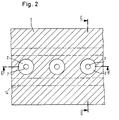
- FIG. 2 shows the section through the nozzle block indicated by line A-B in FIG. 1.
- Two sectional planes were placed in the figure, E-F (Fig. 3) and C-D (Fig. 4).
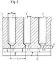
- Fig. 3 shows a section through the nozzle block parallel to the nozzle chambers (section E-F).
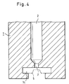
- Fig. 4 shows a section through a single nozzle transverse to the running direction of the band provided with recesses.
- the Figure illustrates how the tape is guided past the nozzle in a guide groove.
- the guide groove can be designed with lubricious material according to the requirements.
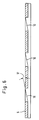
- Figure 5 is a top view of the grooved band.
- the elongated recesses in the middle are the passage openings for the adhesive.
- the sectional planes G-H and I-J result in FIGS. 6 and 7.
- Fig. 6 shows a section in the longitudinal direction through the band provided with recesses.
- Fig. 7 shows a section transverse to the longitudinal direction through the band provided with recesses.
- Fig. 1 shows schematically the essential features of a device for the contactless application of adhesive spots according to the inventive method.
- a row of interconnected nozzle chambers 2 are provided in a nozzle block 1 and are arranged next to one another in a line.
- the adhesive is pressed under pressure into the nozzle chambers via the feed units 3, excess adhesive that does not exit through the nozzles themselves can be returned to the adhesive depot via the discharge 4.
- a band 5 provided with recesses is guided around the nozzle block, the openings being made in a line parallel to the longitudinal axis of the band.
- a guide device (guide groove) for the band provided with recesses ensures that it is pressed so firmly against the nozzle openings 7 that no adhesive can escape between the band and the nozzle opening.
- the band 5 provided with recesses is guided past the nozzle openings 7, so that the alternating appearance of open and closed surfaces in front of the nozzles opens and exits or closes adhesive.
- a doctor device 8 is provided on the nozzle assembly, with which the tape provided with recesses is cleaned of any adhesive residues adhering to it.
- a moistening device 9 for the band provided with recesses additionally prevents the adhesive emerging from the nozzles from settling on the band.
- the substrate is guided past below the nozzle block.
- the distance from the substrate to the band provided with recesses is 0.1 to 5 mm, preferably 1.0 to 2 mm, in particular e.g. 1 to 1.2 mm.
- the distance between the outer nozzle openings arranged in line corresponds to the total width of the applied adhesive dot matrix.
- the spray unit must be designed accordingly or supplied with this adhesive.
- the mounting device for the spray unit is advantageously designed so that it can be easily replaced at any time.
- the section EF in FIG. 3 shows the conditions in the nozzle chambers 2 in the longitudinal direction to the band provided with recesses.
- the diameter of the nozzle opening 7 essentially determines the base diameter of the point of adhesive on the substrate and can expediently be in the range from 50 to 100 ⁇ m.
- the spacing 11 of the nozzle openings from one another also determines the spacing of the grid points of the adhesive coating transverse to the feed direction of the substrate.
- He is lying preferably in the range from 250 to 400 ⁇ m for printing removable adhesive labels, but can be enlarged or reduced depending on the desired product specification.
- the width of a nozzle chamber 12 and the height of the nozzle mouth 13 are not critical and depend on the most advantageous embodiment in each case.
- a section through a nozzle chamber transverse to the direction of the recessed belt also shows a section through the guide device 14 for the recessed belt, this groove-shaped guide device to reduce friction during the transport of the belt a lubricious material, e.g. Teflon, can be designed.
- a lubricious material e.g. Teflon
- the band 5 provided with recesses, which alternately opens and closes the nozzle outlet openings can be made of any material, as long as it meets the requirements for high flexibility, mechanical strength and resistance to the adhesive.
- a flexible metal band is particularly suitable.
- the band can be made thicker at the edges which engage in the guide groove.
- the recesses 10 on the longitudinal axis of the tape which alternately open and close the nozzle openings as the tape is transported past, expediently have a slightly larger diameter than the nozzle openings in order to prevent the adhesive from sticking under the tape. A diameter 1.2 to 2 times larger than the diameter of the nozzle openings has proven to be expedient for the recesses in the strip.
- the spacing 15 of the recesses corresponds to the spacing of the nozzle openings.
- the shape of the recesses on the belt can be circular, but it is preferably (see FIG. 5) designed such that a scissor-like, sharp cutting edge 16 arises to enable a smooth separation of the adhesive thread.
- the edge of the recess on the side of the band facing the nozzle opening has a sharp edge with a phase angle 17 of advantageously 5 to 17 °.
- the optimal phase angle depends on the viscosity of the adhesive used; with a viscosity of 10,000 to 25,000 mPas, an angle between 9 and 12 ° turned out to be particularly favorable.
- the tape can additionally be provided with an adhesive-repellent layer, for example Teflon, on the side facing away from the nozzle openings.
- Pressure-sensitive adhesive substrates are obtainable by the process according to the invention, the adhesive force of which, depending on the requirement, can be set from permanent adhesion to residue-free detachment and, if necessary, re-adhesive.
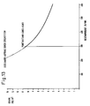
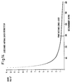
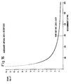
- the substrates have a grid of dome-shaped adhesive dots on one surface, the adhesive force depending on the distance between the adhesive dots, their diameter and the area of the adhesive coating compared to the total area of the substrate.
- the method according to the invention also allows a uniform and localized application of the adhesive coating, e.g. for specially shaped substrates.
- any material that can be provided with a pressure-sensitive adhesive layer can be used as the substrate.
- the method is particularly suitable for fabrics, sheets or foils, which can consist of paper, recycled paper, nonwovens, fabrics and / or plastic, provided that the adhesive adheres to them.
- the method according to the invention for producing labels, in particular labels that are pressure-sensitive and can be removed again without leaving any residue. These can also be designed as so-called sticky notes.
- Removable labels according to the invention can be removed from a substrate base without leaving any residue, it often not being necessary to provide the substrate base with an adhesive-repellent silicone layer in order to make it easier to remove.
- the method according to the invention thus combines the advantages of the screen printing method, exact and uniform coating, with the conventional spraying method, which above all allows quick and easy handling without having its specific disadvantages.
- a pressure-sensitive, removable label with an adhesive force of 50 N / cm width was produced.
- a base diameter of the adhesive dots of 100 ⁇ m and a grid width of 350 ⁇ m were set, the following device or process parameters being taken into account.
- Adhesive coating device Diameter of the nozzle openings: 70 ⁇ m Distance between the nozzle openings: 350 ⁇ m.
- the band has a Teflon layer on the side facing away from the nozzle.
- the band is made of metal. Phase angle of the edge of the recess on the metal band: 10 °.
- Diameter of the recesses in the metal band 120 ⁇ m.
- Diameter of the nozzle opening ( ⁇ m): 100 viscosity (mPa.s): 10,000 pressure (bar): 60,000 Diameter of the recess ( ⁇ m): 100 Nozzle opening open (ms): 0.1000 Nozzle opening closed (ms): 0.2000 Point spacing across ( ⁇ m): 1000.0 Diameter of the recess ( ⁇ m): 333 Distance between two recesses ( ⁇ m): 667 Layer thickness ( ⁇ m): 5 Points (m -2 ): 1.0 x 10 6
- Diameter of the nozzle opening ( ⁇ m): 100 viscosity (mPa.s): 10,000 pressure (bar): 60,000 Diameter of the recess ( ⁇ m): 100 Nozzle opening open (ms): 0.1000 Nozzle opening closed (ms): 0.2000 Point spacing across ( ⁇ m): 2000.0 Diameter of the recess ( ⁇ m): 667 Distance between two recesses ( ⁇ m): 1333 Layer thickness ( ⁇ m): 5 Points (m -2 ): 2.5 x 10 5
- Diameter of the nozzle opening 120 viscosity (mPa.s): 10,000 pressure (bar): 60,000 Diameter of the recess ( ⁇ m): 100 Nozzle opening open (ms): 0.1000 Nozzle opening closed (ms): 0.2000 Point spacing across ( ⁇ m): 1500.0 Diameter of the recess ( ⁇ m): 500 Distance between two recesses ( ⁇ m): 1000 Layer thickness ( ⁇ m): 6 Points (m -2 ): 4.4 x 10 5
- Diameter of the nozzle opening ( ⁇ m): 140 viscosity (mPa.s): 10,000 pressure (bar): 60,000 Diameter of the recess ( ⁇ m): 100 Nozzle opening open (ms): 0.1000 Nozzle opening closed (ms): 0.2000 Point spacing across ( ⁇ m): 1500.0 Diameter of the recess ( ⁇ m): 500 Distance between two recesses ( ⁇ m): 1000 Layer thickness ( ⁇ m): 9 Points (m -2 ): 4.4 x 10 5
- Diameter of the nozzle opening ( ⁇ m): 160 viscosity (mPa.s): 10,000 pressure (bar): 60,000 Diameter of the recess ( ⁇ m): 100 Nozzle opening open (ms): 0.1000 Nozzle opening closed (ms): 0.2000 Point spacing across ( ⁇ m): 1500.0 Diameter of the recess ( ⁇ m): 500 Distance between two recesses ( ⁇ m): 1000 Layer thickness ( ⁇ m): 11 Points (m -2 ): 4.4 x 10 5
- Diameter of the nozzle opening ( ⁇ m): 200 viscosity (mPa.s): 10,000 pressure (bar): 60,000 Diameter of the recess ( ⁇ m): 100 Nozzle opening open (ms): 0.1000 Nozzle opening closed (ms): 0.2000 Point spacing across ( ⁇ m): 1500.0 Diameter of the recess ( ⁇ m): 500 Distance between two recesses ( ⁇ m): 1000 Layer thickness ( ⁇ m): 17th Points (m -2 ): 4.4 x 10 5
- Diameter of the nozzle opening ( ⁇ m): 100 viscosity (mPa.s): 10,000 pressure (bar): 60,000 Diameter of the recess ( ⁇ m): 100 Nozzle opening open (ms): 0.1200 Nozzle opening closed (ms): 0.1800 Point spacing across ( ⁇ m): 1500.0 Diameter of the recess ( ⁇ m): 600 Distance between two recesses ( ⁇ m): 900 Layer thickness ( ⁇ m): 5 Points (m -2 ): 4.4 x 10 5
- Diameter of the nozzle opening ( ⁇ m): 100 viscosity (mPa.s): 10,000 pressure (bar): 60,000 Diameter of the recess ( ⁇ m): 100 Nozzle opening open (ms): 0.1500 Nozzle opening closed (ms): 0.1500 Point spacing across ( ⁇ m): 1500.0 Diameter of the recess ( ⁇ m): 750 Distance between two recesses ( ⁇ m): 750 Layer thickness ( ⁇ m): 7 Points (m -2 ): 4.4 x 10 5
- Diameter of the nozzle opening ( ⁇ m): 100 viscosity (mPa.s): 10,000 pressure (bar): 60,000 Diameter of the recess ( ⁇ m): 100 Nozzle opening open (ms): 0.1800 Nozzle opening closed (ms): 0.1200 Point spacing across ( ⁇ m): 1500.0 Diameter of the recess ( ⁇ m): 900 Distance between two recesses ( ⁇ m): 600 Layer thickness ( ⁇ m): 8th Points (m -2 ): 4.4 x 10 5
Landscapes
- Application Of Or Painting With Fluid Materials (AREA)
- Adhesives Or Adhesive Processes (AREA)
- Coating Apparatus (AREA)
Applications Claiming Priority (2)
| Application Number | Priority Date | Filing Date | Title |
|---|---|---|---|
| DE4124064A DE4124064C2 (de) | 1991-07-19 | 1991-07-19 | Verfahren und Vorrichtung zum Aufbringen von Klebstoffpunkten sowie haftklebendes Substrat |
| DE4124064 | 1991-07-19 |
Publications (2)
| Publication Number | Publication Date |
|---|---|
| EP0523589A1 EP0523589A1 (de) | 1993-01-20 |
| EP0523589B1 true EP0523589B1 (de) | 1997-05-28 |
Family
ID=6436610
Family Applications (1)
| Application Number | Title | Priority Date | Filing Date |
|---|---|---|---|
| EP92111887A Expired - Lifetime EP0523589B1 (de) | 1991-07-19 | 1992-07-13 | Berührungsloses Aufbringen von Klebstoffpunkten |
Country Status (3)
| Country | Link |
|---|---|
| EP (1) | EP0523589B1 (OSRAM) |
| AT (1) | ATE153568T1 (OSRAM) |
| DE (2) | DE4124064C2 (OSRAM) |
Cited By (2)
| Publication number | Priority date | Publication date | Assignee | Title |
|---|---|---|---|---|
| DE102006037318A1 (de) * | 2006-08-08 | 2008-02-14 | Celanese Emulsions Gmbh | Verfahren zur Applikation eines Dispersionsklebstoffes mittels Düsenauftrag und Verwendung von Dispersionsklebstoffen |
| US8785540B2 (en) | 2006-08-08 | 2014-07-22 | Celanese Emulsions Gmbh | Vinyl ester copolymer dispersions, their preparation and use |
Families Citing this family (13)
| Publication number | Priority date | Publication date | Assignee | Title |
|---|---|---|---|---|
| US5534114A (en) * | 1992-03-06 | 1996-07-09 | Philip Morris Incorporated | Method and apparatus for applying a material to a web |
| US5769947A (en) * | 1994-10-22 | 1998-06-23 | Itw Dynatech Gmbh Klebetechnik | Applicator for adhesive and corresponding nozzle plate |
| DE4437764A1 (de) * | 1994-10-22 | 1996-04-25 | Itw Dynatec Gmbh Klebetechnik | Vorrichtung zum Auftragen von Leim oder dergleichen und dafür geeignete Düsenplatte |
| IT1285967B1 (it) * | 1996-06-25 | 1998-06-26 | Gd Spa | Metodo e dispositivo per l'applicazione di materiale collante su materiale di incarto |
| US5961767A (en) * | 1997-05-15 | 1999-10-05 | Lucent Technologies, Inc. | Method for forming micron-sized and smaller liquid droplets |
| WO2000069571A1 (de) | 1999-05-17 | 2000-11-23 | A.W. Faber-Castell Unternehmensverwaltung Gmbh & Co. | Vorrichtung zum aufbringen erhabener strukturen aus kunststoffmaterial auf oberflächen |
| FI113527B (fi) * | 2002-12-31 | 2004-05-14 | Raute Oyj | Suutinyksikkö |
| WO2004065023A1 (de) * | 2003-01-20 | 2004-08-05 | Staempfli Paul | Vorrichtung zum austragen von leim |
| FR2886880B1 (fr) | 2005-06-14 | 2008-10-03 | Mgi France Sa | Machine numerique a jet pour depose d'un revetement sur un substrat |
| DE102014212940A1 (de) * | 2014-07-03 | 2016-01-07 | Fraunhofer-Gesellschaft zur Förderung der angewandten Forschung e.V. | Modul, System und Verfahren zum Auftragen eines viskosen Mediums auf eine Oberfläche und Verfahren zum Herstellen des Moduls |
| CN107458023A (zh) * | 2017-08-28 | 2017-12-12 | 芜湖润林包装材料有限公司 | 一种蜂窝板包装箱粘合剂喷涂装置 |
| CN112620000B (zh) * | 2020-12-24 | 2025-01-28 | 信利光电股份有限公司 | 一种狭缝涂布机刀头 |
| DE102023128194A1 (de) * | 2023-10-16 | 2025-04-17 | Khs Gmbh | Verteileinheit für eine Applikationseinrichtung, Applikationseinrichtung mit einer entsprechenden Verteileinheit, Beleimungsstation mit einer Vielzahl von Applikationseinrichtungen und Verfahren zum additiven Fertigen einer Verteileinheit |
Family Cites Families (11)
| Publication number | Priority date | Publication date | Assignee | Title |
|---|---|---|---|---|
| DE1288070B (de) * | 1969-01-30 | Planatolwerk W. Hesselmann, Chemische und Maschinenfabrik für Klebetechnik, 8200 Rosenheim: | Vorrichtung zum punktförmigen Auftragen von Klebstoff u. dgl. auf eine Materialbahn beispielsweise für die Endlosformular-Herstellung | |
| US2904448A (en) * | 1956-08-09 | 1959-09-15 | Sorg Adam | Method of making filter paper heat sealable |
| DE1131079B (de) * | 1960-09-21 | 1962-06-07 | Willy Hesselmann | Mundstueck zum Auftragen von Klebstoffen auf eine ueber eine Gegenwalze gefuehrte Papierbahn |
| DE1577888A1 (de) * | 1965-08-24 | 1969-07-31 | Hesselmann Planatolwerk H | Vorrichtung zum Auftragen von fluessigen Substanzen,insbesondere Klebstoff |
| AT314459B (de) * | 1971-12-06 | 1974-04-10 | Zimmer Peter | Verfahren zum Färben oder Bedrucken von Warenbahnen |
| DE2341091C3 (de) * | 1973-08-14 | 1978-10-12 | Planatolwerk Willy Hesselmann, Chemische Und Maschinenfabrik Fuer Klebetechnik, 8201 Thansau | Verschluß für eine Auftragevorrichtung für Klebstoffe u.dgl |
| CH613387A5 (en) * | 1975-07-28 | 1979-09-28 | Zimmer Peter Maschinenfabrik A | Process and device for applying patterns to a material, in particular to a web material |
| DE3638307A1 (de) * | 1986-11-10 | 1988-05-19 | Volker Ludwig | Vorrichtung zum auftragen von fluessigen, pastoesen oder plastischen substanzen auf ein substrat |
| DE3826395A1 (de) * | 1988-08-03 | 1990-02-15 | Volker Ludwig | Verfahren zum auftragen von fluessigen, pastoesen oder plastischen substanzen auf ein substrat |
| US4968534A (en) * | 1989-01-17 | 1990-11-06 | Npd Corp. | Method and apparatus for pattern impregnation of a porous web |
| DE4020420A1 (de) * | 1990-06-27 | 1992-01-02 | Volker Ludwig | Verfahren zum auftragen von fluessigen, pastoesen oder plastischen substanzen auf ein substrat |
-
1991
- 1991-07-19 DE DE4124064A patent/DE4124064C2/de not_active Expired - Fee Related
-
1992
- 1992-07-13 EP EP92111887A patent/EP0523589B1/de not_active Expired - Lifetime
- 1992-07-13 AT AT92111887T patent/ATE153568T1/de not_active IP Right Cessation
- 1992-07-13 DE DE59208534T patent/DE59208534D1/de not_active Expired - Fee Related
Cited By (2)
| Publication number | Priority date | Publication date | Assignee | Title |
|---|---|---|---|---|
| DE102006037318A1 (de) * | 2006-08-08 | 2008-02-14 | Celanese Emulsions Gmbh | Verfahren zur Applikation eines Dispersionsklebstoffes mittels Düsenauftrag und Verwendung von Dispersionsklebstoffen |
| US8785540B2 (en) | 2006-08-08 | 2014-07-22 | Celanese Emulsions Gmbh | Vinyl ester copolymer dispersions, their preparation and use |
Also Published As
| Publication number | Publication date |
|---|---|
| EP0523589A1 (de) | 1993-01-20 |
| ATE153568T1 (de) | 1997-06-15 |
| DE4124064C1 (OSRAM) | 1993-04-08 |
| DE4124064C2 (de) | 1996-04-25 |
| DE59208534D1 (de) | 1997-07-03 |
Similar Documents
| Publication | Publication Date | Title |
|---|---|---|
| EP0523589B1 (de) | Berührungsloses Aufbringen von Klebstoffpunkten | |
| DE69317706T2 (de) | Apparat und Verfahren zum Auftrag von diskontinuierlichen Beschichtungen | |
| DE69314343T2 (de) | Vorrichtung und verfahren zum aufbringen von schaumbeschichtungen | |
| EP0003790B1 (de) | Vorrichtung zum Beschichten einer sich bewegenden Bahn | |
| AT391899B (de) | Verfahren zum auftrag von partiellen oberflaechenbeschichtungen auf textile substrate und eine vorrichtung zur durchfuehrung des verfahrens | |
| DE69815400T2 (de) | Klebeband mit streifenförmiger haftkleberanordnung | |
| EP0328925B1 (de) | Haftklebrige Flächengebilde | |
| DE69501405T2 (de) | Perforierte siebdruckschablone zum aufbringen und dosieren von mehr oder weniger dicken schichten eines viskosen produktes | |
| DE2557551B1 (de) | Verfahren und vorrichtung zum auftragen von fluessigkeiten, insbesondere von fluessigen klebstoffen auf bahnfoermiges material | |
| DE2142345C2 (de) | Verfahren zur Herstellung einer Windel u. dgl. | |
| WO2009068572A1 (de) | Gegenlage düsenbeleimung | |
| DE102015204975B4 (de) | Auftragswerk für Papier-, Karton- oder Tissuebahn | |
| DE3907846B4 (de) | Beschichtungsvorrichtung und Verfahren zum Auftragen eines Überzugmediums auf einen ununterbrochen laufenden flexiblen Träger | |
| EP1115501A1 (de) | Vorrichtung und verfahren zum partiellen auftragen einer oberflächenbeschichtung und atmungsaktive folie mit einer partiellen oberflächenbeschichtung | |
| DE3900619C2 (OSRAM) | ||
| EP2146003A2 (de) | Vorhang-Auftragswerk | |
| DE102017128240A1 (de) | Verfahren und System zum Auftragen einer Substanzschicht auf eine sich bewegende Faserbahn mittels Schaumaufbringung | |
| EP1765950B1 (de) | Zumindest teilflächig mit selbstklebemasse ausgerüstetes flächengebilde | |
| DE1652320B2 (de) | Vorrichtung zur Herstellung eines Überzugs auf einem sich bewegenden bahnförmigen Schichtträger | |
| EP1632347A1 (de) | Verfahren und Vorrichtung zum Verbinden flächiger Materialien | |
| DE3438489A1 (de) | Verfahren zur oberflaechenkaschierung selbsttragender formteile, beispielsweise fuer die innenverkleidung von kraftfahrzeugen, und vorrichtung zur durchfuehrung des verfahrens | |
| EP2216439A1 (de) | Verfahren zum Beschichten eines Bandes, inbesondere einer Papiermaschinenbespannung | |
| DE2140091A1 (de) | Verfahren und Vorrichtung zur An fertigung von Fasermaterial | |
| EP0999814B1 (de) | Verfahren zum herstellen von verschlusselementen bei saugfähigen hygieneartikeln zum einmaligen gebrauch | |
| DE3235151A1 (de) | Einrichtung zum auftragen von klebstoffen in mehreren schichten auf einen traeger bei der herstellung von selbstklebebaendern |
Legal Events
| Date | Code | Title | Description |
|---|---|---|---|
| PUAI | Public reference made under article 153(3) epc to a published international application that has entered the european phase |
Free format text: ORIGINAL CODE: 0009012 |
|
| AK | Designated contracting states |
Kind code of ref document: A1 Designated state(s): AT BE CH DE DK ES FR GB GR IT LI LU MC NL PT SE |
|
| 17P | Request for examination filed |
Effective date: 19930706 |
|
| 17Q | First examination report despatched |
Effective date: 19940915 |
|
| GRAG | Despatch of communication of intention to grant |
Free format text: ORIGINAL CODE: EPIDOS AGRA |
|
| GRAH | Despatch of communication of intention to grant a patent |
Free format text: ORIGINAL CODE: EPIDOS IGRA |
|
| GRAH | Despatch of communication of intention to grant a patent |
Free format text: ORIGINAL CODE: EPIDOS IGRA |
|
| GRAA | (expected) grant |
Free format text: ORIGINAL CODE: 0009210 |
|
| PGFP | Annual fee paid to national office [announced via postgrant information from national office to epo] |
Ref country code: DE Payment date: 19970520 Year of fee payment: 6 |
|
| AK | Designated contracting states |
Kind code of ref document: B1 Designated state(s): AT BE CH DE DK ES FR GB GR IT LI LU MC NL PT SE |
|
| PG25 | Lapsed in a contracting state [announced via postgrant information from national office to epo] |
Ref country code: NL Free format text: LAPSE BECAUSE OF FAILURE TO SUBMIT A TRANSLATION OF THE DESCRIPTION OR TO PAY THE FEE WITHIN THE PRESCRIBED TIME-LIMIT Effective date: 19970528 Ref country code: GR Free format text: LAPSE BECAUSE OF FAILURE TO SUBMIT A TRANSLATION OF THE DESCRIPTION OR TO PAY THE FEE WITHIN THE PRESCRIBED TIME-LIMIT Effective date: 19970528 Ref country code: ES Free format text: THE PATENT HAS BEEN ANNULLED BY A DECISION OF A NATIONAL AUTHORITY Effective date: 19970528 Ref country code: DK Effective date: 19970528 |
|
| REF | Corresponds to: |
Ref document number: 153568 Country of ref document: AT Date of ref document: 19970615 Kind code of ref document: T |
|
| REG | Reference to a national code |
Ref country code: CH Ref legal event code: NV Representative=s name: BUECHEL & PARTNER AG PATENTBUERO Ref country code: CH Ref legal event code: EP |
|
| GBT | Gb: translation of ep patent filed (gb section 77(6)(a)/1977) |
Effective date: 19970528 |
|
| REF | Corresponds to: |
Ref document number: 59208534 Country of ref document: DE Date of ref document: 19970703 |
|
| PGFP | Annual fee paid to national office [announced via postgrant information from national office to epo] |
Ref country code: GB Payment date: 19970708 Year of fee payment: 6 |
|
| PG25 | Lapsed in a contracting state [announced via postgrant information from national office to epo] |
Ref country code: LU Free format text: LAPSE BECAUSE OF NON-PAYMENT OF DUE FEES Effective date: 19970713 Ref country code: AT Free format text: LAPSE BECAUSE OF NON-PAYMENT OF DUE FEES Effective date: 19970713 |
|
| PGFP | Annual fee paid to national office [announced via postgrant information from national office to epo] |
Ref country code: FR Payment date: 19970725 Year of fee payment: 6 |
|
| PG25 | Lapsed in a contracting state [announced via postgrant information from national office to epo] |
Ref country code: LI Free format text: LAPSE BECAUSE OF NON-PAYMENT OF DUE FEES Effective date: 19970731 Ref country code: CH Free format text: LAPSE BECAUSE OF NON-PAYMENT OF DUE FEES Effective date: 19970731 Ref country code: BE Free format text: LAPSE BECAUSE OF NON-PAYMENT OF DUE FEES Effective date: 19970731 |
|
| ET | Fr: translation filed | ||
| PG25 | Lapsed in a contracting state [announced via postgrant information from national office to epo] |
Ref country code: SE Effective date: 19970828 Ref country code: PT Effective date: 19970828 |
|
| NLV1 | Nl: lapsed or annulled due to failure to fulfill the requirements of art. 29p and 29m of the patents act | ||
| BERE | Be: lapsed |
Owner name: ZWECKFORM BURO-PRODUKTE G.M.B.H. Effective date: 19970731 |
|
| PG25 | Lapsed in a contracting state [announced via postgrant information from national office to epo] |
Ref country code: MC Free format text: LAPSE BECAUSE OF NON-PAYMENT OF DUE FEES Effective date: 19980131 |
|
| REG | Reference to a national code |
Ref country code: CH Ref legal event code: PL |
|
| PLBE | No opposition filed within time limit |
Free format text: ORIGINAL CODE: 0009261 |
|
| STAA | Information on the status of an ep patent application or granted ep patent |
Free format text: STATUS: NO OPPOSITION FILED WITHIN TIME LIMIT |
|
| 26N | No opposition filed | ||
| PG25 | Lapsed in a contracting state [announced via postgrant information from national office to epo] |
Ref country code: GB Free format text: LAPSE BECAUSE OF NON-PAYMENT OF DUE FEES Effective date: 19980713 |
|
| GBPC | Gb: european patent ceased through non-payment of renewal fee |
Effective date: 19980713 |
|
| PG25 | Lapsed in a contracting state [announced via postgrant information from national office to epo] |
Ref country code: FR Free format text: LAPSE BECAUSE OF NON-PAYMENT OF DUE FEES Effective date: 19990331 |
|
| PG25 | Lapsed in a contracting state [announced via postgrant information from national office to epo] |
Ref country code: DE Free format text: LAPSE BECAUSE OF NON-PAYMENT OF DUE FEES Effective date: 19990501 |
|
| REG | Reference to a national code |
Ref country code: FR Ref legal event code: ST |
|
| PG25 | Lapsed in a contracting state [announced via postgrant information from national office to epo] |
Ref country code: IT Free format text: LAPSE BECAUSE OF NON-PAYMENT OF DUE FEES Effective date: 20050713 |