EP0519381B1 - Fahrradpedal - Google Patents
Fahrradpedal Download PDFInfo
- Publication number
- EP0519381B1 EP0519381B1 EP92110075A EP92110075A EP0519381B1 EP 0519381 B1 EP0519381 B1 EP 0519381B1 EP 92110075 A EP92110075 A EP 92110075A EP 92110075 A EP92110075 A EP 92110075A EP 0519381 B1 EP0519381 B1 EP 0519381B1
- Authority
- EP
- European Patent Office
- Prior art keywords
- pedal
- ball bearings
- pedal shaft
- small diameter
- bearing
- Prior art date
- Legal status (The legal status is an assumption and is not a legal conclusion. Google has not performed a legal analysis and makes no representation as to the accuracy of the status listed.)
- Expired - Lifetime
Links
- 238000010276 construction Methods 0.000 description 10
- 238000005452 bending Methods 0.000 description 3
- 244000145845 chattering Species 0.000 description 3
- 230000004323 axial length Effects 0.000 description 2
- 239000012141 concentrate Substances 0.000 description 1
- 238000006073 displacement reaction Methods 0.000 description 1
- 239000002184 metal Substances 0.000 description 1
- 125000006850 spacer group Chemical group 0.000 description 1
Images

Classifications
-
- B—PERFORMING OPERATIONS; TRANSPORTING
- B62—LAND VEHICLES FOR TRAVELLING OTHERWISE THAN ON RAILS
- B62M—RIDER PROPULSION OF WHEELED VEHICLES OR SLEDGES; POWERED PROPULSION OF SLEDGES OR SINGLE-TRACK CYCLES; TRANSMISSIONS SPECIALLY ADAPTED FOR SUCH VEHICLES
- B62M3/00—Construction of cranks operated by hand or foot
- B62M3/08—Pedals
-
- Y—GENERAL TAGGING OF NEW TECHNOLOGICAL DEVELOPMENTS; GENERAL TAGGING OF CROSS-SECTIONAL TECHNOLOGIES SPANNING OVER SEVERAL SECTIONS OF THE IPC; TECHNICAL SUBJECTS COVERED BY FORMER USPC CROSS-REFERENCE ART COLLECTIONS [XRACs] AND DIGESTS
- Y10—TECHNICAL SUBJECTS COVERED BY FORMER USPC
- Y10T—TECHNICAL SUBJECTS COVERED BY FORMER US CLASSIFICATION
- Y10T74/00—Machine element or mechanism
- Y10T74/21—Elements
- Y10T74/2164—Cranks and pedals
- Y10T74/2168—Pedals
Definitions
- the present invention relates to a bicycle pedal having a pedal body rotatably supported through bearings on a pedal shaft attached to a crank arm.
- the pedal shaft includes a distal portion having a smaller diameter than a proximal portion attached to the crank arm.
- a pair of ball bearings are mounted between the pedal body and the small diameter distal portion of the pedal shaft.
- the proximal portion of the pedal shaft is formed to have a large diameter to secure sufficient strength against a strong bending moment.
- the distal portion of the pedal shaft is free from a strong bending moment, and may therefore have a small diameter for accommodating the pair of ball bearings axially spaced from each other. With the pedal body supported through the ball bearings mounted on the small diameter portion, the prior construction avoids the pedal having an excessive thickness as a whole.
- the pedal body is rotatably supported through only the pair of ball bearings.
- the pedal body which is trodden directly by the cyclist's foot, and the pedal shaft are in point contact with the bearing balls. Consequently, the load of the treading force concentrates on positions of the point contact. Such positions tend to wear quickly, to impair durability of the pedal construction. The wear may result in displacement of the balls axially of the pedal shaft, whereby chattering occurs between the pedal shaft and pedal body to obstruct a smooth pedaling action.
- the object of the present invention is to eliminate the disadvantage of the prior art noted above, and provide an improved bicycle pedal for attaching to a crank arm.
- a pedal has a pedal shaft including an attachment portion formed at one end thereof and attached to the crank arm, the pedal shaft defining a small diameter portion formed adjacent the other end thereof and having a smaller diameter than the attachment portion, and a first and a second ball bearings arranged in a region of the small diameter portion and spaced apart from each other axially of the pedal shaft.
- the pedal may have a reduced axial length too.
- a bicycle pedal comprising a needle bearing disposed adjacent the ball bearings, and a pedal body rotatably supported on the small diameter portion through the first and second ball bearings and the needle bearing, the pedal body defining at least one tread on a surface thereof.
- the pair of ball bearings receive part of the treading force transmitted through the pedal body, and the respective ball bearings effectively prevent the pedal body from moving outwardly and inwardly along the axis of the pedal shaft.
- the needle bearing also receives part of the treading force transmitted through the pedal body, and rotatably supports the pedal body through line contact. Consequently, this construction produces less right and left chattering due to wear of portions of sliding contact than in the prior art.
- the present invention allows the pedal body to have a reduced inward thickness while securing a sufficient strength of the pedal shaft.
- the outward thickness of the pedal body which is determined on the basis of the inward thickness may also be reduced.
- the tread may be formed on the pedal body close to the crank arm to secure a large road clearance, thereby to provide the advantage of transmitting the treading force to the pedal shaft with high efficiency.
- the pair of ball bearings enable reliable position setting of the pedal body axially of the pedal shaft, while the needle bearing reduces the possibility of right and left chattering due to wear of the bearing region. This construction assures a constant pedaling touch over a long period.
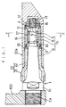
- Fig. 1 shows a bicycle pedal having a pedal shaft 1 attached in a cantilever mode to a free end of a crank arm 100 of a bicycle crankset.
- the pedal shaft 1 rotatably supports a pedal body 20 defining a tread 22a.
- the pedal shaft 1 includes a threaded attaching portion 1a for attaching to the crank arm 100, a shank portion 1b aligned with the attaching portion 1a and extending axially of the pedal shaft 1, and a turn flange 1c having an angular section and disposed between the attaching portion 1a and shank portion 1b.
- the shank portion 1b includes a distal region having a smaller diameter than the attaching portion 1a.
- a bearing device is mounted between the small diameter region and the pedal body 20 opposed thereto for rotatably supporting the pedal body 20.
- the shank portion 1b is constricted stagewise within a range to withstand a maximum bending moment applied by cyclist's treading action.
- the small diameter region has a pair of first and second ball bearings 3 and 4, and a needle bearing 5 disposed adjacent thereto, for rotatably supporting the pedal body 20. That is, the shank portion 1b has a proximal portion 6 adjacent the crank arm 100 and, formed successively forwardly or outwardly therefrom, a first intermediate small diameter portion 7, a second intermediate small diameter portion 8, and a minimum diameter portion 9 to constitute the small diameter region.
- the first intermediate small diameter portion 7 defines an outwardly oriented race 10 of the first ball bearing 3.
- the minimum diameter portion 9 is threaded to have a ball presser 12 screwed thereto and having an inwardly oriented race 11 of the second ball bearing 4.
- the ball presser 12 is fixed in place by a lock nut 13.
- An outer bearing member 14 extends radially outwardly of the first intermediate small diameter portion 7, second intermediate small diameter portion 8 and minimum diameter portion 9.
- the outer bearing member 14 defines, at an end thereof opposed to the crank arm 100, an inwardly oriented race 15 of the first ball bearing 3 opposed to the outwardly oriented race 10.
- the outer bearing member 14 defines, at the other end thereof, an outwardly oriented race 16 of the second ball bearing 4 opposed to the inwardly oriented race 11.
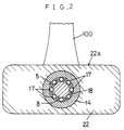
- the needle bearing 5 is disposed between the first ball bearing 3 and second ball bearing 4 and between an outer periphery of the second intermediate small diameter portion 8 and an inner periphery of the outer bearing member 14. As shown in Fig. 2, the needle bearing 5 includes a plurality of needles 17 arranged at intervals circumferentially thereof, with spacers 18 mounted between adjacent pairs of the needles 17 to constantly maintain fixed intervals therebetween.
- the pedal body 20 is formed of plastic and has a two-part construction including a first member 21 fitted on a region of the pedal shaft 1 adjacent the crank arm 100, and a second member 22 extending axially outwardly of the pedal shaft 1, partly overlapping the first member 21 and surrounding the distal region of the pedal shaft 1.
- the second member 22 is fitted on an outer periphery of the outer bearing member 14.
- the tread 22a is defined on an outer surface of the second member 22.
- the pedal body 20 may be formed of a metal and may be split into two, upper and lower, parts.
- the pedal body 20 is rotatably supported on the pedal shaft 1 through the pair of first and second ball bearings 3 and 4 and the needle bearing 5 arranged in the distal region of the pedal shaft 1. A large part of the load resulting from pedaling action is borne by the needle bearing 5. The pedal body 20 is prevented from moving inwardly relative to the pedal shaft 1 by the first ball bearing 3, and from moving outwardly by the second ball bearing 4.
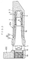
- Fig. 3 shows a second embodiment in which a pair of ball bearings 3 and 4 are arranged in a distal region of the pedal shaft 1, and a needle bearing 5 is disposed in a region thereof closer to the crank arm 100.
- like reference numerals are used to identify like parts in Fig. 1 to avoid unnecessary repetition of the description.
- Fig. 4 shows a third embodiment in which a needle bearing 5 is disposed on an extreme end of the pedal shaft 1, with a pair of ball bearings 3 and 4 arranged in a region thereof closer to the crank arm 100.
- like reference numerals are used to identify like parts in Fig. 1 to avoid unnecessary repetition of the description.
Landscapes
- Engineering & Computer Science (AREA)
- Chemical & Material Sciences (AREA)
- Combustion & Propulsion (AREA)
- Transportation (AREA)
- Mechanical Engineering (AREA)
- Sliding-Contact Bearings (AREA)
- Rolling Contact Bearings (AREA)
- Mechanical Control Devices (AREA)
Claims (5)
- Fahrradpedal zur Befestigung an einem Kurbelarm (100), umfassend:
eine Pedalwelle (1) mit einem Befestigungsbereich (1a) der an deren einen Ende ausgebildet ist und geeignet ist, an dem Kurbelarm (100) befestigt zu werden, wobei die Pedalwelle (1) einen Bereich (7, 8, 9) kleinen Durchmessers begrenzt, der in der Nähe von deren anderem Ende ausgebildet ist und einen kleineren Durchmesser als der Befestigungsbereich (1a) hat,
ein erstes (3) und ein zweites (4) Kugellager, die in einem Abschnitt des Bereichs mit kleinem Durchmesser angeordnet und voneinander in axialer Richtung durch die Pedalwelle (1) beabstandet sind,
ein Nadellager (5), das in der Nähe der Kugellager (3, 4) angeordnet ist, und
einen Pedalkörper (20) der an dem Bereich (7, 8, 9) mit kleinen Durchmesser durch das erste (3) und das zweite (4) Kugellager und das Nadellager (15) drehbar gelagert ist, wobei der Pedalkörper (20) mindestens eine Trittfläche (22a) auf einer Oberfläche davon begrenzt. - Fahrradpedal nach Anspruch 1, dadurch gekennzeichnet, daß das Nadellager (5) zwischen dem ersten Kugellager (3) und dem zweiten Kugellager (4) angeordnet ist.
- Fahrradpedal nach Anspruch 1, dadurch gekennzeichnet, daß das Nadellager (5) näher an dem Kurbelarm (100) als das erste und das zweite Kugellager (3, 4) angeordnet ist.
- Fahrradpedal nach Anspruch 1, dadurch gekennzeichnet, daß das Nadellager (5) näher an dem äußersten Ende der Pedalwelle (1) als das erste und zweite Kugellager (3, 4) angeordnet ist.
- Fahrzeugpedal nach Anspruch 1, dadurch gekennzeichnet, daß der Pedalkörper (20) ein erstes Element (21), das einen Bereich der Pedalwelle (1) in der Nähe des Kurbelarms (100) umgibt, und ein zweites Element (22)umfaßt, das sich axial nach außen von der Pedalwelle (1) erstreckt und mindestens einen Teil des ersten Elements (21) umgibt, wobei das Nadellager (5) und das erste und zweite Kugellager (3, 4) zwischen dem zweiten Element (22) und dem Bereich (7, 8, 9) mit kleinem Durchmesser angeordnet sind.
Applications Claiming Priority (2)
| Application Number | Priority Date | Filing Date | Title |
|---|---|---|---|
| JP46173/91U | 1991-06-19 | ||
| JP1991046173U JP2546149Y2 (ja) | 1991-06-19 | 1991-06-19 | 自転車用ペダル |
Publications (2)
| Publication Number | Publication Date |
|---|---|
| EP0519381A1 EP0519381A1 (de) | 1992-12-23 |
| EP0519381B1 true EP0519381B1 (de) | 1995-09-13 |
Family
ID=12739638
Family Applications (1)
| Application Number | Title | Priority Date | Filing Date |
|---|---|---|---|
| EP92110075A Expired - Lifetime EP0519381B1 (de) | 1991-06-19 | 1992-06-15 | Fahrradpedal |
Country Status (4)
| Country | Link |
|---|---|
| US (1) | US5379665A (de) |
| EP (1) | EP0519381B1 (de) |
| JP (1) | JP2546149Y2 (de) |
| DE (1) | DE69204756T2 (de) |
Families Citing this family (26)
| Publication number | Priority date | Publication date | Assignee | Title |
|---|---|---|---|---|
| US5727429A (en) * | 1996-08-26 | 1998-03-17 | Shimano, Inc. | Low profile bicycle pedal and cleat assembly |
| US5778739A (en) * | 1996-08-26 | 1998-07-14 | Shimano, Inc. | Bicycle pedal with gap adjusting mechanism |
| US5755144A (en) * | 1996-08-26 | 1998-05-26 | Shimano, Inc. | Low profile bicycle pedal with top and bottom side clamping arrangements |
| US5992266A (en) | 1996-09-03 | 1999-11-30 | Jonathan R. Heim | Clipless bicycle pedal |
| FR2777856B1 (fr) * | 1998-04-27 | 2000-06-23 | Look Cycle | Pedale de bicyclette a palier hydrostatique |
| US6227071B1 (en) * | 1999-09-07 | 2001-05-08 | William Blake Coombe | Axle and bearing arrangement for a bicycle pedal |
| US6874387B2 (en) | 2002-05-01 | 2005-04-05 | Michael J. Vaughn | Quick release bicycle pedal mounting connector |
| DE102005004310A1 (de) * | 2005-01-31 | 2006-08-03 | Schaeffler Kg | Fahrradpedale |
| DE102005027516A1 (de) * | 2005-06-15 | 2006-12-21 | Schaeffler Kg | Pedale |
| WO2009010046A2 (de) * | 2007-07-13 | 2009-01-22 | David Linden | Fahrradpedal |
| EP2020339B1 (de) | 2007-07-31 | 2012-03-28 | Micronas GmbH | Auslösevorrichtung für eine Sicherheitseinrichtung in einem Kraftfahrzeug |
| US8061236B2 (en) * | 2007-09-20 | 2011-11-22 | Bear Corporation | Bicycle pedal |
| US9003921B2 (en) * | 2007-10-10 | 2015-04-14 | The Hive Global | Removable pedal platform |
| US8714052B2 (en) | 2011-05-19 | 2014-05-06 | Specialized Bicycle Components, Inc. | Bicycle pedal |
| TWI450840B (zh) * | 2011-11-18 | 2014-09-01 | Vp Components Co Ltd | 一體式軸芯踏板 |
| US20130180355A1 (en) * | 2012-01-17 | 2013-07-18 | Vp Components Co., Ltd. | Modularized bicycle pedal |
| US10221887B2 (en) | 2012-12-06 | 2019-03-05 | The Hive Global, Inc | Self locking bearing preload adjuster |
| US10562588B2 (en) | 2015-09-01 | 2020-02-18 | The Hive Global, Inc | Bicycle cassette with locking connection |
| EP3419887B1 (de) | 2016-03-24 | 2024-08-28 | The Hive Global, Inc. | Fahrradkurbel mit spindelbefestigungsstruktur |
| US10358184B2 (en) * | 2017-07-28 | 2019-07-23 | Shimano Inc. | Bicycle pedal |
| CN111542471A (zh) | 2017-08-21 | 2020-08-14 | 劲锋铁马股份有限公司 | 具有夹紧连接的自行车塔轮 |
| US11932351B2 (en) | 2020-07-17 | 2024-03-19 | The Hive Global, Inc. | Conical bicycle cassette sprocket structure |
| US11858587B2 (en) | 2020-10-06 | 2024-01-02 | Shimano Inc. | Bicycle pedal |
| US11939027B2 (en) | 2020-12-22 | 2024-03-26 | Shimano Inc. | Bicycle pedal |
| US12233975B2 (en) | 2021-03-26 | 2025-02-25 | The Hive Global Inc. | Telescopic bicycle seatpost with adjustable height and fixed frame insertion |
| US12030586B2 (en) | 2021-07-12 | 2024-07-09 | The Hive Global, Inc. | Seal for bicycle crank with differential chainring motion |
Family Cites Families (14)
| Publication number | Priority date | Publication date | Assignee | Title |
|---|---|---|---|---|
| DE2111891A1 (de) * | 1971-03-12 | 1972-09-28 | Union Sils Van De Loo & Co | Pedal fuer Fahrraeder |
| JPS56128288A (en) * | 1980-03-12 | 1981-10-07 | Senkichirou Kimura | Power saving nimble-footed pedal for bicycle |
| JPS60111790A (ja) * | 1983-11-22 | 1985-06-18 | Toshiba Mach Co Ltd | 熱線の遮光装置 |
| FR2591989B1 (fr) * | 1985-12-24 | 1992-02-28 | Beyl Jean Joseph Alfred | Pedale de bicyclette, ou d'engin analogue |
| JPH0681394B2 (ja) * | 1985-07-03 | 1994-10-12 | 古河電気工業株式会社 | ゴム,プラスチツクケ−ブル接続部の組立方法 |
| JPH0244630Y2 (de) * | 1986-01-23 | 1990-11-27 | ||
| JPS62244630A (ja) * | 1986-04-16 | 1987-10-26 | 株式会社アイジー技術研究所 | 複合パネルの製造方法 |
| IT210658Z2 (it) * | 1987-03-16 | 1989-01-11 | Campagnolo Spa | Dispositivo di sopporto del pedale per biciclette e simili |
| JPS63172795U (de) * | 1987-04-30 | 1988-11-09 | ||
| JPS6444889U (de) * | 1987-09-14 | 1989-03-17 | ||
| DD278110A1 (de) * | 1988-12-16 | 1990-04-25 | Ifa Motorenwerke | Imitationsmittel fuer vx-aerosole |
| JPH01237284A (ja) * | 1989-01-27 | 1989-09-21 | Yamaha Motor Co Ltd | 自動二輪車のエンジンユニット |
| FR2661651B1 (fr) * | 1990-05-04 | 1995-09-01 | Berenger Daniel | Pedale de velo mobile sur 3 axes, a liberte reglable. |
| US5207118A (en) * | 1991-09-20 | 1993-05-04 | Chen Chia Ching | Pedal shaft core |
-
1991
- 1991-06-19 JP JP1991046173U patent/JP2546149Y2/ja not_active Expired - Lifetime
-
1992
- 1992-06-04 US US07/893,544 patent/US5379665A/en not_active Expired - Lifetime
- 1992-06-15 DE DE69204756T patent/DE69204756T2/de not_active Expired - Lifetime
- 1992-06-15 EP EP92110075A patent/EP0519381B1/de not_active Expired - Lifetime
Also Published As
| Publication number | Publication date |
|---|---|
| US5379665A (en) | 1995-01-10 |
| DE69204756T2 (de) | 1996-02-22 |
| EP0519381A1 (de) | 1992-12-23 |
| JPH04137994U (ja) | 1992-12-22 |
| DE69204756D1 (de) | 1995-10-19 |
| JP2546149Y2 (ja) | 1997-08-27 |
Similar Documents
| Publication | Publication Date | Title |
|---|---|---|
| EP0519381B1 (de) | Fahrradpedal | |
| JPH0244630Y2 (de) | ||
| US4873890A (en) | Pedal for a bicycle | |
| AU2157599A (en) | Wheel suspension assembly | |
| US4411169A (en) | Pedal for a bicycle | |
| EP0508328B1 (de) | Tretlager für Fahrrad zur Lagerung von Mehrfach-Kettenrad | |
| JPH0880889A (ja) | 自転車用アシストモータの制御方法 | |
| EP0928733A3 (de) | Lenksäule für ein Kraftfahrzeug | |
| US11421723B2 (en) | Support structure | |
| JP2000095120A (ja) | 電動式パワーステアリング装置におけるピニオン軸の支持構造 | |
| JP2529470Y2 (ja) | プロペラシャフトの連結部構造 | |
| EP0791532A3 (de) | Fahrradketten-Radplatte | |
| GB2189557A (en) | Improvements in bearings for wheels | |
| EP1442973A2 (de) | Tretkurbel für Fahrräder | |
| EP1993900B1 (de) | Fahrradtretkurbel mit biomechanischer hebelverstellvorrichtung | |
| JP3624965B2 (ja) | 荷重センサ付き軸受装置 | |
| JP7717225B2 (ja) | 電動アシスト自転車における踏力検出機構 | |
| EP1403095A3 (de) | Radlagervorrichtung | |
| JP2502770Y2 (ja) | 車輪用軸受装置 | |
| EP0805091A3 (de) | Erfassen des Drehmoments in der Lenkwelle einer schwenkbaren Lenksäule | |
| JPS5855107Y2 (ja) | 自転車用ペダル | |
| CN109305280B (zh) | 自行车踏板 | |
| JP3193299B2 (ja) | スピードセンサ | |
| JPH0134635Y2 (de) | ||
| KR0137679B1 (ko) | 보올 스터드형 시프트 레버 |
Legal Events
| Date | Code | Title | Description |
|---|---|---|---|
| PUAI | Public reference made under article 153(3) epc to a published international application that has entered the european phase |
Free format text: ORIGINAL CODE: 0009012 |
|
| AK | Designated contracting states |
Kind code of ref document: A1 Designated state(s): DE FR GB IT |
|
| 17P | Request for examination filed |
Effective date: 19930210 |
|
| 17Q | First examination report despatched |
Effective date: 19941115 |
|
| GRAA | (expected) grant |
Free format text: ORIGINAL CODE: 0009210 |
|
| AK | Designated contracting states |
Kind code of ref document: B1 Designated state(s): DE FR GB IT |
|
| REF | Corresponds to: |
Ref document number: 69204756 Country of ref document: DE Date of ref document: 19951019 |
|
| ITF | It: translation for a ep patent filed | ||
| ET | Fr: translation filed | ||
| PLBE | No opposition filed within time limit |
Free format text: ORIGINAL CODE: 0009261 |
|
| STAA | Information on the status of an ep patent application or granted ep patent |
Free format text: STATUS: NO OPPOSITION FILED WITHIN TIME LIMIT |
|
| 26N | No opposition filed | ||
| REG | Reference to a national code |
Ref country code: GB Ref legal event code: IF02 |
|
| PGFP | Annual fee paid to national office [announced via postgrant information from national office to epo] |
Ref country code: GB Payment date: 20050615 Year of fee payment: 14 |
|
| PG25 | Lapsed in a contracting state [announced via postgrant information from national office to epo] |
Ref country code: GB Free format text: LAPSE BECAUSE OF NON-PAYMENT OF DUE FEES Effective date: 20060615 |
|
| GBPC | Gb: european patent ceased through non-payment of renewal fee |
Effective date: 20060615 |
|
| PGFP | Annual fee paid to national office [announced via postgrant information from national office to epo] |
Ref country code: IT Payment date: 20070622 Year of fee payment: 16 |
|
| PGFP | Annual fee paid to national office [announced via postgrant information from national office to epo] |
Ref country code: FR Payment date: 20070608 Year of fee payment: 16 |
|
| REG | Reference to a national code |
Ref country code: FR Ref legal event code: ST Effective date: 20090228 |
|
| PG25 | Lapsed in a contracting state [announced via postgrant information from national office to epo] |
Ref country code: IT Free format text: LAPSE BECAUSE OF NON-PAYMENT OF DUE FEES Effective date: 20080615 Ref country code: FR Free format text: LAPSE BECAUSE OF NON-PAYMENT OF DUE FEES Effective date: 20080630 |
|
| PGFP | Annual fee paid to national office [announced via postgrant information from national office to epo] |
Ref country code: DE Payment date: 20110608 Year of fee payment: 20 |
|
| REG | Reference to a national code |
Ref country code: DE Ref legal event code: R071 Ref document number: 69204756 Country of ref document: DE |
|
| REG | Reference to a national code |
Ref country code: DE Ref legal event code: R071 Ref document number: 69204756 Country of ref document: DE |
|
| PG25 | Lapsed in a contracting state [announced via postgrant information from national office to epo] |
Ref country code: DE Free format text: LAPSE BECAUSE OF EXPIRATION OF PROTECTION Effective date: 20120616 |