EP0518366B1 - Verfahren und Vorrichtung zur Herstellung von LANGMUIR-BLODGETT-Filmen - Google Patents
Verfahren und Vorrichtung zur Herstellung von LANGMUIR-BLODGETT-Filmen Download PDFInfo
- Publication number
- EP0518366B1 EP0518366B1 EP92109936A EP92109936A EP0518366B1 EP 0518366 B1 EP0518366 B1 EP 0518366B1 EP 92109936 A EP92109936 A EP 92109936A EP 92109936 A EP92109936 A EP 92109936A EP 0518366 B1 EP0518366 B1 EP 0518366B1
- Authority
- EP
- European Patent Office
- Prior art keywords
- region
- monomolecular film
- film
- monomolecular
- water
- Prior art date
- Legal status (The legal status is an assumption and is not a legal conclusion. Google has not performed a legal analysis and makes no representation as to the accuracy of the status listed.)
- Expired - Lifetime
Links
Images

Classifications
-
- B—PERFORMING OPERATIONS; TRANSPORTING
- B82—NANOTECHNOLOGY
- B82Y—SPECIFIC USES OR APPLICATIONS OF NANOSTRUCTURES; MEASUREMENT OR ANALYSIS OF NANOSTRUCTURES; MANUFACTURE OR TREATMENT OF NANOSTRUCTURES
- B82Y30/00—Nanotechnology for materials or surface science, e.g. nanocomposites
-
- B—PERFORMING OPERATIONS; TRANSPORTING
- B05—SPRAYING OR ATOMISING IN GENERAL; APPLYING FLUENT MATERIALS TO SURFACES, IN GENERAL
- B05D—PROCESSES FOR APPLYING FLUENT MATERIALS TO SURFACES, IN GENERAL
- B05D1/00—Processes for applying liquids or other fluent materials
- B05D1/18—Processes for applying liquids or other fluent materials performed by dipping
- B05D1/20—Processes for applying liquids or other fluent materials performed by dipping substances to be applied floating on a fluid
- B05D1/202—Langmuir Blodgett films (LB films)
- B05D1/206—LB troughs
-
- B—PERFORMING OPERATIONS; TRANSPORTING
- B82—NANOTECHNOLOGY
- B82Y—SPECIFIC USES OR APPLICATIONS OF NANOSTRUCTURES; MEASUREMENT OR ANALYSIS OF NANOSTRUCTURES; MANUFACTURE OR TREATMENT OF NANOSTRUCTURES
- B82Y40/00—Manufacture or treatment of nanostructures
Definitions
- the conventional LB film formation employs non-continuous processing in which a process of forming a monomolecular film and a process of removing a remainder of the monomolecular film are alternately performed.
- a remainder of a monomolecular film on the water surface is removed with an aspirator.
- a continuous film forming method such as above, is employed, since a plurality of remainders of monomolecular films which remain undeposited are continually generated, as a result of the film forming process, one after another on the water surface, it is necessary to remove the remainders with an aspirator in a successive or periodical manner. Further, since removal of film remainder(s) causes a part of the water contained in the tank to be simultaneously removed, it is necessary to add fresh water to the remaining water in the tank in order to maintain the water level. Since the portion of the water which has been removed contains relatively large amounts of impurities, it cannot be readily used again.
- An object of the present invention is to provide a method of and an apparatus for forming a monomolecular film that is capable of independently controlling the process of forming a monomolecular film and the process of removing a remaining portion of a monomolecular film which has not been used in the monomolecular film deposition.
- a method of forming a monomolecular film includes the following process: during the process of forming a monomolecular film, a part of the monomolecular film which remains on the water surface within the water tank is stored in a specific region of the water surface and, thereafter, periodically removed by suction.
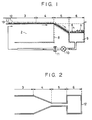
- Fig. 1 shows, in a sectional view, an example of the construction of a monomolecular film forming apparatus which may be used in the present invention.
- the apparatus has a water tank 2 containing a certain amount of water. A portion of the surface of the water within the tank 2 defines a region 12, upon which a material for forming a monomolecular film 1 is spread from a film-forming spreader 13. Another portion of the surface of the water defines a transfer region 3 for transferring part of the monomolecular film 1 on the water surface onto a substrate (not shown).
- the water tank 2 shown in Fig. 1 has a main section 8 corresponding to the transfer region 3, and a storage section 9 corresponding to the storage region 6. A part of the water which is flown into the storage section 9 is returned to the main section 8 through a return passage extending through a pump 10 and a filter 11. A heat exchanger (not shown) or the like may be disposed in the return passage so as to control the temperature of the water within the water tank 2. Since a part of the water within the tank 2 is inevitably removed when collapsed film remainders 7, described later, are removed, the water within the tank 2 has to be supplemented as required whenever such is necessary.
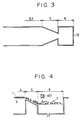
- the inclined region 5 may have a width which is not constant but gradually narrows with increases in the distance from the previous region.
- the depth of the water tank 2 may be suitably varied between a plurality of sections of the tank 2 in order to adjust the flow rate of the flow of the molecular film remainders.
- the flow of water within the inclined region 5 is accelerated in the above-described manner.
- the force of the accelerated flow of water causes the monomolecular film remainders which have been sent to the inclined region 5 to collapse (thus, when the remainders of the monomolecular film reach the storage region 6, they include pieces of the film in which the monomolecular state of the film is collapsed).
- the collapse of the monomolecular film remainders results in the area (a part of the water surface) occupied by the collapsed film remainders 7 being greatly reduced.
- the flow rate of the flow of water is preferably adjusted to a range from 5 to 10 cm/sec.
- the inclined region 5 has a narrower width than the transfer region 3, the region 5 may have the same width as the region 3.
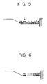
- a monomolecular film forming apparatus has a transfer region 5 and a storage region 6. It is important that the storage region (first region) be located at a sufficient distance from the region where a material for forming the monomolecular film is spread onto the water surface (second region) to prevent contact with the second region; the second region be located with respect to the region where part of the monomolecular film is transferred to a substrate (third region) so that the monomolecular film is transmitted to the third region; and the water level of the storage (first) region is lower than the water level of the transfer (third) region.
- the apparatus includes a film material supplier 802, and a transfer region 3 with respect to which a substrate 801 is vertically moved.
- Collapsed film remainders 7 are generated as described above, and stored in the storage region 6. Since the storage region 6 has a water level lower than that of the transfer region 3, the collapsed film remainders 7 are prevented from diffusing backward toward the transfer region 3.
- a paddle wheel mechanism 803 controls the film transport from the inclined area to the collapse area.
- the collapsed film remainders 7 stored in the region 6 are removed from the water surface by sucking them with an aspirator 402 or the like.
- the collapsed film remainders are removed with an aspirator 402 or the like after the remainders 7 have been mechanically compacted with a plate member 401. Such compacting may be repeated as necessary during film formation.
- Figure 8B alternatively, includes a plurality of barriers 804 for controlling the film transport from the inclined area to the collapse area.
- LB film formation was performed employing an LB film forming apparatus of the type shown in Figs. 1 and 2.
- the main section 8 of the water tank 2 of the apparatus had an area of 150 cm x 80 cm. Pure water at 20°C was contained in the water tank 2, and 22-tricosenoic acid (hereinafter abbreviated to "22-TCA”) was used as the film material.
- 22-TCA 22-tricosenoic acid
- the surface pressure was increased to 30 mN/m, thereby obtaining a 22-TCA monomolecular film 1 on the water surface.
- parts of the 22-TCA monomolecular film were successively deposited onto a silicon (Si) substrate (with a 3-inch diameter) which had a surface previously subjected to a hydrophobic property treatment using hexamethyldisilazane, and which was vertically moved at a speed of 10 mm/sec.
- the present invention has the following advantages:
Landscapes
- Engineering & Computer Science (AREA)
- Chemical & Material Sciences (AREA)
- Nanotechnology (AREA)
- Crystallography & Structural Chemistry (AREA)
- Condensed Matter Physics & Semiconductors (AREA)
- General Physics & Mathematics (AREA)
- Physics & Mathematics (AREA)
- Materials Engineering (AREA)
- Composite Materials (AREA)
- Manufacturing & Machinery (AREA)
- Application Of Or Painting With Fluid Materials (AREA)
- Coating Apparatus (AREA)
- Physical Or Chemical Processes And Apparatus (AREA)
Claims (6)
- Verfahren zum Herstellen eines monomolekularen Films oder eines monomolekularen Aufbaufilms durch Ausbreiten eines Materials zur Bildung eines monomolekularen Films auf einer Wasseroberfläche, durch Komprimieren des Materials auf der Wasseroberfläche, um dadurch das Material zu einem monomolekularen Film auszubilden und durch Transferieren des monomolekularen Films auf der Wasseroberfläche auf ein Substrat, umfassend die Schritte:- Bereitstellen eines Haupttanks (2) mit einer Ausbreitzone (12) zum Ausbreiten des zum Bilden eines monomolekularen Films vorgesehenen Materials, mit einer Transferzone (3) zum Transferieren des monomolekularen Films auf ein Substrat, und mit einer Durchsatzeinstellzone (4) zum Steuern des Strömungsdurchsatzes der Reste des monomolekularen Films, gekennzeichnet durch- Bereitstellen eines Speichertanks (9) zum Speichern der Reste des monomolekularen Films, die nicht auf das Substrat transferiert worden sind, wobei die Auftragzone (12), die Transferzone (3), die Durchsatzeinstellzone (4) und der Speichertank (9) in dieser Reihenfolge vorgesehen sind;- Speichern von Wasser in dem Haupttank (2) und dem Speichertank (9), wobei der Wasserpegel des Haupttanks (2) höher liegt als derjenige des Speichertanks (9);- Bewegen des zur Bildung des monomolekularen Films vorgesehenen Materials, welches von der Ausbreitzone (12) auf der Wasseroberfläche über die Transferzone (3) zu der Durchsatzeinstellzone (4) ausgebreitet wurde, indem auf der Wasseroberfläche eine Wasser- oder Luftströmung erzeugt wird;- Transferieren des monomolekularen Films auf das Substrat, indem das Substrat in das Wasser innerhalb der Transferzone (3) eingetaucht wird;- Bewegen der Reste des monomolekularen Films, die nicht auf das Substrat transferiert wurden, zu dem Speichertank (9); und- Entfernen des Rests des Films aus der Speicherzone.
- Verfahren zum Bilden eines monomolekularen Films oder eines monomolekularen Aufbaufilms gemäß Anspruch 1, bei dem der monomolekulare Film durch eine geneigte Zone (5) hindurchewegt wird, die zwischen der Durchsatzeinstellzone (4) und dem Speichertank (9) vorgesehen ist, und zwar im Schritt (c).
- Vorrichtung zum Bilden eines monomolekularen Films oder eines monomolekularen Aufbaufilms durch Ausbreiten eines einen monomolekularen Film bildenden Materials auf einer Wasseroberfläche, durch Komprimieren des Materials auf der Wasseroberfläche, um dadurch das Material in einen monomolekularen Film zu transformieren, und Transferieren des monomolekularen Films auf ein Substrat, umfassend:- einen Haupttank (2) mit einer Ausbreitzone (12) zum Ausbreiten des zur Bildung des monomolekularen Films vorgesehenen Materials, mit einer Transferzone (3, 8) zum Transferieren des monomolekularen Films (1) auf ein Substrat, und mit einer Durchsatzeinstellzone (4) zum Steuern des Strömungsdurchsatzes der Reste des monomolekularen Films, gekennzeichnet durch- einen Speichertank (6, 9) zum Speichern der Reste des monomolekularen Films (1), die nicht auf das Substrat übertragen wurden, wobei die Ausbreitzone (12), die Transferzone (3), die Durchsatzeinstellzone (4) und der Speichertank (9) in dieser Reihenfolge vorgesehen sind, und wobei der Wasserstand des Haupttanks (2) höher liegt als der des Speichertanks (9), wenn Wasser in dem Haupttank (2) und dem Speichertank (9) aufgenommen sind;- eine Wasser- oder Luftstrom-Erzeugungseinrichtung, um zu veranlassen, daß sich das zur Bildung des monomolekularen Films vorgesehene Material aus der Ausbreitzone (12) über die Transferzone (3) und die Durchsatzeinstellzone (4) zu dem Speichertank (9) hin bewegt; und- eine Einrichtung (402) zum Entfernen der Reste des monomolekularen Films, die nicht auf das Substrat übertragen wurden, sondern in dem Speichertank (9) gespeichert sind.
- Vorrichtung zum Bilden eines monomolekularen Films oder eines monomolekularen Aufbaufilms nach Anspruch 3, bei der eine geneigte Zone (5) zwischen der Durchsatzeinstellzone (4) und dem Speichertank (6, 9) vorgesehen ist.
- Vorrichtung zum Bilden eines monomolekularen Films oder eines monomolekularen Aufbaufilms nach Anspruch 3, bei der ein Schaufelrad (803) stromab bezüglich des Substrats (801) in der Transferzone (3) vorgesehen ist.
- Vorrichtung zum Bilden eines monomolekularen Films oder eines monomolekularen Aufbaufilms nach Anspruch 3, bei der die Breite der Durchsatzeinstellzone (4) mit zunehmendem Abstand von der Transferzone (3) allmählich geringer wird.
Applications Claiming Priority (2)
| Application Number | Priority Date | Filing Date | Title |
|---|---|---|---|
| JP3140115A JPH04367720A (ja) | 1991-06-12 | 1991-06-12 | 単分子膜又は単分子累積膜の形成方法及び形成装置 |
| JP140115/91 | 1991-06-12 |
Publications (2)
| Publication Number | Publication Date |
|---|---|
| EP0518366A1 EP0518366A1 (de) | 1992-12-16 |
| EP0518366B1 true EP0518366B1 (de) | 1996-04-03 |
Family
ID=15261265
Family Applications (1)
| Application Number | Title | Priority Date | Filing Date |
|---|---|---|---|
| EP92109936A Expired - Lifetime EP0518366B1 (de) | 1991-06-12 | 1992-06-12 | Verfahren und Vorrichtung zur Herstellung von LANGMUIR-BLODGETT-Filmen |
Country Status (5)
| Country | Link |
|---|---|
| US (1) | US5512326A (de) |
| EP (1) | EP0518366B1 (de) |
| JP (1) | JPH04367720A (de) |
| AT (1) | ATE136235T1 (de) |
| DE (1) | DE69209565T2 (de) |
Families Citing this family (11)
| Publication number | Priority date | Publication date | Assignee | Title |
|---|---|---|---|---|
| JP3262472B2 (ja) * | 1994-04-22 | 2002-03-04 | キヤノン株式会社 | ラングミュアーブロジェット膜の製造装置 |
| US5613180A (en) * | 1994-09-30 | 1997-03-18 | Keystone Investment Corporation | High density ferrous power metal alloy |
| EP0881000B8 (de) * | 1997-05-30 | 2003-03-12 | Canon Kabushiki Kaisha | Vorrichtung zur Herstellung Langmuir-Blodgett-Filmen |
| US6068878A (en) | 1998-09-03 | 2000-05-30 | Micron Technology, Inc. | Methods of forming layers of particulates on substrates |
| US7241341B2 (en) * | 2002-05-10 | 2007-07-10 | Nanometrix Inc. | Method and apparatus for two dimensional assembly of particles |
| CA2385911A1 (en) * | 2002-05-10 | 2003-11-10 | Nanometrix Inc. | Method and apparatus for two dimensional assembly of particles |
| WO2008006211A1 (en) * | 2006-07-12 | 2008-01-17 | Nanometrix Inc. | Method and apparatus for thin film/layer fabrication and deposition |
| FR2977810A1 (fr) * | 2011-07-13 | 2013-01-18 | Commissariat Energie Atomique | Installation et procede pour le depot d'un film de particules ordonnees, de largeur reglable, sur un substrat en defilement |
| WO2016033674A1 (ru) * | 2014-09-02 | 2016-03-10 | Владимир Яковлевич ШИРИПОВ | Устройство для получения наноструктурированных покрытий на твердой поверхности |
| US20170028433A1 (en) * | 2015-07-31 | 2017-02-02 | Northwestern University | Method and system for langmuir-blodgett assembly |
| US11513071B2 (en) * | 2019-10-15 | 2022-11-29 | 2Witech Solutions Llc | Sensing device for detecting analyte containing non-metallic element, and method thereof |
Family Cites Families (6)
| Publication number | Priority date | Publication date | Assignee | Title |
|---|---|---|---|---|
| GB422925A (en) * | 1933-07-21 | 1935-01-21 | India Rubber Gutta Percha Tele | Improvements in or relating to a method of and apparatus for applying variegated or "jazz" colourings to the surfaces of articles |
| FR2341199A1 (fr) * | 1976-02-11 | 1977-09-09 | Commissariat Energie Atomique | Procede et dispositif de formation et de depot sur un substrat de couches monomoleculaires de molecules amphiphiles |
| JPS60193530A (ja) * | 1984-03-14 | 1985-10-02 | Canon Inc | 成膜装置 |
| US4840821A (en) * | 1985-05-27 | 1989-06-20 | Canon Kabushiki Kaisha | Method of and apparatus for forming film |
| US4722856A (en) * | 1986-01-02 | 1988-02-02 | Molecular Electronics Corporation | Method and apparatus for depositing monomolecular layers on a substrate |
| US5143745A (en) * | 1991-08-16 | 1992-09-01 | Maganas Thomas C | Intermittent film deposition method and system |
-
1991
- 1991-06-12 JP JP3140115A patent/JPH04367720A/ja active Pending
-
1992
- 1992-06-12 DE DE69209565T patent/DE69209565T2/de not_active Expired - Fee Related
- 1992-06-12 AT AT92109936T patent/ATE136235T1/de not_active IP Right Cessation
- 1992-06-12 EP EP92109936A patent/EP0518366B1/de not_active Expired - Lifetime
-
1994
- 1994-02-23 US US08/200,317 patent/US5512326A/en not_active Expired - Lifetime
Also Published As
| Publication number | Publication date |
|---|---|
| DE69209565D1 (de) | 1996-05-09 |
| EP0518366A1 (de) | 1992-12-16 |
| US5512326A (en) | 1996-04-30 |
| ATE136235T1 (de) | 1996-04-15 |
| DE69209565T2 (de) | 1996-11-21 |
| JPH04367720A (ja) | 1992-12-21 |
Similar Documents
| Publication | Publication Date | Title |
|---|---|---|
| EP0518366B1 (de) | Verfahren und Vorrichtung zur Herstellung von LANGMUIR-BLODGETT-Filmen | |
| US7270533B2 (en) | System for creating a turbulent flow of fluid between a mold and a substrate | |
| US8211214B2 (en) | Single phase fluid imprint lithography method | |
| US7473090B2 (en) | Imprint lithography template to facilitate control of liquid movement | |
| US6613148B1 (en) | Method and apparatus for applying highly viscous liquid to substrate | |
| EP0252923B1 (de) | Verfahren und vorrichtung zum anbringen monomolekularer schichten auf ein substrat | |
| DE69720644T2 (de) | Reinigungsvorrichtung für Vakuumleitung in einer Substrat-Bearbeitungsvorrichtung | |
| US5011518A (en) | Permselective membrane and process for producing the same | |
| US20060177532A1 (en) | Imprint lithography method to control extrusion of a liquid from a desired region on a substrate | |
| US4715929A (en) | Pattern forming method | |
| US7052618B2 (en) | Nanostructures and methods of making the same | |
| EP0678345B1 (de) | Vorrichtung zur Herstellung Langmuir-Blodgett-Filmen | |
| CN1652881A (zh) | 二维粒子聚集的方法和设备 | |
| JP4024532B2 (ja) | 微粒子配列膜形成方法 | |
| JPH0661160A (ja) | パターン形成方法 | |
| US20060279018A1 (en) | Method for large-area patterning dissolved polymers by making use of an active stamp | |
| EP0824275A3 (de) | Verfahren zur Herstellung einer mehrschichtigen Struktur mit einer supraleitenden Oxyddünnschicht | |
| Deckman et al. | Microfabricated TEM sections of amorphous superlattices | |
| JP3688742B2 (ja) | 化学的気相成長装置排ガス処理装置 | |
| JPS62277147A (ja) | 薄膜の製法 | |
| SG47183A1 (en) | Method and apparatus for forming bumps on substrates | |
| JPS60225636A (ja) | 成膜方法 | |
| JPH0665757A (ja) | ガス・デポジション法による微粒子膜の形成法およびその形成装置 | |
| JPH067737A (ja) | 累積膜の連続製造方法 | |
| JPS6227077A (ja) | 固体状単分子膜形成方法 |
Legal Events
| Date | Code | Title | Description |
|---|---|---|---|
| PUAI | Public reference made under article 153(3) epc to a published international application that has entered the european phase |
Free format text: ORIGINAL CODE: 0009012 |
|
| AK | Designated contracting states |
Kind code of ref document: A1 Designated state(s): AT BE CH DE DK ES FR GB GR IT LI LU NL PT SE |
|
| 17P | Request for examination filed |
Effective date: 19930506 |
|
| 17Q | First examination report despatched |
Effective date: 19940802 |
|
| GRAA | (expected) grant |
Free format text: ORIGINAL CODE: 0009210 |
|
| AK | Designated contracting states |
Kind code of ref document: B1 Designated state(s): AT BE CH DE DK ES FR GB GR IT LI LU NL PT SE |
|
| PG25 | Lapsed in a contracting state [announced via postgrant information from national office to epo] |
Ref country code: IT Free format text: LAPSE BECAUSE OF FAILURE TO SUBMIT A TRANSLATION OF THE DESCRIPTION OR TO PAY THE FEE WITHIN THE PRE;WARNING: LAPSES OF ITALIAN PATENTS WITH EFFECTIVE DATE BEFORE 2007 MAY HAVE OCCURRED AT ANY TIME BEFORE 2007. THE CORRECT EFFECTIVE DATE MAY BE DIFFERENT FROM THE ONE RECORDED.SCRIBED TIME-LIMIT Effective date: 19960403 Ref country code: ES Free format text: THE PATENT HAS BEEN ANNULLED BY A DECISION OF A NATIONAL AUTHORITY Effective date: 19960403 Ref country code: NL Free format text: LAPSE BECAUSE OF FAILURE TO SUBMIT A TRANSLATION OF THE DESCRIPTION OR TO PAY THE FEE WITHIN THE PRESCRIBED TIME-LIMIT Effective date: 19960403 Ref country code: DK Effective date: 19960403 Ref country code: BE Effective date: 19960403 Ref country code: CH Free format text: LAPSE BECAUSE OF FAILURE TO SUBMIT A TRANSLATION OF THE DESCRIPTION OR TO PAY THE FEE WITHIN THE PRESCRIBED TIME-LIMIT Effective date: 19960403 Ref country code: AT Effective date: 19960403 Ref country code: LI Free format text: LAPSE BECAUSE OF FAILURE TO SUBMIT A TRANSLATION OF THE DESCRIPTION OR TO PAY THE FEE WITHIN THE PRESCRIBED TIME-LIMIT Effective date: 19960403 Ref country code: GR Free format text: LAPSE BECAUSE OF FAILURE TO SUBMIT A TRANSLATION OF THE DESCRIPTION OR TO PAY THE FEE WITHIN THE PRESCRIBED TIME-LIMIT Effective date: 19960403 |
|
| REF | Corresponds to: |
Ref document number: 136235 Country of ref document: AT Date of ref document: 19960415 Kind code of ref document: T |
|
| REF | Corresponds to: |
Ref document number: 69209565 Country of ref document: DE Date of ref document: 19960509 |
|
| ET | Fr: translation filed | ||
| PG25 | Lapsed in a contracting state [announced via postgrant information from national office to epo] |
Ref country code: LU Free format text: LAPSE BECAUSE OF NON-PAYMENT OF DUE FEES Effective date: 19960630 |
|
| PG25 | Lapsed in a contracting state [announced via postgrant information from national office to epo] |
Ref country code: PT Effective date: 19960703 Ref country code: SE Effective date: 19960703 |
|
| GRAH | Despatch of communication of intention to grant a patent |
Free format text: ORIGINAL CODE: EPIDOS IGRA |
|
| NLV1 | Nl: lapsed or annulled due to failure to fulfill the requirements of art. 29p and 29m of the patents act | ||
| REG | Reference to a national code |
Ref country code: CH Ref legal event code: PL |
|
| PLBE | No opposition filed within time limit |
Free format text: ORIGINAL CODE: 0009261 |
|
| STAA | Information on the status of an ep patent application or granted ep patent |
Free format text: STATUS: NO OPPOSITION FILED WITHIN TIME LIMIT |
|
| 26N | No opposition filed | ||
| REG | Reference to a national code |
Ref country code: GB Ref legal event code: IF02 |
|
| PGFP | Annual fee paid to national office [announced via postgrant information from national office to epo] |
Ref country code: GB Payment date: 20090626 Year of fee payment: 18 Ref country code: DE Payment date: 20090630 Year of fee payment: 18 |
|
| GBPC | Gb: european patent ceased through non-payment of renewal fee |
Effective date: 20100612 |
|
| REG | Reference to a national code |
Ref country code: FR Ref legal event code: ST Effective date: 20110228 |
|
| PG25 | Lapsed in a contracting state [announced via postgrant information from national office to epo] |
Ref country code: DE Free format text: LAPSE BECAUSE OF NON-PAYMENT OF DUE FEES Effective date: 20110101 |
|
| PG25 | Lapsed in a contracting state [announced via postgrant information from national office to epo] |
Ref country code: FR Free format text: LAPSE BECAUSE OF NON-PAYMENT OF DUE FEES Effective date: 20100630 |
|
| PG25 | Lapsed in a contracting state [announced via postgrant information from national office to epo] |
Ref country code: GB Free format text: LAPSE BECAUSE OF NON-PAYMENT OF DUE FEES Effective date: 20100612 |
|
| PGFP | Annual fee paid to national office [announced via postgrant information from national office to epo] |
Ref country code: FR Payment date: 20090624 Year of fee payment: 18 |