EP0517651B1 - Fabrikationsanlage - Google Patents
Fabrikationsanlage Download PDFInfo
- Publication number
- EP0517651B1 EP0517651B1 EP92810366A EP92810366A EP0517651B1 EP 0517651 B1 EP0517651 B1 EP 0517651B1 EP 92810366 A EP92810366 A EP 92810366A EP 92810366 A EP92810366 A EP 92810366A EP 0517651 B1 EP0517651 B1 EP 0517651B1
- Authority
- EP
- European Patent Office
- Prior art keywords
- rotary
- conveying
- magazine
- station
- rotary shelving
- Prior art date
- Legal status (The legal status is an assumption and is not a legal conclusion. Google has not performed a legal analysis and makes no representation as to the accuracy of the status listed.)
- Expired - Lifetime
Links
- 238000004519 manufacturing process Methods 0.000 title claims abstract description 56
- 238000009434 installation Methods 0.000 title claims 14
- 230000008878 coupling Effects 0.000 claims description 21
- 238000010168 coupling process Methods 0.000 claims description 21
- 238000005859 coupling reaction Methods 0.000 claims description 21
- 230000000284 resting effect Effects 0.000 claims description 2
- 238000003754 machining Methods 0.000 claims 2
- 239000000872 buffer Substances 0.000 description 5
- 239000000463 material Substances 0.000 description 3
- 230000006698 induction Effects 0.000 description 2
- 230000015654 memory Effects 0.000 description 2
- 240000002834 Paulownia tomentosa Species 0.000 description 1
- 235000010678 Paulownia tomentosa Nutrition 0.000 description 1
- 240000000528 Ricinus communis Species 0.000 description 1
- 235000004443 Ricinus communis Nutrition 0.000 description 1
- 230000008901 benefit Effects 0.000 description 1
- 230000008859 change Effects 0.000 description 1
- 238000010276 construction Methods 0.000 description 1
- 238000006073 displacement reaction Methods 0.000 description 1
- 230000000694 effects Effects 0.000 description 1
- 230000006870 function Effects 0.000 description 1
- 230000007774 longterm Effects 0.000 description 1
- 238000000034 method Methods 0.000 description 1
- 230000008569 process Effects 0.000 description 1
- 239000013589 supplement Substances 0.000 description 1
Images


Classifications
-
- B—PERFORMING OPERATIONS; TRANSPORTING
- B23—MACHINE TOOLS; METAL-WORKING NOT OTHERWISE PROVIDED FOR
- B23Q—DETAILS, COMPONENTS, OR ACCESSORIES FOR MACHINE TOOLS, e.g. ARRANGEMENTS FOR COPYING OR CONTROLLING; MACHINE TOOLS IN GENERAL CHARACTERISED BY THE CONSTRUCTION OF PARTICULAR DETAILS OR COMPONENTS; COMBINATIONS OR ASSOCIATIONS OF METAL-WORKING MACHINES, NOT DIRECTED TO A PARTICULAR RESULT
- B23Q7/00—Arrangements for handling work specially combined with or arranged in, or specially adapted for use in connection with, machine tools, e.g. for conveying, loading, positioning, discharging, sorting
- B23Q7/14—Arrangements for handling work specially combined with or arranged in, or specially adapted for use in connection with, machine tools, e.g. for conveying, loading, positioning, discharging, sorting co-ordinated in production lines
-
- B—PERFORMING OPERATIONS; TRANSPORTING
- B23—MACHINE TOOLS; METAL-WORKING NOT OTHERWISE PROVIDED FOR
- B23Q—DETAILS, COMPONENTS, OR ACCESSORIES FOR MACHINE TOOLS, e.g. ARRANGEMENTS FOR COPYING OR CONTROLLING; MACHINE TOOLS IN GENERAL CHARACTERISED BY THE CONSTRUCTION OF PARTICULAR DETAILS OR COMPONENTS; COMBINATIONS OR ASSOCIATIONS OF METAL-WORKING MACHINES, NOT DIRECTED TO A PARTICULAR RESULT
- B23Q3/00—Devices holding, supporting, or positioning work or tools, of a kind normally removable from the machine
- B23Q3/155—Arrangements for automatic insertion or removal of tools, e.g. combined with manual handling
- B23Q3/1552—Arrangements for automatic insertion or removal of tools, e.g. combined with manual handling parts of devices for automatically inserting or removing tools
- B23Q3/15526—Storage devices; Drive mechanisms therefor
- B23Q3/15539—Plural magazines, e.g. involving tool transfer from one magazine to another
-
- B—PERFORMING OPERATIONS; TRANSPORTING
- B23—MACHINE TOOLS; METAL-WORKING NOT OTHERWISE PROVIDED FOR
- B23Q—DETAILS, COMPONENTS, OR ACCESSORIES FOR MACHINE TOOLS, e.g. ARRANGEMENTS FOR COPYING OR CONTROLLING; MACHINE TOOLS IN GENERAL CHARACTERISED BY THE CONSTRUCTION OF PARTICULAR DETAILS OR COMPONENTS; COMBINATIONS OR ASSOCIATIONS OF METAL-WORKING MACHINES, NOT DIRECTED TO A PARTICULAR RESULT
- B23Q7/00—Arrangements for handling work specially combined with or arranged in, or specially adapted for use in connection with, machine tools, e.g. for conveying, loading, positioning, discharging, sorting
- B23Q7/10—Arrangements for handling work specially combined with or arranged in, or specially adapted for use in connection with, machine tools, e.g. for conveying, loading, positioning, discharging, sorting by means of magazines
-
- B—PERFORMING OPERATIONS; TRANSPORTING
- B23—MACHINE TOOLS; METAL-WORKING NOT OTHERWISE PROVIDED FOR
- B23Q—DETAILS, COMPONENTS, OR ACCESSORIES FOR MACHINE TOOLS, e.g. ARRANGEMENTS FOR COPYING OR CONTROLLING; MACHINE TOOLS IN GENERAL CHARACTERISED BY THE CONSTRUCTION OF PARTICULAR DETAILS OR COMPONENTS; COMBINATIONS OR ASSOCIATIONS OF METAL-WORKING MACHINES, NOT DIRECTED TO A PARTICULAR RESULT
- B23Q7/00—Arrangements for handling work specially combined with or arranged in, or specially adapted for use in connection with, machine tools, e.g. for conveying, loading, positioning, discharging, sorting
- B23Q7/14—Arrangements for handling work specially combined with or arranged in, or specially adapted for use in connection with, machine tools, e.g. for conveying, loading, positioning, discharging, sorting co-ordinated in production lines
- B23Q7/1426—Arrangements for handling work specially combined with or arranged in, or specially adapted for use in connection with, machine tools, e.g. for conveying, loading, positioning, discharging, sorting co-ordinated in production lines with work holders not rigidly fixed to the transport devices
-
- Y—GENERAL TAGGING OF NEW TECHNOLOGICAL DEVELOPMENTS; GENERAL TAGGING OF CROSS-SECTIONAL TECHNOLOGIES SPANNING OVER SEVERAL SECTIONS OF THE IPC; TECHNICAL SUBJECTS COVERED BY FORMER USPC CROSS-REFERENCE ART COLLECTIONS [XRACs] AND DIGESTS
- Y02—TECHNOLOGIES OR APPLICATIONS FOR MITIGATION OR ADAPTATION AGAINST CLIMATE CHANGE
- Y02P—CLIMATE CHANGE MITIGATION TECHNOLOGIES IN THE PRODUCTION OR PROCESSING OF GOODS
- Y02P90/00—Enabling technologies with a potential contribution to greenhouse gas [GHG] emissions mitigation
- Y02P90/02—Total factory control, e.g. smart factories, flexible manufacturing systems [FMS] or integrated manufacturing systems [IMS]
-
- Y—GENERAL TAGGING OF NEW TECHNOLOGICAL DEVELOPMENTS; GENERAL TAGGING OF CROSS-SECTIONAL TECHNOLOGIES SPANNING OVER SEVERAL SECTIONS OF THE IPC; TECHNICAL SUBJECTS COVERED BY FORMER USPC CROSS-REFERENCE ART COLLECTIONS [XRACs] AND DIGESTS
- Y10—TECHNICAL SUBJECTS COVERED BY FORMER USPC
- Y10T—TECHNICAL SUBJECTS COVERED BY FORMER US CLASSIFICATION
- Y10T409/00—Gear cutting, milling, or planing
- Y10T409/30—Milling
- Y10T409/30448—Milling with detachable or auxiliary cutter support to convert cutting action
-
- Y—GENERAL TAGGING OF NEW TECHNOLOGICAL DEVELOPMENTS; GENERAL TAGGING OF CROSS-SECTIONAL TECHNOLOGIES SPANNING OVER SEVERAL SECTIONS OF THE IPC; TECHNICAL SUBJECTS COVERED BY FORMER USPC CROSS-REFERENCE ART COLLECTIONS [XRACs] AND DIGESTS
- Y10—TECHNICAL SUBJECTS COVERED BY FORMER USPC
- Y10T—TECHNICAL SUBJECTS COVERED BY FORMER US CLASSIFICATION
- Y10T409/00—Gear cutting, milling, or planing
- Y10T409/30—Milling
- Y10T409/309296—Detachable or repositionable tool head
-
- Y—GENERAL TAGGING OF NEW TECHNOLOGICAL DEVELOPMENTS; GENERAL TAGGING OF CROSS-SECTIONAL TECHNOLOGIES SPANNING OVER SEVERAL SECTIONS OF THE IPC; TECHNICAL SUBJECTS COVERED BY FORMER USPC CROSS-REFERENCE ART COLLECTIONS [XRACs] AND DIGESTS
- Y10—TECHNICAL SUBJECTS COVERED BY FORMER USPC
- Y10T—TECHNICAL SUBJECTS COVERED BY FORMER US CLASSIFICATION
- Y10T483/00—Tool changing
- Y10T483/10—Process
-
- Y—GENERAL TAGGING OF NEW TECHNOLOGICAL DEVELOPMENTS; GENERAL TAGGING OF CROSS-SECTIONAL TECHNOLOGIES SPANNING OVER SEVERAL SECTIONS OF THE IPC; TECHNICAL SUBJECTS COVERED BY FORMER USPC CROSS-REFERENCE ART COLLECTIONS [XRACs] AND DIGESTS
- Y10—TECHNICAL SUBJECTS COVERED BY FORMER USPC
- Y10T—TECHNICAL SUBJECTS COVERED BY FORMER US CLASSIFICATION
- Y10T483/00—Tool changing
- Y10T483/11—Tool changing with safety means
- Y10T483/115—Guard
-
- Y—GENERAL TAGGING OF NEW TECHNOLOGICAL DEVELOPMENTS; GENERAL TAGGING OF CROSS-SECTIONAL TECHNOLOGIES SPANNING OVER SEVERAL SECTIONS OF THE IPC; TECHNICAL SUBJECTS COVERED BY FORMER USPC CROSS-REFERENCE ART COLLECTIONS [XRACs] AND DIGESTS
- Y10—TECHNICAL SUBJECTS COVERED BY FORMER USPC
- Y10T—TECHNICAL SUBJECTS COVERED BY FORMER US CLASSIFICATION
- Y10T483/00—Tool changing
- Y10T483/17—Tool changing including machine tool or component
- Y10T483/1733—Rotary spindle machine tool [e.g., milling machine, boring, machine, grinding machine, etc.]
- Y10T483/1736—Tool having specific mounting or work treating feature
- Y10T483/1738—Tool head
-
- Y—GENERAL TAGGING OF NEW TECHNOLOGICAL DEVELOPMENTS; GENERAL TAGGING OF CROSS-SECTIONAL TECHNOLOGIES SPANNING OVER SEVERAL SECTIONS OF THE IPC; TECHNICAL SUBJECTS COVERED BY FORMER USPC CROSS-REFERENCE ART COLLECTIONS [XRACs] AND DIGESTS
- Y10—TECHNICAL SUBJECTS COVERED BY FORMER USPC
- Y10T—TECHNICAL SUBJECTS COVERED BY FORMER US CLASSIFICATION
- Y10T483/00—Tool changing
- Y10T483/17—Tool changing including machine tool or component
- Y10T483/1733—Rotary spindle machine tool [e.g., milling machine, boring, machine, grinding machine, etc.]
- Y10T483/179—Direct tool exchange between spindle and matrix
- Y10T483/1793—Spindle comprises tool changer
Definitions
- the invention relates to a manufacturing system with at least one manufacturing cell, which has at least one processing device, a magazine station assigned to the manufacturing cell with a plurality of transport units designed as transportable units Rotary shelves for receiving tools and / or workpieces and a handling device for operating the magazine station, wherein each rotating shelf has several storage levels arranged around one another around a rotating column and a support plate in the lower column area and can be exchanged for a stationary one, the means for operating a rotating shelf Containing part of the magazine station can be used, further with a transfer station separate from the manufacturing cell for loading and unloading the rotating shelves and at least one industrial truck for transporting the rotating shelves from the transfer station to the magazine station and vice versa.
- a manufacturing plant of this type is e.g. known from JP-A-59 146 727.
- a magazine station is described therein, which is located in the vicinity of a machine tool and is intended to supplement or replace the tool supply of the machine tool as required.
- This magazine station is set up to accommodate several transportable rotary shelves and to bring them individually into the access area of a handling device assigned to the magazine station, which in turn can take tools from a selected rotary shelf and feed them to the machine's own tool magazine, and vice versa.
- this magazine station has a rotatable support frame and a lifting drive device on a stationary base.
- Each rotating shelf can be placed on the support frame with a support plate arranged in the lower column area and in a specific rotational angle position of the support frame with a column shaft located below the support plate can be coupled to the drive device.
- the carrier plate has no function in the operation of the rotating shelves and when transporting them.
- the magazine station described forms an additional intermediate station.
- a conveyor device which is intended for transferring a pallet for tools or workpieces from a rail vehicle to a processing device and vice versa.
- This conveyor is located on the rail vehicle and has a coupling device to which the pallet for the respective transfer is coupled. No magazine assigned to the processing device is provided for the pallets.
- the invention aims to improve a manufacturing plant of the type mentioned by changing the concept in terms of material handling and to simplify the auxiliary devices.
- the transfer of the rotating shelves from the magazine station to the industrial truck and from this to the transfer station and vice versa should be facilitated and, if need be, be automated.
- the magazine station is arranged in the immediate vicinity of a handling device intended for automatic tool or workpiece change on the processing device and has a receiving space on the stationary part for an exchangeable rotating shelf, that the rotating shelves at the lower end the column has a base plate that forms the drive and transport base, that on the industrial truck and in the transfer station, pick-up locations are set up for each rotating shelf, the relevant base locations on the base plate of the rotary shelves being effective holding means for transporting or handling the rotary shelves in the Have reloading station, and that at the receiving station of the magazine station and at the receiving stations of the industrial truck and the reloading station each have a conveyor with a horizontal conveyor track for the transfer from there in an upright position en rotating shelves from the magazine station to the industrial truck and from this to the transfer station and vice versa is provided, the conveyor tracks of all conveying devices having the same level and the conveying devices working together in pairs during a transfer.
- the interchangeable magazine can be replaced periodically or as required with new workpieces or tools and unloaded and reloaded outside the magazine station.
- the magazine exchange can take place without interrupting the ongoing manufacturing process.
- the latter can be operationally linked to one another by leading the path of the means of transport past all the manufacturing cells and forwarding the magazines loaded with the corresponding objects from the manufacturing cell to the manufacturing cell with the aid of the means of transportation.
- a bogie and a lifting device for relocating a rotating shelf from the conveying device to the bogie and vice versa advantageously include the establishment of a receiving place of the transfer station.
- the arrangement can be such that a rotating shelf placed on the bogie with the foot plate can be freely rotated so that it can be easily and conveniently loaded and unloaded manually.
- the bogie can have a set of castors arranged in a circle and a specific axle pin to be engaged in a centering sleeve on the rotary shelf foot plate, the roller set and the axle pin being individually vertically displaceable by the lifting device.
- the various conveying devices preferably contain aids which ensure that the rotary shelves reach or maintain the desired position at the respective stations.
- the practical design of the magazine station consists, for example, according to a proposal disclosed in EP-A-0 517 652, in that it has a frame on which releasable coupling means for storage and for the cooperation with the two ends of the rotatable column of the rotating shelf Drive of the rotating shelf are attached.
- a preferred embodiment of the magazine is characterized in that the rotatable column of the rotary shelf has a foot plate forming the drive and transport base at its lower end, and further in that the rotatable column of the rotary shelf has a downwardly open centering sleeve on the foot plate and on its upper one End has a centering cone that in the lower part of the frame there is a driven turntable, provided with an upwardly directed centering pin, on which the rotating shelf is placed, the base plate of the rotary shelf resting on the base plate and its centering pin engaging in the centering sleeve of the base plate that on the top of the frame a shaft stub with a downwardly open conical centering hole for receiving the centering cone of the column is freely rotatable, and that the turntable including the rotary drive is mounted on a lifting table, which pushes the rotary rack used upwards moves so that the column between the turntable and the stub shaft is held positively and in the correct position and the foot plate is frictionally connected to the turntable
- the arrangement is preferably such that the rotary rack can be lowered from the operating position with the foot plate onto the conveyor track and the coupling means when released release it from the rotary shelf for movement in the conveying direction.
- the means for converting the rotating shelf from the operating position into the transport position are designed, for example, in such a way that the lifting table can be lowered from the operating position to such an extent that the centering pin on the turntable, after the rotating shelf has been placed on the conveyor, disengages from the centering sleeve at the lower end of the column and that the stub shaft can be pulled upwards to disengage the centering cone at the top of the column from the center hole on the stub shaft so that the rotating rack can be released from the coupling means in two phases, with the rotating rack below in the first phase Continuation of the upper coupling means with its foot plate is placed on the conveyor and the lower coupling means are released and in the subsequent second phase the upper coupling means are released from the rotary shelf.
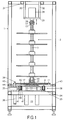
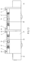
- the magazine chosen as an exemplary embodiment with an exchangeable rotary shelf according to FIGS. 1 to 9 has at the magazine station a frame, generally designated 1, made up of square tubes, which has a square outline and has a height corresponding to the rotary shelf 2 shown separately in FIG. 4 and which bears the stationary part of the magazine which contains the means for rotary operation.
- the individual parts of this frame 1 are referred to in the course of the description as needed.
- the rotating shelf generally designated 2 essentially consists in a manner known per se of a rotatable column 3, on which the carrier 4 of the objects to be handled (workpieces and / or tools) in the form of round disks in several planes with uniform Height distances are fixed.
- the specimen slides 4 are each provided with a hub 5, which in a manner not shown, e.g. through pinning, is anchored to pillar 3.
- each slide 4 has on its circumference a number (e.g. eight) of storage spaces 6 of identical design, which are characterized, for example, by a radial incision 7 and axial recesses 8 for the correct positioning of objects with a uniform holder.
- the rotatable column 3 of the rotary shelf 2 has at its lower end a foot plate 9 which forms the drive and transport base and which can be anchored to the column 3 in a manner similar to the specimen slides 4 with a hub 10.
- This foot plate 9 has a somewhat larger diameter than the specimen slides 4 and is close to its circumference with a number (For example, eight) locking holes 11 are provided, which serve to position the rotating shelf 2 in different rotational positions.
- the hub 10 located at the lower end of the column 3 also forms a centering sleeve 12 which is open at the bottom, and at its upper end the column 3 has a centering cone 13.
- Coupling means mounted on the frame 1 are provided for the storage and the drive of the rotary rack 2, which cooperate with the ends of the column 3 designed in the manner described.
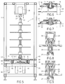
- a turntable 14 on which the rotary shelf 2 rests with its foot adjuster 9 according to FIGS. 1 and 2 in the operating position. Details of this turntable 14 can be seen in FIGS. 6 and 7.
- a friction lining 15 is applied to the latter.
- the turntable 14 sits on a shaft 16 and is rotatably mounted with it on a lifting table 17 in the manner shown.
- the turntable 14 To drive the turntable 14, it is provided on its periphery with a toothing 18 into which a pinion 19 of an electric drive motor 20 which engages on the lifting table 17 engages.
- the upper end of the shaft 16 forms an upwardly projecting centering pin 21 which engages in the centering sleeve 12 on the foot plate 9 of the rotary shelf 2 placed thereon (FIG. 1).
- four working cylinders 22 are provided, which can be acted upon with a pressure medium are and the piston rods 23 are connected to the lifting table 17.
- the working cylinders 22 are mounted on the underside of a base plate 24, which in turn rests on a frame part 25 of the frame 1.
- the upper coupling means consist of a rotatable and vertically displaceable shaft end 26, which is provided with a conical centering bore 27 which is open at the bottom for receiving the centering cone 13 of the column 3 of the rotary rack 2.
- the stub shaft 26 is mounted in a drive block 28, which rests on a platform 29, which in turn is anchored to the upper frame part 31 of the frame 1 with support plates 30.
- the drive block 28 is a schematically represented working cylinder with a pressurized piston 32, the stub shaft 26 being freely rotatably mounted in the hollow piston rod 33.
- the lifting table 17 is under the force of the working cylinders 22 in an upper end position (FIGS. 1, 2 and 6), and the pressurized working cylinder 28 presses the shaft end 26 against the upper end 13 of the column in the opposite direction of force 3.
- the centering pin 21 on the turntable 14 is in engagement with the centering sleeve 12 at the lower end of the column 3 and the centering cone 13 at the upper end of the column 3 is in engagement with the conical centering bore 27 of the Stub shaft 26, so that the column 3 between the turntable 14 and the stub shaft 26 is held in a form-fitting manner and in the correct position and the foot plate 9 is connected to the turntable 14 by friction.
- a vertically movable locking pin 34 is provided in a known manner, which works together with the locking holes 11 in the foot plate 9 of the rotating shelf 2 and through one with the frame 1 a support arm 35 connected working cylinder 36 can be actuated (Fig. 1).
- an electronic storage device 37 on the edge of the foot adjuster 9 which contains, among other things, data for identifying the rotary shelf used, which can be read by a reading device 38 mounted on the frame 1 (FIG. 2).
- a conveyor device 39 with a horizontal conveyor track is provided on the stationary part of the magazine, on which the rotating shelf 2 can be lowered. It is a roller conveyor arranged on the base plate 24, the rollers 40 of which are mounted in plane-parallel support plates 41 and are driven by chains 42 by a common drive motor, not shown.
- the conveyor track are 9 effective guide rails 43 for the longitudinal guidance of the rotating shelf on the circumference of the foot adjuster 2 available, which guide rails 43 are attached to a frame part 44 of the frame 1 (Fig. 1 and 3).
- An end stop 45 is also attached to the same frame part 44 (FIGS.
- a rotary shelf 2 is removed from the magazine in such a way that first the rotary shelf 2 is lowered from the operating position shown in FIGS. 1 to 3 into the transport position shown in FIG. 5, ie onto the conveyor device 39.
- the lifting table 17 can be lowered so far that the centering pin 21 on the turntable 14 comes out of engagement with the centering sleeve 12 at the lower end of the column 3 after the foot plate 9 has been placed on the rollers 40.
- the working cylinder 28 remains under pressure, so that the guiding effect at the upper end of the column is maintained during the lowering movement of the rotary rack 2.
- the stub shaft 26 is then pulled up by counterpressure in the working cylinder 28 in order to disengage the centering cone 13 at the upper column end from the centering bore 27 in the stub shaft 26.
- the rotary rack 2 is thus released from the lower and upper coupling means, the end position of which can be seen from FIGS. 7 and 9, and can be moved by the conveyor device 39 on the front side of the frame 1 shown in FIG. 1, as soon as the locking pin 34 has been withdrawn downward from the previously occupied locking hole 11 in the foot plate 9.
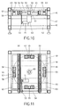
- a frame 46 consisting of square tubes with a square outline is used to build up the receiving space of the transfer station, the height of which corresponds approximately to the lower part of the magazine frame 1 (FIG. 1) closed by the frame part 44.
- a base plate 48 rests on a central frame part 47 of the frame 46 and carries a conveyor device 49 with a horizontal conveyor plane formed by two roller sets 50.
- the conveying device 49 is essentially of the same design as the conveying device 39 of the magazine, the horizontal conveying path of which has the same level as that of the conveying device 39.
- the drive of the conveying device 49 is also shown in the drawing, namely a drive motor 51 is provided , which is attached to a lower frame part 52 of the frame 46 and drives a common drive shaft 54 of the two roller sets 50 via a chain drive 53.
- the bogie comprises a set of four rollers 55 arranged in a circle, on which the foot plate 56 of the Dreg shelf indicated by dash-dotted lines comes to rest.
- Each roller 55 is freely rotatably supported in a bearing block 57, on which two lifting cylinders 58 supported on the base plate 48 act, which are actuated together to raise the roller 55 from the level of the conveying plane or lower it onto the same.
- the bogie also includes a specific axle 60 to engage in the centering sleeve 59 of the foot actuator 56, which is guided in a bearing bush 61 arranged above the base plate 48 and can be actuated by a lifting cylinder 62 arranged below the base plate 48.
- the lifting cylinder 58 on the one hand and the lifting cylinder 62 on the other hand can be controlled separately so that the rollers 55 and the journal 60 can be displaced vertically at different times.
- This option is used primarily when relocating a rotating rack from the conveyor 49 to the bogie by first lifting the axle 60 to center the rotating rack and only then the rotating rack by the rollers 55 of the bogie from the roller sets 50 of the conveyor 49 is lifted off.
- the rotary shelf placed here is guided into the centering area in that along the conveyor track of the conveyor device 49 effective guide rails 63 are provided on the circumference of the foot plate 55 and an end stop 64 is provided at the end of the conveyor track.
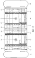
- a truck is schematically shown for the most part, as it is primarily used in automatically operated transport systems.
- the means for the remote-controlled operation of such industrial trucks are known per se and are not explained in more detail here.
- the entire substructure of the vehicle including the chassis is designated 65.
- Buffers 66 are also provided in a known manner at both ends of the vehicle substructure 65.
- the superstructure of the vehicle includes two receiving places for a rotating shelf each, the foot plate 67 is indicated by dash-dotted lines.
- a conveyor device 68 with a horizontal conveyor track of the type already described is in turn provided at each receiving location, the conveyor tracks here also having the same level as those in the magazine station and in the transfer station. Details of these conveyors can be found in the description of FIGS. 10 and 11.
- the reception areas are set up here so that the vehicle can be loaded and unloaded from both sides.
- the guide rails 69 acting on the circumference of the foot plates 67 extend over the entire length of the conveyor track or over the entire width of the vehicle.
- axle journals 70 are intended to engage in the centering sleeve of the rotary shelf attached and thereby secure the rotary shelf against lateral displacement, while the retaining strips 71 prevent the rotary shelf from tipping over.
- FIG. 14 schematically shows, as an example of a simple manufacturing system, the spatial arrangement of a processing device 75, a handling device 76 and a magazine 77 with an exchangeable rotary shelf 2 according to the construction shown in FIGS. 1 to 9 and the symbolically indicated tools or Workpieces 78.
- the handling device 76 is equipped with three controlled axes and has a gripping arm 79 which is mounted in a bearing part 80 so as to be longitudinally displaceable.
- the bearing part 80 is rotatably mounted on a carriage 81 about the axis 82, which in turn is mounted on a stationary column 83 so as to be vertically displaceable.
- the various phases of movement of the gripper arm 79 when changing the tool or workpiece are indicated by dash-dotted lines.
- FIG. 14 also shows an industrial truck 84, which is designed, for example, according to FIGS. 12 and 13 and is guided in a manner known per se along the course of an induction loop 85 close to the magazine station 77. 14, the vehicle 84 is in a first stopping position in which its free receiving space 86 lies exactly opposite the magazine station, so that the rotating shelf 2 to be exchanged can be transferred from the magazine station 77 to the vehicle 84 with the support of the relevant conveying devices 87 and 88 .
- the rotary rack 90 intended for the replacement of the rotary rack 2, which contains the tools or workpieces 91 required to continue the manufacturing process, is located at the second receiving location 89.
- the occupied recording space is aligned with the magazine station 77 in order to transfer the new rotating shelf 90 to the space in the magazine station 77 which has meanwhile become vacant.
- the replacement of the rotating shelves 2 and 90 can be carried out fully automatically in this way with the aid of appropriate control devices.
- FIG. 15 schematically shows a manufacturing system which has several, for example three manufacturing cells 100, each with two processing devices 101, two handling devices 102 assigned to them individually and a common magazine 103 for the handling objects, furthermore a transfer station 104 with, for example, four receiving places 105 and a buffer store 106 with a plurality of receiving spaces 107 for interchangeable rotating shelves.
- Automatically operated and guided industrial trucks 108 of the type described, each with two receiving spaces 109, are used to transport the rotating shelves between the transfer station 104, the buffer store 106 and the production cells.
- industrial trucks with more than two receiving locations can also be provided.
- the roadway of the vehicles 108 determined by induction loops 110 leads along the production cells 100, so that the production cells are directly connected to one another in terms of traffic and the rotary shelves with the tools or workpieces stored therein, directly from a production cell, in accordance with the sequence of different work processes can be passed on to the next production cell.
- the production cells 100 can of course also be connected in a star shape to the transfer station 104 or to the buffer store 106.
Landscapes
- Engineering & Computer Science (AREA)
- Mechanical Engineering (AREA)
- Warehouses Or Storage Devices (AREA)
- Multi-Process Working Machines And Systems (AREA)
- Organic Low-Molecular-Weight Compounds And Preparation Thereof (AREA)
- Catalysts (AREA)
- Glass Compositions (AREA)
- Window Of Vehicle (AREA)
- Finger-Pressure Massage (AREA)
- Mechanical Treatment Of Semiconductor (AREA)
- General Factory Administration (AREA)
Description
- In den EP 0132599 A1 und EP 0297034 A2 sind Fabrikationsanlagen beschrieben, die Magazinstationen mit fest stationierten Drehregalen aufweisen, welche auch unter der Bezeichnung "Mehrebenen-Rundtaktspeicher" bekannt sind. Für den mannlosen, zeitlich ausgedehnten Betrieb einer solchen Fabrikationsanlage ist unter Umständen, insbesondere bei schnell wechselnden Fertigungsaufgaben, eine grosse Zahl von Werkstücken und Werkzeugen bereitzustellen, wozu verhältnismässig grosse Magazinräume und entsprechend weiträumig arbeitende Handhabungsgeräte zur Verfügung stehen müssen. Nach dem Stand der Technik sind zur Bedienung einer oder mehrerer Bearbeitungsmaschinen für diesen Fall oft mehrere Mehrebenen-Rundtaktspeicher und z.B. ein Portalroboter als Handhabungsgerät erforderlich, wie beispielsweise aus dem Aufsatz "Möglichkeiten und Trends bei der automatischen Werkstückhandhabung mit Industrierobotern" in der Zeitschrift "wt-Z.ind.Fertig.76(1986)Nr.10, S. 585-589 (Springer-Verlag)" hervorgeht. Der Materialaufwand und der Platzbedarf für die in einem solchen Umfang erforderlichen Hilfseinrichtungen sind erfahrungsgemäss beträchtlich. Ferner dauert der Betriebsunterbruch für die am Magazinstandort vorgenommene Erneuerung des Magazinbestandes dem Umfang des Magazinraumes entsprechend lang.
- Die Erfindung betrifft demgegenüber eine Fabrikationsanlage mit wenigstens einer Fertigungszelle, welche wenigstens eine Bearbeitungseinrichtung, eine der Fertigungszelle zugeordnete Magazinstation mit mehreren, als transportfähige Baueinheiten ausgebildeten Drehregalen zur Aufnahme von Werkzeugen und/oder Werkstücken und ein Handhabungsgerät zur Bedienung der Magazinstation umfasst, wobei jedes Drehregal mehrere, rund um eine drehbare Säule übereinander angeordnete Lagerebenen und im unteren Säulenbereich einen Auflageteller aufweist und austauschbar in einen stationären, die Mittel zum Betrieb eines Drehregals enthaltenden Teil der Magazinstation einsetzbar ist, ferner mit einer von der Fertigungszelle getrennten Umladestation zum Beladen und Entladen der Drehregale und wenigstens einem Flurförderfahrzeug für den Transport der Drehregale von der Umladestation zur Magazinstation und umgekehrt.
- Eine Fabrikationsanlage dieser Art ist z.B. aus der Patentschrift JP-A-59 146 727 bekannt. Darin ist eine Magazinstation beschrieben, welche sich in der Nähe einer Werkzeugmaschine befindet und dazu bestimmt ist, den Werkzeugvorrat der Werkzeugmaschine nach Bedarf zu ergänzen bzw. auszutauschen. Diese Magazinstation ist dafür eingerichtet, mehrere transportable Drehregale aufzunehmen und diese einzeln in den Zugriffsbereich eines der Magazinstation zugeordneten Handhabungsgerätes zu bringen, welches seinerseits einem ausgewählten Drehregal Werkzeuge entnehmen und dem maschineneigenen Werkzeugmagazin zuführen kann, und umgekehrt.
- Zu diesem Zweck weist diese Magazinstation an einem stationären Untersatz ein drehbares Traggestell sowie eine anhebbare Antriebsvorrichtung auf. Jedes Drehregal ist mit einem im unteren Säulenbereich angeordneten Auflageteller auf das Traggestell aufsetzbar und in einer bestimmten Drehwinkellage des Traggestells mit einem unterhalb des Tragtellers befindlichen Säulenschaft an die Antriebsvorrichtung ankuppelbar. Im Betrieb der Drehregale und beim Transports derselben hat der Tragteller keine Funktion. Die beschriebene Magazinstation bildet eine zusätzliche Zwischenstation.
- Aus der Patentschrift US-A-4 597 709 ist ferner eine Fördereinrichtung bekannt, welche zur Übergabe einer Palette für Werkzeuge oder Werkstücke von einem Schienenfahrzeug an eine Bearbeitungseinrichtung, und umgekehrt, bestimmt ist. Diese Fördereinrichtung befindet sich auf dem Schienenfahrzeug und besitzt eine Kupplungseinrichtung, an welche die Palette für den jeweiligen Transfer angekuppelt wird. Für die Paletten ist kein der Bearbeitungseinrichtung zugeordnetes Magazin vorgesehen.
- Der Erfindung bezweckt, eine Fabrikationsanlage der genannten Art durch eine Änderung des Konzepts in bezug auf den Materialumschlag zu verbessern und hinsichtlich der Hilfseinrichtungen zu vereinfachen. Dabei soll der Transfer der Drehregale von der Magazinstation zum Flurförderfahrzeug und von diesem zur Umladestation und umgekehrt erleichtert werden und allenfalls automatisierbar sein.
- Die Lösung dieser Aufgabe besteht gemäss der Erfindung darin, dass die Magazinstation in unmittelbarer Reichweite eines für den automatischen Werkzeug- bzw. Werkstückwechsel an der Bearbeitungseinrichtung bestimmten Handhabungsgerätes angeordnet ist und am stationären Teil einen Aufnahmeplatz für ein austauschbares Drehregal aufweist, dass die Drehregale am unteren Ende der Säule einen die Antriebs- und Transportbasis bildenden Fussteller aufweisen, dass auf dem Flurförderfahrzeug und in der Umladestation Aufnahmeplätze für je ein Drehregal eingerichtet sind, wobei die betreffenden Aufnahmeplätze am Fussteller der Drehregale wirksame Halterungsmittel für den Transport bzw. für die Handhabung der Drehregale in der Umladestation aufweisen, und dass am Aufnahmeplatz der Magazinstation und an den Aufnahmeplätzen des Flurförderfahrzeugs und der Umladestation je eine Fördereinrichtung mit horizontaler Förderbahn für den Transfer von in aufrechter Stellung darauf abgestellten Drehregalen von der Magazinstation zum Flurförderfahrzeug und von diesem zur Umladestation und umgekehrt vorgesehen ist, wobei die Förderbahnen aller Fördereinrichtungen das gleiche Niveau haben und die Fördereinrichtungen bei einem Transfer jeweils paarweise zusammenarbeiten.
- Auf diese Weise ist es möglich, an der Magazinstation ein kleineres Speichervolumen und für die Bedienung der Bearbeitungsmaschinen ein einfacheres Handhabungsgerät vorzusehen. Dadurch lässt sich auch die Zugriffszeit zum Magazin verkürzen. Das auswechselbare Magazin kann periodisch bzw. nach Bedarf durch solches mit neuen Werkstücken bzw. Werkzeugen ersetzt und ausserhalb der Magazinstation entladen und neu beladen werden. Dabei kann der Magazinaustausch ohne Unterbrechung des laufenden Fabrikationsvorgangs stattfinden. In einer Fabrikationsanlage mit mehreren Fertigungszellen lassen sich die letzteren betriebsmässig miteinander verknüpfen, indem die Bahn der Transportmittel an allen Fertigungszellen vorbeiführt und die mit den entsprechenden Objekten beladenen Magazine mit Hilfe der Transportmittel von Fertigungszelle zu Fertigungszelle weitergeleitet werden.
- Zur Einrichtung eines Aufnahmeplatzes der Umladestation gehören mit Vorteil ein Drehgestell und eine Hubeinrichtung zum Umlagern eines Drehregals von der Fördereinrichtung auf das Drehgestell und umgekehrt. Dabei kann die Anordnung so getroffen sein, dass ein mit dem Fussteller auf das Drehgestell aufgesetztes Drehregal frei drehbar ist, damit es einfach und bequem manuell beladen und entladen werden kann. Das Drehgestell kann zu diesem Zweck einen Satz im Kreis angeordneter Laufrollen und einen in eine Zentriermuffe am Drehregal-Fussteller einzugreifen bestimmten Achszapfen aufweisen, wobei der Laufrollensatz und der Achszapfen durch die Hubeinrichtung einzeln vertikal verschiebbar sind. Im übrigen enthalten die verschiedenen Fördereinrichtungen vorzugsweise Hilfsmittel, welche gewährleisten, dass die Drehregale an den jeweiligen Stationen die gewünschte Position erreichen bzw. beibehalten. So sind beispielsweise längs der Förderbahn aller Fördereinrichtungen am Umfang des Fusstellers wirksame Führungsschienen für die Längsführung des Drehregals vorhanden. Ferner kann die Förderbahn der Fördereinrichtungen, welche der Magazinstation und der Umladestation zugeordnet sind, einen Endanschlag aufweisen, welcher das auflaufende Drehregal im Wirkungsbereich der jeweiligen Halterungsmittel stillsetzt. Schliesslich können längs der Förderbahn der dem Flurförderfahrzeug zugeordneten Fördereinrichtung den Fussteller des aufgesetzten Drehregals übergreifende Halteleisten vorgesehen sein, welche ein Kippen des Drehregals verhindern.
- Die praktische Ausführung der Magazinstation besteht z.B., gemäss einem in der EP-A-0 517 652 offenbarten Vorschlag, darin, dass diese ein Gestell aufweist, an dem lösbare, mit den beiden Enden der drehbaren Säule des Drehregals zusammenarbeitende Kupplungsmittel für die Lagerung und den Antrieb des Drehregals angebracht sind.
- Eine bevorzugte Ausführungsform des Magazins ist dadurch gekennzeichnet, dass die drehbare Säule des Drehregals an ihrem unteren Ende einen die Antriebs- und Transportbasis bildenden Fussteller aufweist, und ferner dadurch, dass die drehbare Säule des Drehregals am Fussteller eine nach unten offene Zentriermuffe und an ihrem oberen Ende einen Zentrierkonus aufweist, dass sich im unteren Teil des Gestells ein angetriebener, mit einem nach oben gerichteten Zentrierzapfen versehener Drehschemel befindet, auf den das Drehregal aufgesetzt ist, wobei der Fussteller des Drehregals auf dem Drehschemel ruht und dessen Zentrierzapfen in die Zentriermuffe des Fusstellers eingreift, dass an der Oberseite des Gestells ein Wellenstumpf mit nach unten offener konischer Zentrierbohrung für die Aufnahme des Zentrierkonus der Säule frei drehbar gelagert ist, und dass der Drehschemel samt Drehantrieb an einem Hubtisch gelagert ist, welcher das eingesetzte Drehregal unter Krafteinwirkung nach oben drückt, so dass dessen Säule zwischen dem Drehschemel und dem Wellenstumpf formschlüssig und positionsgerecht gehalten und der Fussteller mit dem Drehschemel reibschlüssig verbunden ist.
- Dabei ist die Anordnung vorzugsweise so getroffen, dass das Drehregal aus der Betriebslage mit dem Fussteller auf die Förderbahn absenkbar ist und die Kupplungsmittel beim Lösen vom Drehregal dieses für eine Bewegung in Förderrichtung freigeben.
- Die Mittel für die Umsetzung des Drehregals aus der Betriebslage in die Transportlage sind beispielsweise so gestaltet, dass der Hubtisch aus der Betriebslage so weit absenkbar ist, dass der Zentrierzapfen am Drehschemel nach dem Aufsetzen des Drehregals auf die Fördereinrichtung mit der Zentriermuffe am unteren Säulenende ausser Eingriff kommt, und dass der Wellenstumpf nach oben wegziehbar ist, um den Zentrierkonus am oberen Säulenende mit der Zentriebohrung am Wellenstumpof ausser Eingriff zu bringen, so dass die Lösung des Drehregals von den Kupplungsmitteln in zwei Phasen erfolgen kann, wobei in der ersten Phase das Drehregal unter Fortwirkung der oberen Kupplungsmittel mit seinem Fussteller auf die Fördereinrichtung aufgesetzt wird und die unteren Kupplungsmittel gelöst werden und in der anschliessenden zweiten Phase die oberen Kupplungsmittel vom Drehregal gelöst werden.
- In der Zeichnung sind Ausführungsbeispiele der Erfindung dargestellt, und zwar zeigen:
- Fig. 1
- Frontansicht eines Magazins mit austauschbarem Drehregal;
- Fig. 2
- Seitenansicht des Magazins;
- Fig. 3
- Grundriss des Magazins;
- Fig. 4
- Seitenansicht des austauschbaren, als transportfähi ge Baueinheit ausgebildeten Drehregals;
- Fig. 5
- Frontansicht nach Fig. 1, mit auf die Fördereinrich tung abgesenktem und von den Kupplungsmitteln frei gegebenem Drehregal;
- Fig. 6
- Schnittansicht der unteren Kupplungsmittel in grösserem Massstab, im Betriebszustand;
- Fig. 7
- Schnittansicht gemäss Fig. 6, Kupplungsmittel im ge lösten Zustand;
- Fig. 8
- Schnittansicht der oberen Kupplungsmittel in grösse rem Massstab, im Betriebszustand;
- Fig. 9
- Schnittansicht gemäss Fig. 8, Kupplungsmittel im ge lösten Zustand;
- Fig. 10
- Frontansicht eines Aufnahmeplatzes an der Umlade station;
- Fig. 11
- Grundriss des Aufnahmeplatzes nach Fig. 10;
- Fig. 12
- Grundriss eines Flurförderfahrzeugs mit zwei Aufnahmeplätzen für je ein Drehregal
- Fig. 13
- Seitenansicht des Flurförderfahrzeugs nach Fig. 12;
- Fig. 14
- Schematische Darstellung einer Fertigungszelle mit einer Bearbeitungsmaschine, einer Magazinstation und einem Handhabungsgerät, sowie eines Flurförderfahrzeugs;
- Fig. 15
- Schematische Darstellung einer Fabrikationsanlage mit mehreren Fertigungszellen, mehreren Flurförderfahrzeugen, einer Umladestation und einem Pufferlager.
- Das als Ausführungsbeispiel gewählte Magazin mit austauschbarem Drehregal nach den Fig. 1 bis 9 besitzt an der Magazinstation ein gesamthaft mit 1 bezeichnetes, aus Vierkantrohren aufgebautes Gestell, welches einen quadratischen Grundriss und eine dem in Fig. 4 separat dargestellten Drehregal 2 entsprechende Höhe aufweist und welches den stationären, die Mittel für den Rundtaktbetrieb enthaltenden Teil des Magazins trägt. Die einzelnen Teile dieses Gestells 1 werden im Verlauf der Beschreibung nach Bedarf näher bezeichnet.
- Gemäss Fig. 4 besteht das gesamthaft mit 2 bezeichnete Drehregal in an sich bekannter Weise im wesentlichen aus einer drehbaren Säule 3, an welcher die Träger 4 der zu handhabenden Objekte (Werkstücke und/oder Werkzeuge) in Form von runden Scheiben in mehreren Ebenen mit gleichmässigen Höhenabständen befestigt sind. Die Objektträger 4 sind zu diesem Zweck mit je einer Nabe 5 versehen, welche in nicht näher dargestellter Weise, z.B. durch Verstiftung, an der Säule 3 verankert ist. Gemäss Fig. 3 verfügt jeder Objektträger 4 an seinem Umfang über eine Anzahl (z.B. acht) unter sich gleich ausgebildeter Lagerplätze 6, welche beispielsweise durch einen radialen Einschnitt 7 und achsiale Vertiefungen 8 für eine positionsgerechte Plazierung von Objekten mit einheitlicher Halterung gekennzeichnet sind.
- Die drehbare Säule 3 des Drehregals 2 weist an ihrem unteren Ende einen die Antriebs- und Transportbasis bildenden Fussteller 9 auf, welcher in ähnlicher Weise wie die Objektträger 4 mit einer Nabe 10 an der Säule 3 verankert sein kann. Dieser Fussteller 9 hat einen etwas grösseren Durchmesser als die Objektträger 4 und ist nahe seines Umfangs mit einer Anzahl (z.B. acht) Rastlöchern 11 versehen, welche zur Positionierung des Drehregals 2 in verschiedenen Drehlagen dienen. Die am unteren Ende der Säule 3 befindliche Nabe 10 bildet zugleich eine nach unten offene Zentriermuffe 12, und an ihrem oberen Ende weist die Säule 3 einen Zentrierkonus 13 auf.
- Für die Lagerung und den Antrieb des Drehregals 2 sind am Gestell 1 montierte Kupplungsmittel vorgesehen, welche mit den in der beschriebenen Weise ausgebildeten Enden der Säule 3 zusammenarbeiten. Im unteren Teil des Gestells 1 befindet sich ein Drehschemel 14, auf dem das Drehregal 2 in der Betriebslage mit seinem Fussteller 9 gemäss den Fig. 1 und 2 aufliegt. Einzelheiten dieses Drehschemels 14 gehen aus den Fig. 6 und 7 hervor. Zur reibschlüssigen Verbindung zwischen Drehregal 2 und Drehschemel 14 ist auf den letzteren ein Reibbelag 15 aufgebracht. Der Drehschemel 14 sitzt auf einer Welle 16 und ist mit dieser an einem Hubtisch 17 in der dargestellten Weise drehbar gelagert. Zum Antrieb des Drehschemels 14 ist dieser an seinem Umfang mit einer Verzahnung 18 versehen, in welche ein Ritzel 19 eines elektrischen Antriebsmotors 20 eingreift, der am Hubtisch 17 befestigt ist. Das obere Ende der Welle 16 bildet einen nach oben ragenden Zentrierzapfen 21, welcher in die Zentriermuffe 12 am Fussteller 9 des aufgesetzten Drehregals 2 eingreift (Fig. 1). Für die Höhenverstellung des Hubtisches 17 sind vier Arbeitszylinder 22 vorgesehen, welche mit einem Druckmedium beaufschlagbar sind und deren Kolbenstangen 23 mit dem Hubtisch 17 verbunden sind. Die Arbeitszylinder 22 sind an der Unterseite einer Grundplatte 24 montiert, welche ihrerseits auf einem Rahmenteil 25 des Gestells 1 ruht.
- Die oberen Kupplungsmittel bestehen gemäss Fig. 1 aus einem drehbaren und vertikal verschiebbaren Wellenstumpf 26, welcher mit einer nach unten offenen konischen Zentrierbohrung 27 zur Aufnahme des Zentrierkonus 13 der Säule 3 des Drehregals 2 versehen ist. Der Wellenstumpf 26 ist in einem Antriebsblock 28 gelagert, welcher auf einer Plattform 29 ruht, die ihrerseits mit Stützplatten 30 an einem oberen Rahmenteil 31 des Gestells 1 verankert ist. Wie aus den Fig. 8 und 9 im einzelnen hervorgeht, handelt es sich bei dem Antriebsblock 28 um einen schematisch dargestellten Arbeitszylinder mit einem druckbeaufschlagten Kolben 32, wobei der Wellenstumpf 26 in der hohlen Kolbenstange 33 frei drehbar gelagert ist.
- Im Betriebszustand des Magazins befindet sich der Hubtisch 17 unter der Krafteinwirkung der Arbeitszylinder 22 in einer oberen Endstellung (Fig. 1, 2 und 6), und der unter Druck stehende Arbeitszylinder 28 drückt den Wellenstumpf 26 mit entgegengesetzter Kraftrichtung gegen das obere Ende 13 der Säule 3. Dabei befindet sich der Zentrierzapfen 21 am Drehschemel 14 im Eingriff mit der Zentriermuffe 12 am unteren Ende der Säule 3 und der Zentrierkonus 13 am oberen Ende der Säule 3 im Eingriff mit der konischen Zentrierbohrung 27 des Wellenstumpfes 26, so dass die Säule 3 zwischen dem Drehschemel 14 und dem Wellenstumpf 26 formschlüssig und positionsgerecht gehalten und der Fussteller 9 mit dem Drehschemel 14 reibschlüssig verbunden ist.
- Zum Fixieren des Drehregals 2 in den für die Entnahme der Lagerobjekte durch das Handhabungsgerät vorgesehenen Winkelstellungen ist in an sich bekannter Weise ein vertikal beweglicher Raststift 34 vorgesehen, welcher mit den Rastlöchern 11 im Fussteller 9 des Drehregals 2 zusammenarbeitet und durch einen mit dem Gestell 1 über einen Tragarm 35 verbundenen Arbeitszylinder 36 betätigbar ist (Fig. 1). Ausserdem befindet sich am Rande des Fusstellers 9 eine elektronische Speichereinrichtung 37, welche unter anderem Daten zur Identifikation des eingesetzten Drehregals enthält, die durch eine am Gestell 1 montierte Leseeinrichtung 38 abgelesen werden können (Fig. 2).
- Für den Austausch des Drehregals 2 ist am stationären Teil des Magazins eine Fördereinrichtung 39 mit horizontaler Förderbahn vorgesehen, auf welche das Drehregal 2 absenkbar ist. Es handelt sich dabei um einen auf der Grundplatte 24 angeordneten Rollenförderer, dessen Rollen 40 in planparallelen Stützplatten 41 gelagert und über Ketten 42 durch einen gemeinsamen, nicht dargestellten Antriebsmotor angetrieben werden. Längs der Förderbahn sind am Umfang des Fusstellers 9 wirksame Führungsschienen 43 für die Längsführung des Drehregals 2 vorhanden, welche Führungsschienen 43 an einem Rahmenteil 44 des Gestells 1 befestigt sind (Fig. 1 und 3). Am gleichen Rahmenteil 44 ist auch ein Endanschlag 45 angebracht (Fig. 2 und 3), an welchem der Fussteller 9 anstösst, wenn ein Drehregal 2 auf der Fördereinrichtung 39 in das Gestell 1 eingefahren wird, so dass das Drehregal 2 im Zentrierbereich stillgesetzt wird, damit der Zentrierzapfen 21 in die Zentriermuffe 12 und der Zentrierkonus in die konische Zentrierbohrung 27 einfahren kann.
- Die Entnahme eines Drehregals 2 aus dem Magazin geschieht in der Weise, dass zunächst das Drehregal 2 aus der in den Fig. 1 bis 3 dargestellten Betriebslage in die in Fig. 5 dargestellte Transportlage, d.h. auf die Fördereinrichtung 39 abgesenkt wird. Der Hubtisch 17 ist dabei so weit absenkbar, dass der Zentrierzapfen 21 am Drehschemel 14 nach dem Aufsetzen des Fusstellers 9 auf die Rollen 40 mit der Zentriermuffe 12 am unteren Ende der Säule 3 ausser Eingriff kommt. Der Arbeitszylinder 28 bleibt dabei noch unter Druck, so dass die Führungswirkung am oberen Säulenende während der Senkbewegung des Drehregals 2 erhalten bleibt. Danach wird der Wellenstumpf 26 durch Gegendruck im Arbeitszylinder 28 hochgezogen, um den Zentrierkonus 13 am oberen Säulenende mit der Zentrierbohrung 27 im Wellenstumpf 26 ausser Eingriff zu bringen. Damit ist das Drehregal 2 von den unteren und oberen Kupplungsmitteln gelöst, deren Endstellung aus den Fig. 7 und 9 hervorgeht, und lässt sich durch die Fördereinrichtung 39 an der in Fig. 1 dargestellten Frontseite des Gestells 1 aus diesem herausbewegen, sobald auch der Raststift 34 aus dem zuvor belegten Rastloch 11 im Fussteller 9 nach unten zurückgezogen worden ist.
- Zum Aufbau des in den Fig. 10 und 11 dargestellten Aufnahmeplatzes der Umladestation dient wiederum ein aus Vierkantrohren bestehendes Gestell 46 mit quadratischem Grundriss, das in seiner Höhe etwa dem durch den Rahmenteil 44 abgeschlossenen Unterteil des Magazingestells 1 (Fig. 1) entspricht. Auf einem mittleren Rahmenteil 47 des Gestells 46 ruht eine Grundplatte 48, welche eine Fördereinrichtung 49 mit horizontaler, durch zwei Rollensätzen 50 gebildeter Förderebene trägt. Die Fördereinrichtung 49 ist im wesentlichen gleich ausgebildet wie die Fördereinrichtung 39 des Magazins, wobei die horizontale Förderbahn derselben das gleiche Nieveau hat wie diejenige der Fördereinrichtung 39. Im vorliegenden Anwendungsfall ist auch der Antrieb der Fördereinrichtung 49 zeichnerisch dargestellt, und zwar ist ein Antriebsmotor 51 vorgesehen, welcher an einem tiefer liegenden Rahmenteil 52 des Gestells 46 befestigt ist und über einen Kettentrieb 53 eine gemeinsame Antriebswelle 54 der beiden Rollensätze 50 antreibt.
- An dem gezeigten Aufnahmeplatz der Umladestation ist auch ein Drehgestell und eine Hubeinrichtung zum Umlagern eines Drehregals von der Fördereinrichtung 49 auf das Drehgestell und umgekehrt vorhanden, damit das Drehregal zum Umladen gedreht werden kann. Das Drehgestell umfasst einen Satz von vier im Kreis angeordneter Laufrollen 55, auf welche der strichpunktiert angedeuete Fussteller 56 des Dregregals zu liegen kommt. Jede Laufrolle 55 ist in einem Lagerbock 57 frei drehbar gelagert, an welchem zwei auf der Grundplatte 48 abgestützte Hubzylinder 58 angreifen, welche gemeinsam betätigt werden, um die Laufrollen 55 vom Niveau der Förderebene anzuheben bzw. auf dasselbe abzusenken. Zum Drehgestell gehört auch ein in die Zentriermuffe 59 des Fusstellers 56 einzugreifen bestimmter Achszapfen 60, welcher in einer oberhalb der Grundplatte 48 angeordneten Lagerbüchse 61 geführt und durch einen unterhalb der Grundplatte 48 angeordneten Hubzylinder 62 betätigbar ist. Dabei sind die Hubzylinder 58 einerseits und der Hubzylinder 62 andererseits getrennt steuerbar, damit die Laufrollen 55 und der Achszapfen 60 zu verschiedenen Zeitpunkten vertikal verschiebbar sind. Diese Möglichkeit wird vor allem beim Umlagern eines Drehregals von der Fördereinrichtung 49 auf das Drehgestell benutzt, indem zunächst der Achszapfen 60 angehoben wird, um das Drehregal zu zentrieren, und erst danach das Drehregal durch die Laufrollen 55 des Drehgestells von den Rollensätzen 50 der Fördereinrichtung 49 abgehoben wird. Aehnlich wie bei der Magazinstation wird auch hier das aufgesetzte Drehregal dadurch in den Zentrierbereich geführt, dass längs der Förderbahn der Fördereinrichtung 49 am Umfang des Fusstellers 55 wirksame Führungsschienen 63 und am Ende der Förderbahn ein Endanschlag 64 vorgesehen sind.
- In den Fig. 12 und 13 ist ein Flurförderfahrzeug mehrheitlich schematisch dargestellt, wie es vornehmlich in automatisch betriebenen Transportsystemen angewandt wird. Die Mittel zum ferngesteuerten Betrieb solcher Flurförderfahrzeuge sind an sich bekannt und werden hier nicht näher erläutert. Der gesamte Unterbau des Fahrzeugs einschliesslich Fahrgestell ist mit 65 bezeichnet. An beiden Enden des Fahrzeugunterbaus 65 sind in ebenfalls bekannter Weise Puffer 66 vorgesehen.
- Der Oberbau des Fahrzeugs umfasst zwei Aufnahmeplätze für je ein Drehregal, dessen Fussteller 67 strichpunktiert angedeutet ist. An jedem Aufnahmeplatz ist wiederum eine Fördereinrichtung 68 mit horizontaler Förderbahn von der bereits beschriebenen Art vorgesehen, wobei die Förderbahnen auch hier das gleiche Niveau haben wie diejenigen in der Magazinstation und in der Umladestation. Einzelheiten dieser Fördereinrichtungen können der Beschreibung zu den Fig. 10 und 11 entnommen werden. Die Aufnahmeplätze sind hier so eingerichtet, dass das Fahrzeug von beiden Seiten her beladen und entladen werden kann. Zu diesem Zweck erstrecken sich hier die am Umfang der Fussteller 67 wirksamen Führungsschienen 69 über die ganze Länge der Förderbahn bzw. über die ganze Breite des Fahrzeugs. Zur Fixierung der auf das Fahrzeug aufgesetzten Drehregale während des Transports sind einerseits im Zentrum der Aufnahmeplätze angeordnete, in gleicher Art wie die Achszapfen 60 in den Fig. 10 und 11 vertikal bewegliche Achszapfen 70 und andererseits den Fussteller 67 übergreifende Halteleisten 71 vorgesehen. Die Achszapfen 70 sind dazu bestimmt, in die Zentriermuffe des aufgesetzten Drehregals einzugreifen und dadurch das Drehregal gegen eine seitliche Verschiebung zu sichern, während die Halteleisten 71 ein Kippen des Drehregals verhindern.
- Die Fig. 14 zeigt schematisch als Beispiel für eine einfache Fabrikationsanlage die räumliche Anordnung einer Bearbeitungseinrichtung 75, eines Handhabungsgerätes 76 und eines Magazins 77 mit austauschbarem Drehregal 2 gemäss der in den Fig. 1 bis 9 dargestellten Bauart und darin gelagerten, symbolisch andeuteten Werkzeugen bzw. Werkstücken 78. Das Handhabungsgerät 76 ist mit drei gesteuerten Achsen ausgerüstet und besitzt einen Greifarm 79, welcher in einem Lagerteil 80 längsverschieblich gelagert ist. Der Lagerteil 80 ist an einem Schlitten 81 um die Achse 82 drehbar gelagert, welcher seinerseits an einer stationären Säule 83 vertikal verschiebbar gelagert ist. Die verschiedenen Bewegungsphasen des Greifarms 79 beim Werkzeug- bzw. Werkstückwechsel sind mit strichpunktierten Linien angedeutet. Die Fig. 14 zeigt deutlich, dass die Hilfseinrichtungen verhältnismässig wenig Stationsraum beanspruchen und das Handhabungsgerät 76 nur geringen Bewegungsraum benötigt. Dieser Vorteil ergibt sich daraus, dass auch für einen länger dauernden Betrieb der Fabrikationsanlage ein einziges Magazin 77 der beschriebenen Art ausreicht und sich somit beim Materialaustausch der Zugriff des Greifarms 79 auf dieses eine Magazin 77 beschränken kann.
- Die Fig. 14 zeigt auch ein Flurförderfahrzeug 84, welches beispielsweise gemäss den Fig. 12 und 13 ausgebildet ist und in an sich bekannter Weise mit Hilfe einer Induktionsschleife 85 längs deren Verlauf nahe an die Magazinstation 77 herangeführt wird. In Fig. 14 befindet sich das Fahrzeug 84 in einer ersten Halteposition, in welcher sein freier Aufnahmeplatz 86 der Magazinstation genau gegenüberliegt, so dass das auszutauschende Drehregal 2 mit Unterstützung der betreffenden Fördereinrichtungen 87 und 88 aus der Magazinstation 77 auf das Fahrzeug 84 transferiert werden kann. An dem zweiten Aufnahmeplatz 89 befindet sich das für den Ersatz des Drehregals 2 bestimmte Drehregal 90, welches die zur Fortsetzung des Fabrikationsablaufs benötigten Werkzeuge bzw. Werkstücke 91 enthält. Durch Vorrücken des Fahrzeugs 84 wird der belegte Aufnahmeplatz auf die Magazinstation 77 ausgerichtet, um das neue Drehregal 90 an den inzwischen frei gewordenen Platz in der Magazinstation 77 zu transferieren. Der Austausch der Drehregale 2 und 90 kann auf diese Weise mit Hilfe entsprechender Steuerungseinrichtungen vollautomatisch durchgeführt werden.
- In Fig. 15 ist schematisch eine Fabrikationsanlage dargestellt, welche mehrere, z.B. drei Fertigungszellen 100 mit je zwei Bearbeitungseinrichtungen 101, zwei diesen einzeln zugeordneten Handhabungsgeräten 102 und einem gemeinsamen Magazin 103 für die Handhabungsobjekte, ferner eine Umladestation 104 mit z.B. vier Aufnahmeplätzen 105 und ein pufferlager 106 mit einer Mehrzahl von Aufnahmeplätzen 107 für austauschbare Drehregale umfasst. Für den Transport der Drehregale zwischen der Umladestation 104, dem Pufferlager 106 und den Fertigungszellen dienen automatisch betriebene und geführte Flurförderfahrzeuge 108 der beschriebenen Art mit je zwei Aufnahmeplätzen 109. Es können aber auch Flurförderfahrzeuge mit mehr als zwei Aufnahmeplätzen vorgesehen sein. Im vorliegenden Beispiel führt die durch Induktionsschleifen 110 bestimmte Fahrbahn der Fahrzeuge 108 den Fertigungszellen 100 entlang, so dass die Fertigungszellen verkehrsmässig direkt miteinander verbunden sind und die Drehregale mit den darin gelagerten Werkzeugen bzw. Werkstücken, der Reihenfolge verschiedener Arbeitsprozesse entsprechend, von einer Fertigungszelle unmittelbar zu der nächsten Fertigungszelle weitergereicht werden können. Selbstverständlich können in anderen Anwendungsfällen die Fertigungszellen 100 auch sternförmig mit der Umladestation 104 bzw. mit dem pufferlager 106 verbunden sein.
Claims (13)
- Fabrikationsanlage mit wenigstens einer Fertigungszelle (100), welche wenigstens eine Bearbeitungseinrichtung (75; 101), eine der Fertigungszelle zugeordnete Magazinstation (77; 103) mit mehreren, als transportfähige Baueinheiten ausgebildeten Drehregalen (2) zur Aufnahme von Werkzeugen und/oder Werkstücken (91) und ein Handhabungsgerät (76; 102) zur Bedienung der Magazinstation umfasst, wobei jedes Drehregal (2) mehrere, rund um eine drehbare Säule (3) übereinander angeordnete Lagerebenen (4) und im unteren Säulenbereich einen Auflageteller (9) aufweist und austauschbar in einen stationären, die Mittel zum Betrieb eines Drehregals (2) enthaltenden Teil der Magazinstation (77; 103) einsetzbar ist, ferner mit einer von der Fertigungszelle (100) getrennten Umladestation (104) zum Beladen und Entladen der Drehregale (2) und wenigstens einem Flurförderfahrzeug (84; 108) für den Transport der Drehregale (2) von der Umladestation (104) zur Magazinstation (77;103) und umgekehrt, dadurch gekennzeichnet, dass die Magazinstation (77; 103) in unmittelbarer Reichweite eines für den automatischen Werkzeug- bzw. Werkstückwechsel an der Bearbeitungseinrichtung (75, 101) bestimmten Handhabungsgerätes (76; 102) angeordnet ist und am stationären Teil einen Aufnahmeplatz für ein austauschbares Drehregal (2) aufweist, dass jeweils jedes Drehregal (2) am unteren Ende der Säule (3) einen die Antriebs- und Transportbasis bildenden Fussteller (9; 56; 67) aufweist, der gleichzeitig als Auflageteller funktioniert, dass aus dem Flurförderfahrzeug (84; 108) und in der Umladestation (104) Aufnahmeplätze (86, 89, 109; 105) für je ein Drehregal (2) eingerichtet sind, wobei die betreffenden Aufnahmeplätze am Fussteller der Drehregale wirksame Halterungsmittel (70, 71; 60) für den Transport bzw. für die Handhabung der Drehregale in der Umladestation aufweisen, und dass am Aufnahmeplatz der Magazinstation und an den Aufnahmeplätzen (86, 89, 109; 105) des Flurförderfahrzeugs (84; 108) und der Umladestation (108) je eine Fördereinrichtung (39, 68, 49) mit horizontaler Förderbahn für den Transfer von in aufrechter Stellung darauf abgestellten Drehregalen (2) von der Magazinstation (103) zum Flurförderfahrzeug (108) und von diesem zur Umladestation (104) und umgekehrt vorgesehen ist, wobei die Förderbahnen aller Fördereinrichtungen das gleiche Niveau haben und die Fördereinrichtungen bei einem Transfer jeweils paarweise zusammenarbeiten.
- Fabrikationsanlage nach Anspruch 1, dadurch gekennzeichnet, dass die Fördereinrichtungen (39, 68, 49) Rollenförderer mit gemeinsam angetriebenen Rollen sind.
- Fabrikationsanlage nach Anspruch 1, dadurch gekennzeichnet, dass die Förderbahn der Fördereinrichtungen (39, 49), welche der Magazinstation und der Umladestation zugeordnet sind, einen Endanschlag (45, 64) aufweisen, welcher das auflaufende Drehregal (2) im Wirkungsbereich der jeweiligen Halterungsmittel (21;60) stillsetzt.
- Fabrikationsanlage nach Anspruch 1, dadurch gekennzeichnet, dass längs der Förderbahn jeder Fördereinrichtung (39, 49, 68) am Umfang des Fusstellers (9; 56; 67) wirksame Führungsorgane (43; 63; 69) für die Längsführung des Drehregals (2) vorhanden sind.
- Fabrikationsanlage nach Anspruch 1, dadurch gekennzeichnet, dass längs der Förderbahn der dem Flurförderfahrzeug zugeordneten Fördereinrichtung (68) den Fussteller (67) des aufgesetzten Drehregals übergreifende Halteleisten (71) vorgesehen sind.
- Fabrikationsanlage nach Anspruch 1, dadurch gekennzeichnet, dass an jedem Aufnahmeplatz (105) der Umladestation (104) ein Drehgestell (55, 60) und eine Hubeinrichtung (58, 62) zum Umlagern eines Drehregals (2) von der Fördereinrichtung (49) auf das Drehgestell und umgekehrt vorhanden sind.
- Fabrikationsanlage nach Anspruch 6, dadurch gekennzeichnet, dass ein mit dem Fussteller (9; 56) auf das Drehgestell (55, 60) aufgesetztes Drehregal (2) frei drehbar ist.
- Fabrikationsanlage nach Anspruch 7, dadurch gekennzeichnet, dass das Drehgestell (55, 60) einen Satz im Kreis angeordneter Laufrollen (55) und einen in eine Zentriermuffe (59) am Fussteller (56) eines Drehregals (2) einzugreifen bestimmten Achszapfen (60) aufweist, wobei der Laufrollensatz und der Achszapfen durch die Hubeinrichtung (58, 62) einzeln vertikal verschiebbar sind.
- Fabrikationsanlage nach Anspruch 1, dadurch gekennzeichnet, dass die Magazinstation (77; 103) ein Gestell (1) aufweist, an dem lösbare, mit den beiden Enden der drehbaren Säule (3) des Drehregals (2) zusammenarbeitende Kupplungsmittel (14, 21; 26) für die Lagerung und den Antrieb des Drehregals (2) angebracht sind,
- Fabrikationsanlage nach Anspruch 9, dadurch gekennzeichnet, dass die drehbare Säule (3) des Drehregals (2) am Fussteller (9) eine nach unten offene Zentriermuffe (12) und an ihrem oberen Ende einen Zentrierkonus (13) aufweist, dass sich im unteren Teil des Gestells (1) ein angetriebener, mit einem nach oben gerichteten Zentrierzapfen (21) versehener Drehschemel (14) befindet, auf den das Drehgestell (2) aufgesetzt ist, wobei der Fussteller (9) des Drehregals auf dem Drehschemel (14) ruht und dessen Zentrierzapfen (21) in die Zentriermuffe (12) des Fusstellers (9) eingreift, dass an der Oberseite des Gestells (1) ein Wellenstumpf (26) mit nach unten offener konischer Zentrierbohrung (27) für die Aufnahme des Zentrierkonus (13) der Säule (3) frei drehbar gelagert ist, und dass der Drehschemel (14) samt Drehantrieb (19, 20) an einem Hubtisch (17) gelagert ist, welcher das eingesetzte Drehregal (2) unter Krafteinwirkung nach oben drückt, so dass dessen Säule (3) zwischen dem Drehschemel (14) und dem Wellenstumpf (26) formschlüssig und positionsgerecht gehalten und der Fussteller (9) mit dem Drehschemel (14) reibschlüssig verbunden ist.
- Fabrikationsanlage nach Anspruch 10, dadurch gekennzeichnet, dass das Drehregal (2) aus der Betriebslage mit dem Fussteller (9) auf die Förderbahn absenkbar ist, wobei die Kupplungsmittel (14, 21, 26) beim Lösen vom Drehregal (2) dieses für eine Bewegung in Förderrichtung freigeben.
- Fabrikationsanlage nach Anspruch 11, dadurch gekennzeichnet, dass der Hubtisch (17) aus der Betriebslage so weit absenkbar ist, dass der Zentrierzapfen (21) am Drehschemel (14) nach dem Aufsetzen des Drehregals (2) auf die Fördereinrichtung (39) mit der Zentriermuffe (12) am unteren Säulenende ausser Eingriff kommt, und dass der Wellenstumpf (26) nach oben wegziehbar ist, um den Zentrierkonus (13) am oberen Säulenende mit der Zentrierbohrung (27 am Wellenstumpf (26) ausser Eingriff zu bringen, so dass die Lösung des Drehregals (2) von den Kupplungsmitteln (14, 21, 26) in zwei Phasen erfolgen kann, wobei in der ersten Phase das Drehregal (2) unter Fortwirkung der oberen Kupplunsmittel (26) mit seinem Fussteller (9) auf die Fördereinrichtung (39) aufgesetzt wird und die unteren Kupplungsmittel (14, 21) gelöst werden und in der anschliessenden zweiten Phase die oberen Kupplungsmittel (26) vom Drehregal (2) gelöst werden.
- Fabrikationsanlage nach Anspruch 1, dadurch gekennzeichnet, dass automatisch betriebene und geführte Flurförderfahrzeuge (84; 108) und für diese Fahrzeuge Fahrbahnen (85; 110) vorgesehen sind, welche die Magazinstationen (103) verschiedener Fertigungszellen (100) untereinander und mit der Umladestation (104) verbinden.
Applications Claiming Priority (2)
| Application Number | Priority Date | Filing Date | Title |
|---|---|---|---|
| DE4118108A DE4118108A1 (de) | 1991-06-03 | 1991-06-03 | Fabrikationsanlage |
| DE4118108 | 1991-06-03 |
Publications (2)
| Publication Number | Publication Date |
|---|---|
| EP0517651A1 EP0517651A1 (de) | 1992-12-09 |
| EP0517651B1 true EP0517651B1 (de) | 1996-03-06 |
Family
ID=6433043
Family Applications (1)
| Application Number | Title | Priority Date | Filing Date |
|---|---|---|---|
| EP92810366A Expired - Lifetime EP0517651B1 (de) | 1991-06-03 | 1992-05-15 | Fabrikationsanlage |
Country Status (13)
| Country | Link |
|---|---|
| US (1) | US5242359A (de) |
| EP (1) | EP0517651B1 (de) |
| JP (1) | JPH05177516A (de) |
| KR (1) | KR100232979B1 (de) |
| AT (1) | ATE134915T1 (de) |
| CA (1) | CA2070102C (de) |
| DE (2) | DE4118108A1 (de) |
| DK (1) | DK0517651T3 (de) |
| ES (1) | ES2083719T3 (de) |
| GR (1) | GR3019887T3 (de) |
| HK (1) | HK88496A (de) |
| SG (1) | SG43116A1 (de) |
| TW (1) | TW213435B (de) |
Families Citing this family (19)
| Publication number | Priority date | Publication date | Assignee | Title |
|---|---|---|---|---|
| NL9300650A (nl) * | 1993-04-16 | 1994-11-16 | Maatman Beheer Bv Geb | Inrichting voor het opnemen van een aantal voorwerpen. |
| US5620405A (en) * | 1994-06-29 | 1997-04-15 | Matsushita Electric Industrial Co., Ltd. | Supplying method and system of component/tool and, apparatus and cassette to be used in the method |
| DE9417529U1 (de) * | 1994-11-01 | 1995-12-14 | KTW Konstruktion-Technik K. Weißhaupt GmbH, 88046 Friedrichshafen | Vorrichtung zur Magazinierung von Werkstücken |
| DE19708096A1 (de) | 1997-02-28 | 1998-09-03 | Hueller Hille Gmbh | Bearbeitungszentrum |
| US5882285A (en) * | 1997-10-03 | 1999-03-16 | Amada Mfg America, Inc. | Punching tool storing and interchanging system |
| US6478722B1 (en) * | 2000-02-18 | 2002-11-12 | The Boeing Company | C-frame assembly apparatus and method for large panel-shaped workpieces |
| US6754557B2 (en) * | 2001-09-20 | 2004-06-22 | The Tech Group | System and method for manufacturing plastic injection stack components |
| FR2863519B1 (fr) * | 2003-12-11 | 2006-01-21 | Snecma Moteurs | Dispositif de montage et de demontage automatiques d'outils sur un automate |
| JP4342928B2 (ja) * | 2003-12-25 | 2009-10-14 | 株式会社森精機製作所 | 工作機械の工具交換装置 |
| US8122580B2 (en) * | 2008-06-26 | 2012-02-28 | American Railcar Industries, Inc. | Methods for manufacturing an axle |
| DE102013106427B4 (de) | 2013-06-19 | 2021-02-25 | Klaus Hofmann | Verfahren zum Bereitstellen von Werkmitteln und Ladesystem zur Durchführung des Verfahrens |
| AT519354B1 (de) * | 2017-01-31 | 2018-06-15 | Trumpf Maschinen Austria Gmbh & Co Kg | Biegewerkzeug-Speichervorrichtung |
| WO2018182500A1 (en) * | 2017-03-28 | 2018-10-04 | Akribis Systems Pte Ltd | High density manufacturing cell (hdmc) structure or the like |
| EP3456466B1 (de) * | 2017-09-14 | 2022-04-06 | Rollomatic S.A. | Werkzeugmagazin und verfahren zum wechseln von werkzeugen |
| CN114684582B (zh) * | 2020-12-30 | 2024-03-26 | 天津三环乐喜新材料有限公司 | 翻面装置、上料和翻面系统及方法 |
| DE102021121358A1 (de) * | 2021-08-17 | 2023-02-23 | E. Zoller GmbH & Co. KG Einstell- und Messgeräte | Präzisions-Ein- und/oder Auslagervorrichtung, Präzisions-Ein- und/oder Auslagersystem und Verfahren |
| US11878409B2 (en) * | 2021-09-27 | 2024-01-23 | GM Global Technology Operations LLC | System and method for changing end-of-arm tools |
| CN113618291B (zh) * | 2021-10-13 | 2022-01-21 | 广东电网有限责任公司东莞供电局 | 一种箱式变电站电器支撑框架的自动化焊接装置 |
| DE102022123229A1 (de) * | 2022-09-12 | 2024-03-14 | Chiron Group Se | Werkzeugwechselvorrichtung für eine Werkzeugmaschine und Fertigungssystem |
Family Cites Families (16)
| Publication number | Priority date | Publication date | Assignee | Title |
|---|---|---|---|---|
| DE1602798A1 (de) * | 1967-03-30 | 1971-11-18 | Mueller Karl Gmbh | Bohr- und Fraeswerk |
| US4240194A (en) * | 1976-04-09 | 1980-12-23 | Sumiaki Inami | Automatic tooling machine |
| DE2736961C2 (de) * | 1977-08-17 | 1982-07-08 | Zahnradfabrik Friedrichshafen Ag, 7990 Friedrichshafen | Einrichtung für den Transport und die positionsgerechte Darbietung von Werkstücken |
| IT1140765B (it) * | 1980-02-29 | 1986-10-10 | Jobs Spa | Gruppo alimentatori di utensili, per macchine utensili ad asportazione di truciolo, costituito da un carrello mobile porta-utensili e da una piastra fissa, entramei carrello e piastra dotati di organi di impegno e riferimento reciproco |
| DE3112911A1 (de) * | 1981-03-31 | 1982-10-07 | Produtec - Entwicklungs- und Planungsgesellschaft für Produktionssysteme und Automatisierungstechnik mbH, 7000 Stuttgart | Montagesystem |
| US4558506A (en) * | 1981-11-09 | 1985-12-17 | Kearney & Trecker Corporation | Numerically controlled automatic tool changing machining center having a bar-type spindle |
| JPS59201739A (ja) * | 1983-04-27 | 1984-11-15 | Toshiba Mach Co Ltd | 工具マガジン交換装置 |
| EP0132599A1 (de) * | 1983-07-06 | 1985-02-13 | Charmilles Technologies Sa | Werkzeugmagazin mit Werkzeug-Wechselvorrichtung |
| DD216667A1 (de) * | 1983-07-18 | 1984-12-19 | Gerhard Haufe | Vorrichtung zur verschiebung kompletter werkzeugmagazine an automatischen werkzeugmaschinen |
| US4597709A (en) * | 1983-08-01 | 1986-07-01 | Aioi Seiki K.K. | Transferring device for dies and the like |
| DD220542A1 (de) * | 1983-09-19 | 1985-04-03 | Werkzeugmaschinenbau Fz | Werkzeugspeicher fuer automatische werkzeugwechseleinrichtng |
| BG38822A1 (en) * | 1983-11-03 | 1986-03-14 | Stoilov | Cutting machine with automatic exchange of tools magazines |
| JPS6171937A (ja) * | 1984-09-14 | 1986-04-12 | Murata Mach Ltd | 工具交換システムの工具マガジンステ−シヨン |
| DE3544007A1 (de) * | 1985-12-13 | 1987-06-19 | Goetze Ag | Fahrerloses transportmittel |
| DD250079A1 (de) * | 1986-06-23 | 1987-09-30 | Mikromat Dresden Betrieb | Werkzeugmagazin an bearbeitungszentren |
| DE3720180C1 (de) * | 1987-06-16 | 1988-06-30 | Erowa Ag | Wechselvorrichtung fuer eine Werkzeugmaschine |
-
1991
- 1991-06-03 DE DE4118108A patent/DE4118108A1/de active Granted
-
1992
- 1992-05-15 ES ES92810366T patent/ES2083719T3/es not_active Expired - Lifetime
- 1992-05-15 EP EP92810366A patent/EP0517651B1/de not_active Expired - Lifetime
- 1992-05-15 DE DE59205542T patent/DE59205542D1/de not_active Expired - Fee Related
- 1992-05-15 SG SG1996003884A patent/SG43116A1/en unknown
- 1992-05-15 AT AT92810366T patent/ATE134915T1/de not_active IP Right Cessation
- 1992-05-15 DK DK92810366.2T patent/DK0517651T3/da active
- 1992-06-01 CA CA002070102A patent/CA2070102C/en not_active Expired - Fee Related
- 1992-06-02 TW TW081104316A patent/TW213435B/zh not_active IP Right Cessation
- 1992-06-03 US US07/893,989 patent/US5242359A/en not_active Expired - Lifetime
- 1992-06-03 KR KR1019920009604A patent/KR100232979B1/ko not_active IP Right Cessation
- 1992-06-03 JP JP4143003A patent/JPH05177516A/ja active Pending
-
1996
- 1996-05-10 GR GR960401267T patent/GR3019887T3/el unknown
- 1996-05-23 HK HK88496A patent/HK88496A/xx unknown
Also Published As
| Publication number | Publication date |
|---|---|
| KR100232979B1 (ko) | 1999-12-01 |
| CA2070102C (en) | 2001-08-21 |
| DE4118108C2 (de) | 1993-04-08 |
| ATE134915T1 (de) | 1996-03-15 |
| DK0517651T3 (da) | 1996-07-22 |
| SG43116A1 (en) | 1997-10-17 |
| DE4118108A1 (de) | 1992-12-10 |
| EP0517651A1 (de) | 1992-12-09 |
| JPH05177516A (ja) | 1993-07-20 |
| HK88496A (en) | 1996-05-31 |
| ES2083719T3 (es) | 1996-04-16 |
| TW213435B (de) | 1993-09-21 |
| CA2070102A1 (en) | 1992-12-04 |
| KR930000356A (ko) | 1993-01-15 |
| GR3019887T3 (en) | 1996-08-31 |
| US5242359A (en) | 1993-09-07 |
| DE59205542D1 (de) | 1996-04-11 |
Similar Documents
| Publication | Publication Date | Title |
|---|---|---|
| EP0517652B1 (de) | Werkzeug- und/oder Werkstückmagazin | |
| EP0517651B1 (de) | Fabrikationsanlage | |
| EP2138247B1 (de) | Fertigungsanlage mit Biegepresse | |
| DE3506314C2 (de) | ||
| DE3686476T2 (de) | Palettenwechseleinrichtung fuer eine werkzeugmaschine. | |
| DE3742096A1 (de) | Werkzeugmagazin | |
| EP3112074B1 (de) | Düsenwechsler mit düsenhalteeinheiten und einer geschlossenen führungsbahn, und laserbearbeitungsmaschine damit | |
| DE7737052U1 (de) | Palettenwechsler in fertigungsanlagen | |
| DE3629069A1 (de) | Palettenzufuhreinrichtung fuer mindestens eine werkzeugmaschine | |
| WO2006082061A1 (de) | Fertigungsverfahren und fertigungseinrichtung für bauteile | |
| DE2325629C2 (de) | Werkzeugmagazin für eine Werkzeugmaschine | |
| DE68920667T2 (de) | Automatischer Palettenwechsler. | |
| EP2484483B1 (de) | Zuführ- und Ladeeinheit | |
| DE2000998A1 (de) | Werkstueck-Fertigungs- und Bearbeitungseinrichtung | |
| EP2753454A2 (de) | Werkzeugmaschine und verfahren zum austausch von werkzeugen an einer werkzeugmaschine | |
| EP0589844A1 (de) | Hochleistungs-Blocklager mit Mitteln zum Ein- und Auslagern von Lagergut | |
| EP2753453B1 (de) | Werkzeugmaschine und verfahren zum werkzeugwechsel | |
| DE4317144C2 (de) | Regallager | |
| DE19756278B4 (de) | Maschinensystem zum Bearbeiten insbesondere kubischer Werkstücke | |
| DE4116535B4 (de) | Einrichtung zum Laden von Spulen in einer Konfektioniermaschine | |
| DE3737598C2 (de) | Anlage zur formteilherstellung mit einem formwerkzeug | |
| DE3411117C2 (de) | Maschine zum Ein- und Auspacken von Behältern | |
| DE2441095A1 (de) | Werkstueckspeicher fuer werkzeugmaschinen, insbesondere verzahnmaschinen | |
| EP0137117B1 (de) | Werkzeugwechselvorrichtung mit einer Übergabeeinrichtung für Werkzeugträger | |
| DE19700496A1 (de) | Formmaschine mit Roller und Gipsformenwechsler |
Legal Events
| Date | Code | Title | Description |
|---|---|---|---|
| PUAI | Public reference made under article 153(3) epc to a published international application that has entered the european phase |
Free format text: ORIGINAL CODE: 0009012 |
|
| AK | Designated contracting states |
Kind code of ref document: A1 Designated state(s): AT BE CH DE DK ES FR GB GR IT LI LU MC NL PT SE |
|
| 17P | Request for examination filed |
Effective date: 19930225 |
|
| 17Q | First examination report despatched |
Effective date: 19931118 |
|
| GRAA | (expected) grant |
Free format text: ORIGINAL CODE: 0009210 |
|
| AK | Designated contracting states |
Kind code of ref document: B1 Designated state(s): AT BE CH DE DK ES FR GB GR IT LI LU MC NL PT SE |
|
| REF | Corresponds to: |
Ref document number: 134915 Country of ref document: AT Date of ref document: 19960315 Kind code of ref document: T |
|
| REG | Reference to a national code |
Ref country code: CH Ref legal event code: NV Representative=s name: ROTTMANN, ZIMMERMANN + PARTNER AG |
|
| GBT | Gb: translation of ep patent filed (gb section 77(6)(a)/1977) |
Effective date: 19960308 |
|
| REF | Corresponds to: |
Ref document number: 59205542 Country of ref document: DE Date of ref document: 19960411 |
|
| REG | Reference to a national code |
Ref country code: ES Ref legal event code: FG2A Ref document number: 2083719 Country of ref document: ES Kind code of ref document: T3 |
|
| ET | Fr: translation filed | ||
| ITF | It: translation for a ep patent filed | ||
| REG | Reference to a national code |
Ref country code: DK Ref legal event code: T3 |
|
| REG | Reference to a national code |
Ref country code: GR Ref legal event code: FG4A Free format text: 3019887 |
|
| SC4A | Pt: translation is available |
Free format text: 960603 AVAILABILITY OF NATIONAL TRANSLATION |
|
| PLBE | No opposition filed within time limit |
Free format text: ORIGINAL CODE: 0009261 |
|
| STAA | Information on the status of an ep patent application or granted ep patent |
Free format text: STATUS: NO OPPOSITION FILED WITHIN TIME LIMIT |
|
| 26N | No opposition filed | ||
| PGFP | Annual fee paid to national office [announced via postgrant information from national office to epo] |
Ref country code: MC Payment date: 19970521 Year of fee payment: 6 |
|
| PGFP | Annual fee paid to national office [announced via postgrant information from national office to epo] |
Ref country code: GR Payment date: 19970530 Year of fee payment: 6 |
|
| PGFP | Annual fee paid to national office [announced via postgrant information from national office to epo] |
Ref country code: LU Payment date: 19971001 Year of fee payment: 6 |
|
| PG25 | Lapsed in a contracting state [announced via postgrant information from national office to epo] |
Ref country code: LU Free format text: LAPSE BECAUSE OF NON-PAYMENT OF DUE FEES Effective date: 19980515 |
|
| PG25 | Lapsed in a contracting state [announced via postgrant information from national office to epo] |
Ref country code: GR Free format text: LAPSE BECAUSE OF NON-PAYMENT OF DUE FEES Effective date: 19980531 |
|
| PG25 | Lapsed in a contracting state [announced via postgrant information from national office to epo] |
Ref country code: MC Free format text: LAPSE BECAUSE OF NON-PAYMENT OF DUE FEES Effective date: 19981130 |
|
| REG | Reference to a national code |
Ref country code: GB Ref legal event code: IF02 |
|
| PGFP | Annual fee paid to national office [announced via postgrant information from national office to epo] |
Ref country code: AT Payment date: 20070405 Year of fee payment: 16 |
|
| PGFP | Annual fee paid to national office [announced via postgrant information from national office to epo] |
Ref country code: NL Payment date: 20070413 Year of fee payment: 16 Ref country code: DK Payment date: 20070413 Year of fee payment: 16 Ref country code: CH Payment date: 20070413 Year of fee payment: 16 |
|
| PGFP | Annual fee paid to national office [announced via postgrant information from national office to epo] |
Ref country code: SE Payment date: 20070417 Year of fee payment: 16 |
|
| PGFP | Annual fee paid to national office [announced via postgrant information from national office to epo] |
Ref country code: PT Payment date: 20070418 Year of fee payment: 16 |
|
| PGFP | Annual fee paid to national office [announced via postgrant information from national office to epo] |
Ref country code: DE Payment date: 20070425 Year of fee payment: 16 |
|
| PGFP | Annual fee paid to national office [announced via postgrant information from national office to epo] |
Ref country code: ES Payment date: 20070509 Year of fee payment: 16 |
|
| PGFP | Annual fee paid to national office [announced via postgrant information from national office to epo] |
Ref country code: BE Payment date: 20070515 Year of fee payment: 16 |
|
| PGFP | Annual fee paid to national office [announced via postgrant information from national office to epo] |
Ref country code: GB Payment date: 20070412 Year of fee payment: 16 |
|
| PGFP | Annual fee paid to national office [announced via postgrant information from national office to epo] |
Ref country code: IT Payment date: 20070616 Year of fee payment: 16 |
|
| PGFP | Annual fee paid to national office [announced via postgrant information from national office to epo] |
Ref country code: FR Payment date: 20070411 Year of fee payment: 16 |
|
| REG | Reference to a national code |
Ref country code: PT Ref legal event code: MM4A Free format text: LAPSE DUE TO NON-PAYMENT OF FEES Effective date: 20081117 |
|
| BERE | Be: lapsed |
Owner name: *EROWA A.G. Effective date: 20080531 |
|
| REG | Reference to a national code |
Ref country code: CH Ref legal event code: PL |
|
| REG | Reference to a national code |
Ref country code: DK Ref legal event code: EBP |
|
| GBPC | Gb: european patent ceased through non-payment of renewal fee |
Effective date: 20080515 |
|
| PG25 | Lapsed in a contracting state [announced via postgrant information from national office to epo] |
Ref country code: PT Free format text: LAPSE BECAUSE OF NON-PAYMENT OF DUE FEES Effective date: 20081117 Ref country code: NL Free format text: LAPSE BECAUSE OF NON-PAYMENT OF DUE FEES Effective date: 20081201 Ref country code: LI Free format text: LAPSE BECAUSE OF NON-PAYMENT OF DUE FEES Effective date: 20080531 Ref country code: CH Free format text: LAPSE BECAUSE OF NON-PAYMENT OF DUE FEES Effective date: 20080531 |
|
| PG25 | Lapsed in a contracting state [announced via postgrant information from national office to epo] |
Ref country code: AT Free format text: LAPSE BECAUSE OF NON-PAYMENT OF DUE FEES Effective date: 20080515 |
|
| REG | Reference to a national code |
Ref country code: FR Ref legal event code: ST Effective date: 20090119 |
|
| PG25 | Lapsed in a contracting state [announced via postgrant information from national office to epo] |
Ref country code: BE Free format text: LAPSE BECAUSE OF NON-PAYMENT OF DUE FEES Effective date: 20080531 |
|
| PG25 | Lapsed in a contracting state [announced via postgrant information from national office to epo] |
Ref country code: FR Free format text: LAPSE BECAUSE OF NON-PAYMENT OF DUE FEES Effective date: 20080602 Ref country code: DK Free format text: LAPSE BECAUSE OF NON-PAYMENT OF DUE FEES Effective date: 20080531 Ref country code: DE Free format text: LAPSE BECAUSE OF NON-PAYMENT OF DUE FEES Effective date: 20081202 |
|
| PG25 | Lapsed in a contracting state [announced via postgrant information from national office to epo] |
Ref country code: GB Free format text: LAPSE BECAUSE OF NON-PAYMENT OF DUE FEES Effective date: 20080515 |
|
| REG | Reference to a national code |
Ref country code: ES Ref legal event code: FD2A Effective date: 20080516 |
|
| PG25 | Lapsed in a contracting state [announced via postgrant information from national office to epo] |
Ref country code: IT Free format text: LAPSE BECAUSE OF NON-PAYMENT OF DUE FEES Effective date: 20080515 |
|
| PG25 | Lapsed in a contracting state [announced via postgrant information from national office to epo] |
Ref country code: ES Free format text: LAPSE BECAUSE OF NON-PAYMENT OF DUE FEES Effective date: 20080516 |
|
| PG25 | Lapsed in a contracting state [announced via postgrant information from national office to epo] |
Ref country code: SE Free format text: LAPSE BECAUSE OF NON-PAYMENT OF DUE FEES Effective date: 20080516 |