EP0516330B1 - Trim system for suspension ceilings - Google Patents
Trim system for suspension ceilings Download PDFInfo
- Publication number
- EP0516330B1 EP0516330B1 EP92304550A EP92304550A EP0516330B1 EP 0516330 B1 EP0516330 B1 EP 0516330B1 EP 92304550 A EP92304550 A EP 92304550A EP 92304550 A EP92304550 A EP 92304550A EP 0516330 B1 EP0516330 B1 EP 0516330B1
- Authority
- EP
- European Patent Office
- Prior art keywords
- trim
- splice plate
- grid
- set forth
- face portion
- Prior art date
- Legal status (The legal status is an assumption and is not a legal conclusion. Google has not performed a legal analysis and makes no representation as to the accuracy of the status listed.)
- Expired - Lifetime
Links
- 239000000725 suspension Substances 0.000 title claims abstract description 19
- 239000002184 metal Substances 0.000 claims description 5
- 238000005452 bending Methods 0.000 claims description 2
- 238000009966 trimming Methods 0.000 abstract description 2
- 238000000034 method Methods 0.000 description 6
- 238000009434 installation Methods 0.000 description 5
- 230000007704 transition Effects 0.000 description 3
- 239000011324 bead Substances 0.000 description 1
- 230000008901 benefit Effects 0.000 description 1
- 238000010276 construction Methods 0.000 description 1
- 230000000694 effects Effects 0.000 description 1
- 238000003780 insertion Methods 0.000 description 1
- 230000037431 insertion Effects 0.000 description 1
- 238000012986 modification Methods 0.000 description 1
- 230000004048 modification Effects 0.000 description 1
- 230000008707 rearrangement Effects 0.000 description 1
Images


Classifications
-
- E—FIXED CONSTRUCTIONS
- E04—BUILDING
- E04B—GENERAL BUILDING CONSTRUCTIONS; WALLS, e.g. PARTITIONS; ROOFS; FLOORS; CEILINGS; INSULATION OR OTHER PROTECTION OF BUILDINGS
- E04B9/00—Ceilings; Construction of ceilings, e.g. false ceilings; Ceiling construction with regard to insulation
- E04B9/18—Means for suspending the supporting construction
-
- E—FIXED CONSTRUCTIONS
- E04—BUILDING
- E04B—GENERAL BUILDING CONSTRUCTIONS; WALLS, e.g. PARTITIONS; ROOFS; FLOORS; CEILINGS; INSULATION OR OTHER PROTECTION OF BUILDINGS
- E04B9/00—Ceilings; Construction of ceilings, e.g. false ceilings; Ceiling construction with regard to insulation
- E04B9/30—Ceilings; Construction of ceilings, e.g. false ceilings; Ceiling construction with regard to insulation characterised by edge details of the ceiling; e.g. securing to an adjacent wall
-
- E—FIXED CONSTRUCTIONS
- E04—BUILDING
- E04B—GENERAL BUILDING CONSTRUCTIONS; WALLS, e.g. PARTITIONS; ROOFS; FLOORS; CEILINGS; INSULATION OR OTHER PROTECTION OF BUILDINGS
- E04B9/00—Ceilings; Construction of ceilings, e.g. false ceilings; Ceiling construction with regard to insulation
- E04B9/06—Ceilings; Construction of ceilings, e.g. false ceilings; Ceiling construction with regard to insulation characterised by constructional features of the supporting construction, e.g. cross section or material of framework members
- E04B9/061—Ceilings; Construction of ceilings, e.g. false ceilings; Ceiling construction with regard to insulation characterised by constructional features of the supporting construction, e.g. cross section or material of framework members supporting construction for curved ceilings
-
- Y—GENERAL TAGGING OF NEW TECHNOLOGICAL DEVELOPMENTS; GENERAL TAGGING OF CROSS-SECTIONAL TECHNOLOGIES SPANNING OVER SEVERAL SECTIONS OF THE IPC; TECHNICAL SUBJECTS COVERED BY FORMER USPC CROSS-REFERENCE ART COLLECTIONS [XRACs] AND DIGESTS
- Y10—TECHNICAL SUBJECTS COVERED BY FORMER USPC
- Y10S—TECHNICAL SUBJECTS COVERED BY FORMER USPC CROSS-REFERENCE ART COLLECTIONS [XRACs] AND DIGESTS
- Y10S52/00—Static structures, e.g. buildings
- Y10S52/08—Imitation beams
Definitions
- This invention relates generally to suspension ceilings and more particularly to a novel and improved system for providing trim along exposed edges of such suspension ceilings.
- suspension ceilings have exposed edges which require trim if a neat and finished appearance is required.
- some suspension ceilings are provided with islands which are suspended at levels different than and usually below the adjacent ceiling surface. Such islands have exposed edges spaced from other portions of the ceiling and the walls. If such exposed edges are not trimmed in some manner, a very unfinished appearance results.
- the ceiling may be terminated at a location spaced from the wall or at a location where an adjacent wall does not exist.
- a finishing trim is provided, an unfinished edge may be visible.
- exposed edges have generally been trimmed in one of two ways.
- One such method of trimming the edge involves the construction of a soffit-type stub wall extending down from the building structure above to the level of the ceiling edge. The suspension ceiling is then installed in the typical manner extending to such stub wall.
- the soffit itself which must be separately constructed and supported by the building structure, provides the trim for what would be otherwise an exposed edge of the suspension ceiling.
- a trim strip which may be, for example, a channel or L-shaped strip is secured to the lower face of the grid by rivets or screws. Both of these methods are labor intensive and therefore costly. Further, in the latter method, the rivets or screws are exposed to view and therefore detract from the finished appearance of the ceiling.
- trim strip As illustrated in the United States Letters Patent US-A-4,744,188 (assigned to the assignee of this invention).
- Such trim strip is generally channel-shaped and provides a lower leg which fits under the flange of the grid tee. The upper leg of such channel is secured to the bulb of the grid tee.
- trim strips can only be installed along exposed edges of the ceiling where a grid tee member extends parallel to the edge and cannot be installed at angles to the ceiling grid, nor at locations where only the ends of grid tees exist at the exposed edge.
- Such patent is incorporated by reference in its entirety.
- a trim system for suspension ceilings in accordance with the invention comprises grid tee members and channel-shaped elongated trim strips mounted on said grid tee members along exposed edges of said suspension ceilings formed of interconnected grid tee members, said grid members having upstanding central portions and panel supporting flanges extending in opposite directions from the lower edge of said central portion, characterized in that the system includes trim connectors, each trim connector comprising a support portion adapted to be connected to a central portion of a grid tee member and a, in use, vertically extending face portion, said face portion providing, in use, vertically spaced opposed interlocks adapted to connect with a trim strip without the use of separate fasteners, each trim connector operating to mount a channel-shaped trim strip on an adjacent grid without any exposed fasteners.
- the present invention provides a cost efficient system for mounting edge trim along exposed edges of suspension ceilings. With such system, the trim is supported and positioned by the ceiling grid itself, therefore it is not necessary to construct separately supported structures to conceal the edge of the ceiling as required in the first method described above.
- the system provides a connector which supports the trim from the ceiling grid without any exposed fasteners so that the finished appearance of the trim is not degraded by any exposed fasteners or the like.
- the trim can be installed and supported by the grid members in positions in which the trim extends parallel to or at an angle with respect to the support grid.
- a simple, low cost connector clip is provided with a channel-shaped support portion which fits over the bulb of a suspension ceiling grid tee and also provides a face portion which snaps into a channel-shaped trim strip.
- Such connector is easily installed at the ends of the grid tees along the exposed edge of the suspension ceiling. The completion of the trim installation is accomplished by merely snapping a trim channel onto the face portion.
- This illustrated embodiment may be used when the trim strip extends perpendicular to the supporting grid tee and the trim has a height substantially equal to the height of the grid tee.
- the connector clip is again provided with a channel-shaped support portion which again fits over the bulb of a typical grid tee.
- a face portion is connected to the support portion by a connection which allows the face portion to rotate relative to the support portion with a pivot-type movement.
- the face portion is structured to connect with a trim strip by a simple snap in connection.
- the face portion because of the pivot-like movement, permits this embodiment to be connected with trim extending parallel to the supporting grid tees as well as at angles relative thereto.
- the connector can be used to connect with straight or curved trim strips extending at all angles relative to the associated grid tee from parallel to perpendicular.
- the face portion can be sized to connect with narrow trim strips having a width substantial equal to the height of the grid tees or with trim strips having a substantially greater height.
- a third embodiment provides a simple connector clip for connecting trim strips parallel to the supporting grid tee. This embodiment can connect with trim strips having a height substantially greater than the height of the grid tee.
- Another aspect of this invention involves a novel and improved splice plate for connecting the adjacent ends of trim strip.
- One illustrated embodiment can be used to interconnect aligned trim strips as well as trim strips forming an inside corner.
- the splice plate can also be used to interconnect curved trim strips.
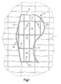
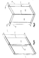
- FIG. 1 illustrates an island 10 positioned below the remainder of a suspension ceiling 11.
- the suspension ceiling is illustrated in dotted lines to emphasize the fact that the island is displaced below the surface of the ceiling.
- the particular island 10 like the ceiling 11, is provided with main grid tees 12 and cross tees 13 which are connected together in the usual manner to form panel receiving openings 14.
- the entire island is enclosed within channel shaped trim strips which provide a finished edge for the island.
- a portion of the island is enclosed by straight trim strips 16, 17, 18 and 19.
- the remainder of the island is enclosed within curved trim strips 21 and 22.
- the trim strip 21 is concavely curved and the trim strip 22 is convexly curved.
- trim strip mounting clips are mounted on the associated main tees 12 and cross tees 13 by trim strip mounting clips in accordance with the present invention.
- FIG. 1 such mounting clips are not visible because they are hidden by the panels and the trim. Further, the mounting clips do not require any exposed fasteners so the trim strips form a finished border around the entire island.
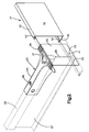
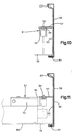
- FIGS. 2 through 4 illustrate a first embodiment of a trim strip mounting clip 23 in accordance with this invention.
- the mounting clip 23 provides a channel-shaped or inverted U-shaped support portion 24 which fits over the bulb 26 of an associated grid tee 27.
- grid tee like all of the grid tees illustrated in the various figures, provides a hollow, generally rectangular bulb 26 at the upper edge of a web 28 and oppositely extending panel supporting flanges 29 along the lower edge of the web 28.
- a transition portion 31 joins the support portion 24 to a planar face portion 32. Extending from the upper surface of the transition portion 31 are three pairs of locking tabs 33 which are inclined upwardly and rearwardly to locking edges 34.
- the support portion 24 is secured to the bulb 26 by a screw or rivet fastener 36 which ensures that the mounting clip 23 cannot move relative to the associated grid tee 27.
- the support portion is punched to provide an opening on the top and the side so that a fastener 36 can be installed in either position.
- fasteners 36 are installed on the side of the bulb when ceiling clearance prevents them from being installed on the top.
- a channel-shaped trim strip 37 is snapped into position on the mounting clip 23 and is therefore secured to and supported by the associated grid tee members.
- Such trim strip 37 provides a planar portion 38 which fits against the face portion 32 of the mounting clip.
- a lower flange 39 fits beneath the bottom edge 41 of the face portion and an upper flange 42 fits back along the upper surface of the transition portion 31 of the mounting clip.
- the upper flange 42 is provided with a hem 43 which locks against one of the pair of locking tabs to hold the upper flange tightly against the upper end of the face portion.
- the lower flange is usually provided with a hem 44, however, such hem need not engage the back side of the lower edge 41 of the face portion 32 since the engagement between the upper hem and the locking edge 34 is spaced back from the face portion and produces a force tending to maintain the lower end of the trim strip tight against the face portion.
- FIGS. 3, 4, and some of the other FIGS. clearances are shown between the mounting clip and the various portions of the trim strip for purposes of illustration.
- the trim strips are dimensioned to tightly engage the face portion 32 of the mounting clip, in fact, an interference fit is desired so that once the trim strip is snapped into its mounted position, it is tightly held by the mounting clip.
- the lower flange 39 extends under the adjacent portion of the panel supporting flanges 29. Because a hem 44 is provided on the lower flange 39, all raw edges are concealed.
- FIG. 4 illustrates the manner in which a trim strip 37a having a height exceeding the height of the grid tee 27 may be mounted on a mounting clip 23.
- the trim strip provides a lower portion 46 which snaps onto the face portion of the mounting clip 23 and an upper portion 47 which is rearwardly spaced and extends above the grid tee.
- a bead 48 is provided at the lower end of the upper portion to lock with the locking tabs.
- the mounting of the trim strip is accomplished by merely snapping the trim strip onto the associated mounting clip 23.
- the mounting clip 23 can only be used at locations where the trim strip must extend perpendicular to the associated grid tee and the grid tee ends at an off-module position.
- a mounting clip 23 could typically be used to connect the trim portion 16 illustrated in FIG. 1 to the ends of the main runners 12. Because the connector 23 is formed from a single piece of sheet metal and is very low in cost, its use is preferred in instances in which the trim strip extends perpendicular to the grid tee and is located at an off-module position.
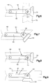
- FIGS. 5 through 14 illustrate variations in structure and use of a second embodiment mounting clip.
- Such mounting clip may be used to connect straight or curved trim strips of various heights. Further, the mounting clip can be used with trim strips which extend parallel to the supporting grid tee or at angles relative to the supporting grid tee.
- all of the variations of the mounting clip 51 provide a support portion 52 which is again channel-shaped or shaped or as an inverted "U" so as to fit down over the bulb of an associated grid tee in a manner similar to the support portion of the first embodiment.
- a pair of openings 50 are provided in the support portion 52 through which fasteners can be installed.
- the face portion 53 is connected to the support portion by a rivet 54 which permits pivotal movement of the face portion relative to the support portion through a full 180°. Therefore, the face portion 53 can extend perpendicular to the supporting grid tee as illustrated in FIGS. 6 and 8, at an angle relative to the supporting grid tee as illustrated in FIG. 7, or parallel to the supporting grid tee as illustrated in FIG. 9.
- the face portion 53 is cut out at 56 to provide a laterally extending tongue 57.
- the tongue 57 extends rearwardly to a position in which it overlays the adjacent end of the support portion and is connected thereto by the rivet 54.
- the upper end of the face portion 53 is formed with a rearwardly extending flange 58 which snaps into and locks with the associated trim strip 59.
- the lower end of the face portion 53 is provided with a rearwardly extending flange 61 which snaps into and locks with the lower end of the trim strip 59.
- the upper flange 58 is provided with a recessed, central portion 62 and a pair of upwardly extending lock portions 63.
- the support portion is formed with an end extension 64 which extends beyond the channel-shaped part thereof so that the mounting clip 51 can be installed at an intersection as illustrated in FIGS. 6 and 11.
- the support portion 52 is positioned on a grid member 66 so that the extension 64 extends beyond the end thereof and positions the pivot fastener 54 above the bulb of the grid tee 70.
- the tongue 57 is sized so that it positions the face portion 53 beyond the adjacent edge of the flange of the grid 70. Therefore, the trim strip 59 is properly positioned to extend parallel to the grid tee 70 even though it is supported by the grid tee 66 and extends perpendicular to the grid tee 66.
- the support portion 52 of the mounting clip 51 extends parallel to the adjacent grid member 70 since it is mounted at a location spaced from an intersection.
- the face portion 53 is pivoted to a position perpendicular to the support portion 52 and the face portion is again properly positioned for supporting a trim strip 59 parallel to the grid tee 70.
- the length of the tongue 57 is selected so that when the pivot 54 is directly over the bulb of an adjacent grid tee and the face portion 53 is positioned parallel to such grid tee, the face portion is properly positioned to receive the trim strip.
- the planar surface is spaced from the pivot axis by a distance slightly greater than the width of one of the panel supporting flanges of the grid tee.
- the mounting clip because of the pivoted connection between the face portion and the support portion, can be utilized to support trim strips extending parallel to the supporting grid tee and at all angles between the perpendicular and parallel position.
- the mounting clip 51 can be used to connect and support any of the trim strips illustrated in FIG. 1.
- the mounting portion When mounting the trim strip 16 the mounting portion is positioned with respect to the end of the adjacent grid tees so that the trim strip 16 extends perpendicular to and encloses the end of the associated grid tee in the manner illustrated in FIG. 8.
- the face portion When supporting the angled trim strip 17 and 18, the face portion is pivoted with respect to the support portion to properly align with such trim strips.
- the mounting clip When supporting the trim strip 19, the mounting clip can be mounted at intersections as illustrated in FIG. 11 or at locations spaced from the intersections as illustrated in FIG. 10.
- the face portion When supporting the curved trim strips 21 and 22, the face portion is appropriately pivoted relative to the supporting grid member to accommodate the particular angle at the point of support.
- the mounting clip 51 is a universal mounting clip which can be adjusted to support a trim strip in substantially any orientation with respect to the supporting grid tee member.
- FIG. 12 illustrates a variation of the second embodiment.
- a second tab 71 is bent back from the face portion 72.
- This tab 71 is sized and positioned so as to engage with the side of the web 73 of an associated grid tee 74 when the face portion is pivoted to a position parallel to the length of the grid tee 74.
- This tab provides additional stability.
- the upper flange 76 is modified to provide laterally extending locking edges 77 on either side of the recess 78.
- This structure provides a greater area of contact with the trim strip 79 than the earlier described flange locking system.
- the recess permits the insertion of a screwdriver or the like when removal of an installed trim strip is required.
- the tab 71 is lance cut from the face 72 and initially extends parallel to the face portion but is on the back side thereof. When the tab use is not required, it remains in its initial position. However, when the tab use is required, it is merely bent back perpendicular to the face portion as illustrated in FIG. 12.
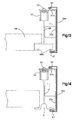
- FIGS. 13 and 14 illustrate another modified version of the second embodiment mounting clip.
- the trim strip is sized to have a height substantially equal to the height of the associate grid tee.
- the face portion 53a is bent to extend laterally providing a lateral flange 57a corresponding to the tongue 57 of the version of FIG. 5.
- Such flange is connected by pivot fastener 54 to the support portion 52.
- a locking tongue 65 is bent out from the flange 57a to lock with the upper flange of a trim strip 59a.
- the various proportions of the mounting clips are selected so that the lower flange 67 of the trim strip 59 or 59a will extend a short distance under the lower surface of the flange of a typical grid tee and also so that it will be properly positioned with respect to other forms of grid tees.
- the grid tee 68 is provided with a box-like lower flange which is open on the bottom side.
- the grid tee 68 is of the type illustrated in the United States Letters Patent No. 4,535,580 which patent is incorporated herein by reference. Such grid tees provide gaps in the lower inwardly extending lips 68a, as described in such patent, so that a "miter" type joint is provided at intersections. Since such gaps would be exposed on the outer side where no intersecting grid tee exists, the lower flange 67 of the trim strip is proportioned and positioned to extend into exact alignment with the inner edge of the outer lip 68a as illustrated in FIG. 13. Therefore, the gaps are concealed from view. The tab 71 functions to insure this precise positioning of the flange 68a.
- the same mounting clip and trim strip 59a can also be used with grid tees 68' as illustrated in FIG. 14.
- grid tees provide a hat-shaped flange structure having an upwardly extending central channel A.
- the lower flange 67 of the trim strip 59a again, extends inwardly along the adjacent flange surface but terminates back from the channel A.
- the face portion can be made of substantially any height to connect with and support trim strips of various heights. Further, if desired, the face portion can be made wider so as to function as a splice plate at abutting ends of adjacent trim strips.
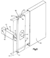
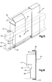
- FIGS. 15 and 16 illustrate a third embodiment of this invention.
- the mounting clip 81 is formed of a single piece of sheet metal.
- a pair of similar legs 82 are bent back from opposite sides of the face portion 83 and are shaped to mate with the web 84 and bulb 86 of the associated grid tee 87.
- Each leg 82 provides a first edge 88 which engages the side of the web 84. Above the edge 88 the legs are cut to fit around the bulb 86.
- Tabs 91 are bent up as illustrated in FIG. 15 to allow the mounting clip to be installed on the associated runner 87 and after the clip is positioned, the tabs 91 are bent down to engage the remote side of the bulb, as illustrated in FIG. 16.
- locking flanges 92 and 93 are provided at the upper and lower ends of the face portion to lock with a channel-shaped trim strip 94.
- This embodiment can only be used to connect with trim strips extending parallel to the associated grid tee but has the advantage of simplicity since the mounting clip is formed of a simple sheet metal piece bent to produce the required flanges and legs.
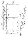
- Figures 17-21 illustrate a novel and improved splice plate for trim strips of the type discussed above.
- This splice plate may be used to interconnect abutting ends of trim strips both in a condition in which the abutting ends are in alignment, and a condition in which the abutting ends form an inside corner.
- splice plates are not required where the trim strip provides an outside corner, since the upper and lower flanges of the trim strip can be cut to form a miter-type joint. When the trim strip is bent to form the outside corner, the miter-type cut closes to provide a finished appearance.
- the abutting ends of typical straight trim strips must, on some occasions, be provided along straight sections and at inside corners.
- the splice plate of Figures 17-21 can be used to interconnect abutting ends of trim strips in either an aligned condition, as illustrated in Figure 20, or at an inside corner, as illustrated in Figure 21.
- the splice plate 111 is channel-shaped, as best illustrated in Figure 19, and provides a central planar face portion 112 and opposed laterally extending flanges 113 and 114 extending from the opposite edges 116 and 117 of the face portion.
- the dimensions of the splice plate face portion and flanges is arranged so that the splice plate can be snapped into a channel-shaped trim strip 118, as illustrated in Figure 19. In such position, the edges 121 and 122 snap in behind the adjacent hems 123 and 124 of the trim strip 118 to provide an interlocking connection with the trim strip 118.
- the face portion 112 is also formed with a laterally extending lance cut 126 which extends perpendicular to the length of the splice plate to ends 127 and 128 inwardly spaced from the associated edges 116 and 117. Therefore, the face portion provides a continuous uninterrupted section 125 extending past the lance cut 126 at both ends of the lance cut. This lance cut creates a bend line 130 along which the splice plate is bent when it is used to interconnect the abutting ends of trim strips forming an inside corner.
- each flange 113 and 114 are formed with openings 131 and 132, respectively, which are in alignment with each other as well as in alignment with the lance cut 126 and bend line 130. These openings are spaced from the associated edges 121 and 122 of the flanges as best illustrated in Figure 18. Therefore, each flange 113 and 114 provides a continuous uninterrupted portion 133 extending past the bend line and cooperates with the adjacent uninterrupted sections 125 of the face portion 112 to normally maintain the splice plate in a straight condition.
- the splice plate When the splice plate is used to interconnect the abutting ends of two aligned trim strips 118 and 118a, as illustrated in Figure 20, such abutting ends are held in aligned abutting condition since the splice plate forms a bridge between, and locks with the adjacent ends of, the two trim strips. As best illustrated in Figure 20, it is not necessary to snap the splice plate into the abutting trim strips in a completely central position in which the lance cut bend line extends along the abutting joint. However, even if the splice plate is installed so that the lance cut 126 is in alignment with the abutting joint, the splice plate provides sufficient strength to form a proper interconnection bridging the joint between the two trim strips.
- the splice plate When the splice plate is used to form an inside corner, it is merely necessary to cut through the uninterrupted portion 133 from the adjacent edge 121 and 122 to the associated opening 131 and 132. Once such a cut has been made, the splice plate can be easily bent with a sharp corner bend along the bend line 130 formed by the lance cut 126 to an angle matching the angle required for the inside corner. At such corner, the portions of the splice plate between the fold line 130 and the two ends of the splice are respectively snapped into the associated trim strips 118b and 118c, as illustrated in Figure 21. The splice plate then provides a bridging interconnection which maintains the abutting ends in proper position with respect to each other.
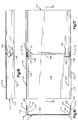
- FIGS 22-25 illustrate a variation of the splice plate described immediately above.
- This splice plate 141 is again channel-shaped, providing a central planar face portion 142, again provided with a centrally located laterally extending lance cut 143.
- flanges 144 and 146 extend from the opposite edges of the face portion 142 to provide a generally channel-shaped structure.
- the flanges 144 and 146 are again formed with openings 145 in alignment with the lance cut and spaced from the adjacent edges of the flanges to provide a central portion of the flanges with sufficient stiffening extending past the bend line 143a of the lance cut 143.
- the splice plate can also be used to interconnect abutting ends of curved trim strips to allow the installation of the splice plate 141 within curved trim strips.
- the flanges 144 and 146 are formed with lateral notches 147 at regular intervals along their length to provide spaced flange segments 147a. This allows the face portion to be bent at intervals along its length spaced from the lance cut to approximate the curvature of an associated curved trim strip. Adjacent to each lateral notch 147, an adjacent corner of each segment 147a is bent outwardly at 148 to form a locking point for engagement with the hem of a curved trim strip.
- the notches 147 have a width which spaces adjacent segments 147a. Therefore, the two ends of the splice plate can be bent inwardly or outwardly to conform with either concave or convex trim strips which are interconnected by the splice plate.
- the splice plate can be used, as illustrated in Figures 22-24, to provide a bridging connection between abutting curved trim strips.
- the portion of the flange beyond the opening 145 is again cut to allow the splice plate to be bent along the bend line formed by the lance cut 143 to form a sharp corner. Therefore, the splice plate can be used to interconnect curved or straight trim strips which are in substantial alignment where they abut, or can also be used to join curved trim strips at sharp inside corners.
- edges adjacent to the notches on either side of the openings 145 are both angled up to form locking corners on either side of the openings 145.
- the remaining flange segments between the notches 147 are bent up only at one corner so that each flange segment only locks with the adjacent flange of a curved trim strip at one point. This provides a good interconnection, even though the splice plate is not smoothly curved to conform to the curvature of the trim strip, but is only bent to approximate the curvature of the trim strip.
- the central segment with two corner tabs 148a and 148b, however, the abutting ends are locked into alignment adjacent to the abutting ends, and a good alignment is achieved.
- FIG. 24 illustrates the splice plate 141 bent to connect curved trim strips in which one end of the splice plate is bent to a concave shape to approximate the curvature of a curved trim strip, and the other end is bent to a convex shape to approximate the curvature of the other trim strip.
- the mounting clip is first mounted on the associated grid tee and the trim strip is thereafter installed by merely snapping it into the mounted position on the mounting clip. Because there are no fasteners required to connect the trim strip to the mounting clips, there are no exposed fasteners which could detract from the finished appearance of the installation. Further, because the mounting clips can be easily installed to support trim strips extending in substantially any direction relative to the associated grid tee proper, trim can be provided for edges of substantially any shape.
Landscapes
- Engineering & Computer Science (AREA)
- Architecture (AREA)
- Electromagnetism (AREA)
- Civil Engineering (AREA)
- Structural Engineering (AREA)
- Physics & Mathematics (AREA)
- Vehicle Interior And Exterior Ornaments, Soundproofing, And Insulation (AREA)
- Connection Of Plates (AREA)
- Registering, Tensioning, Guiding Webs, And Rollers Therefor (AREA)
- Pharmaceuticals Containing Other Organic And Inorganic Compounds (AREA)
- Solid-Sorbent Or Filter-Aiding Compositions (AREA)
- Details Or Accessories Of Spraying Plant Or Apparatus (AREA)
- Finishing Walls (AREA)
- Specific Sealing Or Ventilating Devices For Doors And Windows (AREA)
- Supports For Pipes And Cables (AREA)
- Buildings Adapted To Withstand Abnormal External Influences (AREA)
- Bridges Or Land Bridges (AREA)
- Insertion Pins And Rivets (AREA)
Applications Claiming Priority (4)
| Application Number | Priority Date | Filing Date | Title |
|---|---|---|---|
| US07/708,975 US5195289A (en) | 1991-05-31 | 1991-05-31 | Trim system for suspension ceilings |
| US708975 | 1991-05-31 | ||
| US819272 | 1992-01-10 | ||
| US07/819,272 US5201787A (en) | 1991-05-31 | 1992-01-10 | Trim system for suspension ceilings |
Publications (3)
| Publication Number | Publication Date |
|---|---|
| EP0516330A2 EP0516330A2 (en) | 1992-12-02 |
| EP0516330A3 EP0516330A3 (enExample) | 1994-04-20 |
| EP0516330B1 true EP0516330B1 (en) | 1998-08-05 |
Family
ID=27108180
Family Applications (1)
| Application Number | Title | Priority Date | Filing Date |
|---|---|---|---|
| EP92304550A Expired - Lifetime EP0516330B1 (en) | 1991-05-31 | 1992-05-20 | Trim system for suspension ceilings |
Country Status (11)
| Country | Link |
|---|---|
| US (1) | US5201787A (enExample) |
| EP (1) | EP0516330B1 (enExample) |
| JP (1) | JP3098323B2 (enExample) |
| KR (1) | KR100210573B1 (enExample) |
| AT (1) | ATE169362T1 (enExample) |
| AU (2) | AU643410B2 (enExample) |
| CA (1) | CA2069837C (enExample) |
| DE (1) | DE69226476T2 (enExample) |
| MX (1) | MX9202521A (enExample) |
| NZ (1) | NZ242960A (enExample) |
| SG (1) | SG43919A1 (enExample) |
Cited By (2)
| Publication number | Priority date | Publication date | Assignee | Title |
|---|---|---|---|---|
| CN102741486A (zh) * | 2009-12-22 | 2012-10-17 | Usg内部有限责任公司 | 抗震夹件 |
| US10106982B2 (en) | 2017-03-13 | 2018-10-23 | Rockwool International A/S | High strength grid member for suspended ceilings |
Families Citing this family (51)
| Publication number | Priority date | Publication date | Assignee | Title |
|---|---|---|---|---|
| US5201787A (en) * | 1991-05-31 | 1993-04-13 | Usg Interiors, Inc. | Trim system for suspension ceilings |
| US5247769A (en) * | 1992-11-19 | 1993-09-28 | Becker Kenneth G | Flexible edge molding for curved surfaces |
| EP0795657B1 (en) * | 1996-03-14 | 2001-10-24 | Hunter Douglas Industries B.V. | A ceiling mounting system |
| US6047512A (en) * | 1998-10-21 | 2000-04-11 | Usg Interiors, Inc. | Drywall suspension grid system |
| US6689451B1 (en) | 1999-11-19 | 2004-02-10 | James Hardie Research Pty Limited | Pre-finished and durable building material |
| DE10011285C2 (de) * | 2000-03-08 | 2002-02-28 | Stefan Thermann | Anschlußprofil für Deckenverkleidungen |
| DE10017638C2 (de) * | 2000-04-08 | 2002-02-07 | Profil Vertrieb Gmbh | Befestigungselement zum Anbringen C-förmiger Tragteile an Walzstahlprofilen |
| US6374564B1 (en) * | 2000-05-31 | 2002-04-23 | Usg Interiors, Inc. | Suspended curved ceiling system |
| US6298623B1 (en) | 2000-06-09 | 2001-10-09 | Usg Interiors, Inc. | Adjustable trim strip system |
| EP1377716A1 (en) | 2001-04-03 | 2004-01-07 | James Hardie Research Pty Limited | Two-piece siding plank, methods of making and installing |
| DE10217574B3 (de) * | 2002-04-19 | 2004-02-19 | Welser Profile Ag | Bausatz mit Eckverbinder |
| US8281535B2 (en) | 2002-07-16 | 2012-10-09 | James Hardie Technology Limited | Packaging prefinished fiber cement articles |
| AU2003256630B2 (en) | 2002-07-16 | 2009-08-13 | James Hardie Technology Limited | Packaging prefinished fiber cement products |
| US20050217194A1 (en) * | 2004-03-30 | 2005-10-06 | Eric Krantz-Lilienthal | Trim system for a suspended ceiling |
| AU300240S (en) | 2004-06-17 | 2004-11-18 | Hardie James Technology Ltd | Trim system component |
| AU300232S (en) | 2004-06-17 | 2004-11-18 | Hardie James Technology Ltd | Trim system component |
| AU300234S (en) | 2004-06-17 | 2004-11-18 | Hardie James Technology Ltd | Trim system component |
| AU300237S (en) | 2004-06-17 | 2004-11-18 | Hardie James Technology Ltd | Trim system component |
| AU300236S (en) | 2004-06-17 | 2004-11-18 | Hardie James Technology Ltd | Trim system component |
| AU300235S (en) | 2004-06-17 | 2004-11-18 | Hardie James Technology Ltd | Trim system component |
| AU302237S (en) | 2004-06-17 | 2005-06-29 | James Hardie Int Finance B V | Sheet cutting knife |
| AU300233S (en) | 2004-06-17 | 2004-11-18 | Hardie James Technology Ltd | Trim system component |
| AU300238S (en) | 2004-06-17 | 2004-11-18 | Hardie James Technology Ltd | Trim system component |
| AU300239S (en) | 2004-06-17 | 2004-11-18 | Hardie James Technology Ltd | Trim system component |
| AU300671S (en) | 2004-06-29 | 2005-02-11 | Hardie James Technology Ltd | Trim element |
| US7998571B2 (en) | 2004-07-09 | 2011-08-16 | James Hardie Technology Limited | Composite cement article incorporating a powder coating and methods of making same |
| US7810294B2 (en) * | 2004-09-29 | 2010-10-12 | Ig Creative Solutions, Inc. | Housing construction system |
| WO2006039664A2 (en) * | 2004-10-01 | 2006-04-13 | Carrier Corporation | Trim joint for sealing gaps between panes of flat glass |
| US7752821B2 (en) * | 2004-10-27 | 2010-07-13 | Chicago Metallic Corporation | Suspended ceiling system |
| US7690168B2 (en) | 2005-07-29 | 2010-04-06 | Usg Interiors, Inc. | Wall mold attachment clip |
| US20070256390A1 (en) * | 2005-09-29 | 2007-11-08 | Carrier Corporation | Trim joint for sealing gaps between panes of flat glass |
| US7788875B2 (en) * | 2005-11-21 | 2010-09-07 | Usg Interiors, Inc. | Trim system clip for island ceiling |
| US7578107B2 (en) * | 2005-12-02 | 2009-08-25 | Worthington Armstrong Venture | Suspended ceiling segment |
| ES2310394T3 (es) * | 2006-01-18 | 2009-01-01 | Chicago Metallic Continental | Sistema de islas para techos. |
| AU2007236561B2 (en) | 2006-04-12 | 2012-12-20 | James Hardie Technology Limited | A surface sealed reinforced building element |
| US7392629B1 (en) * | 2006-12-28 | 2008-07-01 | Usg Interiors, Inc. | Suspended ceiling system |
| US8215075B2 (en) * | 2008-03-18 | 2012-07-10 | Awi Licensing Company | Up-tight surface covering and attachment system |
| EP2182128A1 (en) | 2008-10-30 | 2010-05-05 | Chicago Metallic Continental | A suspendable ceiling island system |
| USD612224S1 (en) | 2009-02-11 | 2010-03-23 | Usg Interiors, Inc. | Perimeter trim mounting bracket |
| US7930864B2 (en) * | 2009-02-11 | 2011-04-26 | Usg Interiors, Inc. | Mounting clip |
| US20110056011A1 (en) * | 2009-08-21 | 2011-03-10 | Drechsel Lamont | Corner assemblies for swimming pools |
| WO2012050554A1 (en) * | 2010-10-11 | 2012-04-19 | Ig Creative Solutions, Inc. | Housing construction system |
| US8813457B2 (en) | 2012-06-29 | 2014-08-26 | Usg Interiors, Llc | Grid runner to perimeter trim clip |
| US8511023B1 (en) * | 2012-11-06 | 2013-08-20 | Usg Interiors, Llc | Wall panel mounting system |
| US9255403B1 (en) * | 2014-08-19 | 2016-02-09 | Usg Interiors, Llc | Free span ceiling grid system |
| US9799177B2 (en) | 2014-09-23 | 2017-10-24 | Intel Corporation | Apparatus and methods for haptic covert communication |
| US9187898B1 (en) | 2014-09-24 | 2015-11-17 | Usg Interiors, Llc | Perimeter trim clip for suspended ceilings |
| USD839078S1 (en) | 2018-01-04 | 2019-01-29 | Clarkwestern Dietrich Building Systems Llc | Slide clip |
| USD959251S1 (en) | 2020-07-22 | 2022-08-02 | Clarkwestern Dietrich Building Systems Llc | Slide clip |
| USD959250S1 (en) | 2020-07-22 | 2022-08-02 | Clarkwestern Dietrich Building Systems Llc | Slide clip |
| US11692340B2 (en) | 2020-07-22 | 2023-07-04 | Clarkwestern Dietrich Building Systems Llc | Slide clip |
Family Cites Families (13)
| Publication number | Priority date | Publication date | Assignee | Title |
|---|---|---|---|---|
| US2915150A (en) * | 1955-08-19 | 1959-12-01 | Ralph W Weidler | Basement assembly and prefabricated structural units therefor |
| US3562973A (en) * | 1969-02-14 | 1971-02-16 | Du Pont | Collapsible prefabricated structure |
| US3546842A (en) * | 1969-05-27 | 1970-12-15 | Koller Craft Plastic Products | Panel assembly |
| US4055930A (en) * | 1976-05-27 | 1977-11-01 | Ceiling Resurfacing Systems, Inc. | Grid ceiling trim |
| US4367616A (en) * | 1980-04-25 | 1983-01-11 | Pearson Ronald D | Wooden beam suspended ceiling assembly |
| US4535580A (en) * | 1981-07-09 | 1985-08-20 | Donn Incorporated | Screw slot runner system |
| DE3338037A1 (de) * | 1983-10-20 | 1985-05-02 | Richter-System GmbH & Co KG, 6103 Griesheim | Clip zur befestigung von bekleidungsplatten an walzstahlprofilen |
| US4742662A (en) * | 1986-05-05 | 1988-05-10 | Smith Owen J | Ceiling trim support clips |
| US4744188A (en) * | 1987-05-15 | 1988-05-17 | Donn Incorporated | Suspended island ceiling system |
| US4872296A (en) * | 1987-07-30 | 1989-10-10 | Duro-Last Roofing, Inc. | Corner pieces for single-ply polymer-coated fabric core roof membranes and the product thereby formed |
| US5031377A (en) * | 1989-02-13 | 1991-07-16 | Mccalla/Lackey Products Corporation | Artificial beam |
| US5088261A (en) * | 1990-12-20 | 1992-02-18 | Usg Interiors, Inc. | Curved grid tees for suspension ceilings |
| US5201787A (en) * | 1991-05-31 | 1993-04-13 | Usg Interiors, Inc. | Trim system for suspension ceilings |
-
1992
- 1992-01-10 US US07/819,272 patent/US5201787A/en not_active Expired - Lifetime
- 1992-05-20 SG SG1996005388A patent/SG43919A1/en unknown
- 1992-05-20 EP EP92304550A patent/EP0516330B1/en not_active Expired - Lifetime
- 1992-05-20 DE DE69226476T patent/DE69226476T2/de not_active Expired - Lifetime
- 1992-05-20 AT AT92304550T patent/ATE169362T1/de not_active IP Right Cessation
- 1992-05-28 MX MX9202521A patent/MX9202521A/es unknown
- 1992-05-28 CA CA002069837A patent/CA2069837C/en not_active Expired - Lifetime
- 1992-05-28 AU AU17186/92A patent/AU643410B2/en not_active Ceased
- 1992-05-29 NZ NZ242960A patent/NZ242960A/en not_active IP Right Cessation
- 1992-05-30 KR KR1019920009398A patent/KR100210573B1/ko not_active Expired - Lifetime
- 1992-06-01 JP JP04140303A patent/JP3098323B2/ja not_active Expired - Lifetime
-
1993
- 1993-08-10 AU AU44542/93A patent/AU659388B2/en not_active Expired
Cited By (3)
| Publication number | Priority date | Publication date | Assignee | Title |
|---|---|---|---|---|
| CN102741486A (zh) * | 2009-12-22 | 2012-10-17 | Usg内部有限责任公司 | 抗震夹件 |
| CN102741486B (zh) * | 2009-12-22 | 2014-06-04 | Usg内部有限责任公司 | 抗震夹件 |
| US10106982B2 (en) | 2017-03-13 | 2018-10-23 | Rockwool International A/S | High strength grid member for suspended ceilings |
Also Published As
| Publication number | Publication date |
|---|---|
| AU1718692A (en) | 1992-12-03 |
| ATE169362T1 (de) | 1998-08-15 |
| NZ242960A (en) | 1997-12-19 |
| AU659388B2 (en) | 1995-05-11 |
| MX9202521A (es) | 1992-11-01 |
| CA2069837C (en) | 2004-01-20 |
| EP0516330A3 (enExample) | 1994-04-20 |
| US5201787A (en) | 1993-04-13 |
| AU643410B2 (en) | 1993-11-11 |
| DE69226476T2 (de) | 1999-03-04 |
| CA2069837A1 (en) | 1992-12-01 |
| KR920021814A (ko) | 1992-12-18 |
| KR100210573B1 (ko) | 1999-07-15 |
| JP3098323B2 (ja) | 2000-10-16 |
| EP0516330A2 (en) | 1992-12-02 |
| JPH05156743A (ja) | 1993-06-22 |
| AU4454293A (en) | 1993-11-11 |
| DE69226476D1 (de) | 1998-09-10 |
| SG43919A1 (en) | 1997-11-14 |
Similar Documents
| Publication | Publication Date | Title |
|---|---|---|
| EP0516330B1 (en) | Trim system for suspension ceilings | |
| US5195289A (en) | Trim system for suspension ceilings | |
| US7930864B2 (en) | Mounting clip | |
| US4397127A (en) | Extendable stud for partition walls or the like | |
| US7658047B2 (en) | Suspended ceiling system | |
| US4408427A (en) | Framing system for demountable walls or the like | |
| US20080229680A1 (en) | Wall angle with pre-punched locating tabs | |
| US4679375A (en) | Suspension ceiling grid system with narrow-faced grid | |
| JPH0515857B2 (enExample) | ||
| US4484428A (en) | Suspended ceiling grid system | |
| US6763641B1 (en) | Gridless free form plank ceiling | |
| CA2106781C (en) | Partition frame structure | |
| CA2383789A1 (en) | Elongated spring clip members for storage buildings | |
| JP2710087B2 (ja) | 横葺き外装面の施工方法 | |
| JP3350891B2 (ja) | 隅棟用廻し葺き材 | |
| JP3223937B2 (ja) | 隅棟用廻し葺き材 | |
| US20060179726A1 (en) | Roof structures | |
| JP2904504B2 (ja) | パネルの設置構造 | |
| JPH0693692A (ja) | 雨樋カバー | |
| JPH0654071B2 (ja) | 組合せ出窓装置 | |
| JPH06299660A (ja) | 隅棟用廻し葺き材 | |
| JPH06307030A (ja) | 屋根の谷部用廻し葺き材 | |
| JPH116260A (ja) | 軒樋吊具および軒樋の支持構造 | |
| IE53946B1 (en) | Suspended ceiling grid system | |
| NZ203587A (en) | Exposed grid suspended ceiling:grid members centering panels |
Legal Events
| Date | Code | Title | Description |
|---|---|---|---|
| PUAI | Public reference made under article 153(3) epc to a published international application that has entered the european phase |
Free format text: ORIGINAL CODE: 0009012 |
|
| AK | Designated contracting states |
Kind code of ref document: A2 Designated state(s): AT BE CH DE ES FR GB IT LI NL SE |
|
| PUAL | Search report despatched |
Free format text: ORIGINAL CODE: 0009013 |
|
| AK | Designated contracting states |
Kind code of ref document: A3 Designated state(s): AT BE CH DE ES FR GB IT LI NL SE |
|
| 17P | Request for examination filed |
Effective date: 19941019 |
|
| 17Q | First examination report despatched |
Effective date: 19960206 |
|
| GRAG | Despatch of communication of intention to grant |
Free format text: ORIGINAL CODE: EPIDOS AGRA |
|
| GRAG | Despatch of communication of intention to grant |
Free format text: ORIGINAL CODE: EPIDOS AGRA |
|
| GRAH | Despatch of communication of intention to grant a patent |
Free format text: ORIGINAL CODE: EPIDOS IGRA |
|
| GRAH | Despatch of communication of intention to grant a patent |
Free format text: ORIGINAL CODE: EPIDOS IGRA |
|
| GRAA | (expected) grant |
Free format text: ORIGINAL CODE: 0009210 |
|
| AK | Designated contracting states |
Kind code of ref document: B1 Designated state(s): AT BE CH DE ES FR GB IT LI NL SE |
|
| PG25 | Lapsed in a contracting state [announced via postgrant information from national office to epo] |
Ref country code: IT Free format text: LAPSE BECAUSE OF FAILURE TO SUBMIT A TRANSLATION OF THE DESCRIPTION OR TO PAY THE FEE WITHIN THE PRE;WARNING: LAPSES OF ITALIAN PATENTS WITH EFFECTIVE DATE BEFORE 2007 MAY HAVE OCCURRED AT ANY TIME BEFORE 2007. THE CORRECT EFFECTIVE DATE MAY BE DIFFERENT FROM THE ONE RECORDED.SCRIBED TIME-LIMIT Effective date: 19980805 Ref country code: LI Free format text: LAPSE BECAUSE OF FAILURE TO SUBMIT A TRANSLATION OF THE DESCRIPTION OR TO PAY THE FEE WITHIN THE PRESCRIBED TIME-LIMIT Effective date: 19980805 Ref country code: CH Free format text: LAPSE BECAUSE OF FAILURE TO SUBMIT A TRANSLATION OF THE DESCRIPTION OR TO PAY THE FEE WITHIN THE PRESCRIBED TIME-LIMIT Effective date: 19980805 Ref country code: ES Free format text: THE PATENT HAS BEEN ANNULLED BY A DECISION OF A NATIONAL AUTHORITY Effective date: 19980805 Ref country code: BE Free format text: LAPSE BECAUSE OF FAILURE TO SUBMIT A TRANSLATION OF THE DESCRIPTION OR TO PAY THE FEE WITHIN THE PRESCRIBED TIME-LIMIT Effective date: 19980805 Ref country code: AT Free format text: LAPSE BECAUSE OF FAILURE TO SUBMIT A TRANSLATION OF THE DESCRIPTION OR TO PAY THE FEE WITHIN THE PRESCRIBED TIME-LIMIT Effective date: 19980805 Ref country code: NL Free format text: LAPSE BECAUSE OF FAILURE TO SUBMIT A TRANSLATION OF THE DESCRIPTION OR TO PAY THE FEE WITHIN THE PRESCRIBED TIME-LIMIT Effective date: 19980805 |
|
| REF | Corresponds to: |
Ref document number: 169362 Country of ref document: AT Date of ref document: 19980815 Kind code of ref document: T |
|
| REG | Reference to a national code |
Ref country code: CH Ref legal event code: EP |
|
| REF | Corresponds to: |
Ref document number: 69226476 Country of ref document: DE Date of ref document: 19980910 |
|
| ET | Fr: translation filed | ||
| PG25 | Lapsed in a contracting state [announced via postgrant information from national office to epo] |
Ref country code: SE Free format text: LAPSE BECAUSE OF FAILURE TO SUBMIT A TRANSLATION OF THE DESCRIPTION OR TO PAY THE FEE WITHIN THE PRESCRIBED TIME-LIMIT Effective date: 19981105 |
|
| NLV1 | Nl: lapsed or annulled due to failure to fulfill the requirements of art. 29p and 29m of the patents act | ||
| REG | Reference to a national code |
Ref country code: CH Ref legal event code: PL |
|
| PLBE | No opposition filed within time limit |
Free format text: ORIGINAL CODE: 0009261 |
|
| STAA | Information on the status of an ep patent application or granted ep patent |
Free format text: STATUS: NO OPPOSITION FILED WITHIN TIME LIMIT |
|
| 26N | No opposition filed | ||
| REG | Reference to a national code |
Ref country code: GB Ref legal event code: IF02 |
|
| PGFP | Annual fee paid to national office [announced via postgrant information from national office to epo] |
Ref country code: FR Payment date: 20110607 Year of fee payment: 20 |
|
| PGFP | Annual fee paid to national office [announced via postgrant information from national office to epo] |
Ref country code: GB Payment date: 20110525 Year of fee payment: 20 |
|
| PGFP | Annual fee paid to national office [announced via postgrant information from national office to epo] |
Ref country code: DE Payment date: 20110527 Year of fee payment: 20 |
|
| REG | Reference to a national code |
Ref country code: DE Ref legal event code: R071 Ref document number: 69226476 Country of ref document: DE |
|
| REG | Reference to a national code |
Ref country code: DE Ref legal event code: R071 Ref document number: 69226476 Country of ref document: DE |
|
| REG | Reference to a national code |
Ref country code: GB Ref legal event code: PE20 Expiry date: 20120519 |
|
| PG25 | Lapsed in a contracting state [announced via postgrant information from national office to epo] |
Ref country code: DE Free format text: LAPSE BECAUSE OF EXPIRATION OF PROTECTION Effective date: 20120522 |
|
| PG25 | Lapsed in a contracting state [announced via postgrant information from national office to epo] |
Ref country code: GB Free format text: LAPSE BECAUSE OF EXPIRATION OF PROTECTION Effective date: 20120519 |