EP0514176A2 - Schrittmotor - Google Patents
Schrittmotor Download PDFInfo
- Publication number
- EP0514176A2 EP0514176A2 EP92304367A EP92304367A EP0514176A2 EP 0514176 A2 EP0514176 A2 EP 0514176A2 EP 92304367 A EP92304367 A EP 92304367A EP 92304367 A EP92304367 A EP 92304367A EP 0514176 A2 EP0514176 A2 EP 0514176A2
- Authority
- EP
- European Patent Office
- Prior art keywords
- cylindrical
- magnetic
- poles
- path forming
- forming means
- Prior art date
- Legal status (The legal status is an assumption and is not a legal conclusion. Google has not performed a legal analysis and makes no representation as to the accuracy of the status listed.)
- Granted
Links
- 230000004907 flux Effects 0.000 claims abstract description 59
- 239000000696 magnetic material Substances 0.000 claims abstract description 34
- 230000002093 peripheral effect Effects 0.000 claims abstract description 17
- ZZBAGJPKGRJIJH-UHFFFAOYSA-N 7h-purine-2-carbaldehyde Chemical compound O=CC1=NC=C2NC=NC2=N1 ZZBAGJPKGRJIJH-UHFFFAOYSA-N 0.000 claims 2
- XEEYBQQBJWHFJM-UHFFFAOYSA-N Iron Chemical group [Fe] XEEYBQQBJWHFJM-UHFFFAOYSA-N 0.000 description 48
- 239000011295 pitch Substances 0.000 description 45
- 230000001939 inductive effect Effects 0.000 description 20
- 230000005284 excitation Effects 0.000 description 8
- 238000000034 method Methods 0.000 description 4
- 229920006395 saturated elastomer Polymers 0.000 description 3
- 238000004804 winding Methods 0.000 description 2
- RYGMFSIKBFXOCR-UHFFFAOYSA-N Copper Chemical compound [Cu] RYGMFSIKBFXOCR-UHFFFAOYSA-N 0.000 description 1
- PMVSDNDAUGGCCE-TYYBGVCCSA-L Ferrous fumarate Chemical group [Fe+2].[O-]C(=O)\C=C\C([O-])=O PMVSDNDAUGGCCE-TYYBGVCCSA-L 0.000 description 1
- 235000010469 Glycine max Nutrition 0.000 description 1
- 244000068988 Glycine max Species 0.000 description 1
- 229910052802 copper Inorganic materials 0.000 description 1
- 239000010949 copper Substances 0.000 description 1
- 238000004519 manufacturing process Methods 0.000 description 1
- 239000000463 material Substances 0.000 description 1
- 238000004513 sizing Methods 0.000 description 1
Images


Classifications
-
- H—ELECTRICITY
- H02—GENERATION; CONVERSION OR DISTRIBUTION OF ELECTRIC POWER
- H02K—DYNAMO-ELECTRIC MACHINES
- H02K37/00—Motors with rotor rotating step by step and without interrupter or commutator driven by the rotor, e.g. stepping motors
- H02K37/10—Motors with rotor rotating step by step and without interrupter or commutator driven by the rotor, e.g. stepping motors of permanent magnet type
- H02K37/12—Motors with rotor rotating step by step and without interrupter or commutator driven by the rotor, e.g. stepping motors of permanent magnet type with stationary armatures and rotating magnets
- H02K37/14—Motors with rotor rotating step by step and without interrupter or commutator driven by the rotor, e.g. stepping motors of permanent magnet type with stationary armatures and rotating magnets with magnets rotating within the armatures
-
- H—ELECTRICITY
- H02—GENERATION; CONVERSION OR DISTRIBUTION OF ELECTRIC POWER
- H02K—DYNAMO-ELECTRIC MACHINES
- H02K37/00—Motors with rotor rotating step by step and without interrupter or commutator driven by the rotor, e.g. stepping motors
- H02K37/10—Motors with rotor rotating step by step and without interrupter or commutator driven by the rotor, e.g. stepping motors of permanent magnet type
- H02K37/12—Motors with rotor rotating step by step and without interrupter or commutator driven by the rotor, e.g. stepping motors of permanent magnet type with stationary armatures and rotating magnets
-
- H—ELECTRICITY
- H02—GENERATION; CONVERSION OR DISTRIBUTION OF ELECTRIC POWER
- H02K—DYNAMO-ELECTRIC MACHINES
- H02K37/00—Motors with rotor rotating step by step and without interrupter or commutator driven by the rotor, e.g. stepping motors
- H02K37/10—Motors with rotor rotating step by step and without interrupter or commutator driven by the rotor, e.g. stepping motors of permanent magnet type
- H02K37/20—Motors with rotor rotating step by step and without interrupter or commutator driven by the rotor, e.g. stepping motors of permanent magnet type with rotating flux distributors, the armatures and magnets both being stationary
Definitions
- This invention relates to a rotary pulse motor, for example a motor which is suitable for an FA (Factory Automation) machine such as an industrial robot for which a relatively large torque is required.
- FA Vectory Automation
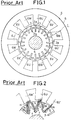
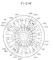
- Fig. 1 shows a first prior art rotary pulse motor which this Applicant previously developed.
- a cylindrical rotor 1 is made of magnetic material.
- Slit-like grooves 2 b , 2 b ----- are formed at an angular regular pitch in the peripheral portion of the rotor 1.
- a shaft 4 is fixed to a central hole of the rotor 1, and it is rotatably supported.
- Pairs of magnetic poles (6U, 6U), (6V′, 6V′), (6W, 6W), (6U′, 6U′), (6V, 6V) and (6W′, 6W′) are formed in symmetry with respect to the axis or shaft 4, in the inner peripheral portion of a cylindrical stator 5 made of magnetic material. Not-shown coils are wound on the magnetic poles 6U to 6W′.
- Pulse currents are, in turn, supplied to the coils.
- the rotor 1 is rotated stepwisely.
- the principle of the operation of the rotary pulse motor is described in detail, in the Japanese Patent Application No.260923/1989.
- Such a rotary pulse motor is controlled in an open-loop manner, and so can position apparatus with high accuracy. Accordingly, it is used for driving a carriage in a printer which is one example of the FA machine.
- the torque is not so large as satisfactory. It is not suitable for the FA machine such as industrial robot for which a relatively large torque is required.
- the reason is as follows :
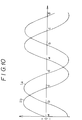
- the teeth 2 a , 2 a extend in radial directions. Accordingly, areas of magnetic paths through which magnetic fluxes H flow, are narrower towards the center of the rotor 1 or the shaft 4, as shown in Fig. 2.
- the portions 7 of the teeth 2 a , 2 a , 2 a ---- facing to the inner ends of the permanent magnets 3 are narrowest.
- the amount of the magnetic flux is limited. It cannot be larger than the saturable flux amount. Thus, a torque cannot be larger than the torque corresponding to the saturated flux amount.
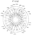
- Fig. 3 shows a second prior art rotary pulse motor which was developed by this Applicant and of a three-phase type and an inner-rotor type.
- a cylindrical rotor 11 made of magnetic material is fixed to a shaft 16 at its central hole.
- teeth 12 a , 12 a ------ and slit-like grooves 12 b , 12 b ------ are alternately formed at an angular regular pitch in the peripheral portion of the rotor 11.
- Six magnetic poles 14A, 14B, 14C, 14A′, 14B′, 14C′ are formed at an angular regular pitch in the inner peripheral portion of a cylindrical stator 14 made of magnetic material.
- the magnetic poles 14A′, 14B′ and 14C′ are excited in opposite polarity to the magnetic poles 14A, 14B and 14C, respectively.
- Coils 15A, 15B, 15C, 15A′, 15B′ and 15C′ are wound on the magnetic poles 14A, 14B,-----14C′, respectively.
- Magnetic teeth 14Aa, 14Ba, 14Ca, 14A′a, 14B′a and 14C′a are formed in the top end portions of the magnetic poles 14A, 14B, 14C, 14A′, 14B′ and 14C′, respectively.
- Pulse currents in opposite polarities are supplied to the coils 15A, 15A′ for A-phase and A′-phase, coils 15B, 15B′ for B-phase and B′-phase and coils 15C and 15C′ for C-phase and C′-phase.
- FIG. 5 shows a third prior art rotary pulse motor which was developed by this Applicant and of three-phase type and outer-rotor type.
- Magnetic teeth 22 a , 22 a ---- are formed at an angular regular pitch in an inner surface of a cylindrical rotor 21 made of magnetic material.
- Magnetic poles 25A for A-phase, 25B for B-phase, 25C for C-phase, 25A′ for A′-phase, 25B′ for B′-phase and 25C′ for C′-phase are formed at an angular regular pitch in a peripheral portion of a cylindrical stator 24 made of magnetic material.
- Coils 26A, 26B, 26C, 26A′, 26B′ and 26C′ are wound on the magnetic poles 25A, 25B, 25C, 25A′, 25B′ and 25C′, respectively.
- the magnetic poles 25A′, 25B′ and 25C′ are energized in opposite polarity to the magnetic poles 25A, 25B and 25C.
- Teeth 28, 28 ---- and slit-like grooves 29, 29 are formed alternately at an angular regular pitch in top end surfaces of the magnetic poles 25A, 25B, 25C, 25A′, 25B′ and 25C′, respectively.
- Permanent magnets 23 are inserted into the slit-like grooves 29 so that the teeth 28, 28 are polarized alternately in opposite polarity.
- a shaft 27 is fixed to the stator 24 at the central hole.
- Pulse currents are, in turn, supplied to the coils 26A, 26B, 26C, 26A′, 26B′ and 26C′.
- the secondary rotor 21 is rotated stepwisely by the well-known principle which is described in detail, in the Japanese Patent Application No.301965/1988.
- This prior art rotary pulse motor has the same disadvantage as the above-described rotary pulse motors of Fig. 1 and Fig. 3.
- the amounts of the magnetic fluxes are limited there. When the amount of the magnetic flux is larger there than a predetermined value, the magnetic fluxes are saturated. A larger torque cannot be obtained.
- the weight of the rotary pulse motor is large, and its cost is high.
- a rotary pulse motor comprising : (A)a first cylindrical magnetic-path forming means made of magnetic material ; (B)a second cylindrical magnetic-path forming means made of magnetic material and inserted concentrically into said first cylindrical magnetic-path forming means, said first cylindrical magnetic-path forming means or said second cylindrical magnetic-path forming means being rotatably supported ; (C)slit-like grooves formed at a regular angular pitch P/2 in a peripheral portion of one of said first and second cylindrical magnetic-path forming means ; (D)teeth formed between said slit-like grooves ; (E)permanent magnets inserted into said slit-like grooves and so arranged that polarities of said teeth are alternately inverted ;(F)magnetic-pole means formed at a regular angular pitch of a constant multiplier by said P/2, in the other of said first and second cylindrical magnetic-path forming means, said magnetic pole means facing to said teeth at a constant air gap
- At least some of the embodiments of the invention described below provide a rotary pulse motor which can generate a large torque, which can be easily manufactured, and/or which is lower in cost.
- a cylindrical rotor 41 (secondary) made of magnetic material is inserted concentrically into a cylindrical stator 40 (primary) made of magnetic material.
- a shaft 33 made of magnetic material is fixed to a central hole of the rotor 41, and it is rotatably supported by not-shown bearings.
- the rotor 41 can be rotated in directions shown by an arrow M.
- Teeth 42 a , 42 a ------ and slit-like grooves 42 b , 42 b ------ are formed alternately at an angular regular pitch P/2 in a peripheral portion of the rotor 41.
- Permanent magnets 43 are inserted into the slit-like grooves 42 b , 42 b ------so that the teeth 42 a , 42 a ------ are magnetized alternately in opposite polarities.
- a first row of magnetic poles 44Aa, 44Ba, 44Ca, 44Da, 44Ea, 44Fa, 44Ga and 44Ha and a second row of magnetic poles 44Ab, 44Bb, 44Cb, 44Db, 44Eb, 44Fb, 44Gb and 44Hb are formed in an inner periphery of an iron core 44 constituting the stator 40.
- Coils 45Aa, 45Ba, 45Ca, 45Da, 45Ea, 45Fa, 45Ga and 45Ha are wound on the magnetic poles 44Aa, 44Ba, 44Ca, 44Da, 44Ea, 44Fa, 44Ga and 44Ha, respectively, while coils 45Ab, 45Bb, 45Cb, 45Db, 45Eb, 45Gb and 45Hb are wound on the magnetic poles 44Ab, 44Bb, 44Cb, 44Db, 44Eb, 44Fb, 44Gb and 44Hb, respectively.
- the stator 40 consists of the iron core 44 and the coils 45Aa to 45Ha, 45Ab to 45Hb.
- the magnetic poles 44Aa to 44Ha, 44Ab to 44Hb are facing to the rotor 41 at a constant air gap G.
- the pitch of the teeth 42 a magnetized in the same polarity is equal to P.
- the magnetic poles 44Ba, 44Ca, 44Da, 44Ea, 44Fa, 44Ga and 44Ha are arranged at the phase differences P/4, 2P/4, 3P/4, 0, P/4, 2P/4 and 3P/4 with respect to the magnetic pole 44Aa.
- the phase differences between the adjacent magnetic poles 44Aa and 44Ba, 44Ba and 44Ca, ------ are 90 degrees.
- phase differences between the adjacent magnetic poles 44Ab and 44Bb, 44Bb and 44Cb, ------ are 90 degrees in the second row.
- the first row of the magnetic poles 44Aa to 44Ha is shifted by a predetermined length s from the second row of the magnetic-poles 44Ab to 44Hb in the axial direction, as shown in Fig. 8, and the phase difference between the former and the latter is equal to P/2.
- coil 45Aa and 45Ab are wound in such a direction that magnetic fluxes in opposite directions are generated in the magnetic poles 44Aa and 44Ab, respectively.
- coils 45Ba and 45Bb, 45Ca and 45Cb ------ and 45Ha and 45Hb are wound in such a direction that magnetic forces in opposite directions are generated in the magnetic poles 44Ba and 44Bb, ------ and 44Ha and 44Hb, respectively.
- the coils 45Aa to 45Ha and 45Ab to 45Hb are connected in the manner shown in Fig. 9.
- Terminals Ta and Tb are connected to the paired magnetic poles 45Aa and 45Ab, 45Ca and 45Cb, 45Ea and 45Eb and 45Ga and 45Gb.
- Terminals Tc and Td are connected to the paired magnetic poles 45Ba and 45Bb, 45Da and 45Db, 45Fa and 45Fb and 45Ha and 45Hb.
- a pulse current is supplied alternately through the terminals Ta and Tb, and Tc and Td.
- the rotary pulse motor is driven in one-phase excitation method.
- the coils are, in turn, energized by the pulse currents in the manners as described in the above (1) ⁇ (2) ⁇ (3) ⁇ (4).
- the rotor 41 is rotated in the clockwise direction, in the drawings.
- the coil are energized in the order of (4) ⁇ (3) ⁇ (2) ⁇ (1), the rotor 41 is rotated in anti-clockwise direction.
- the two rows of the magnetic-poles 44Aa to 44Ha and 44Ab to 44Hb are formed at the phase difference of 180 degrees from each other, in the stator 40.
- two rows of magnetic-poles 44Ab to 44Hb and 44Ac to 44Hc are formed at both sides of the central row of magnetic-poles 44Aa to 44Ha, and they are shifted at the phase of 180 degrees from the central row.
- Coils 45Aa to 45Ha are wound only on the central magnetic-poles 44Aa to 44Ha, and they are energized in the above described manner.
- the rotor 41 is rotated in the clockwise direction or anti-clockwise direction.
- a shaft 33 a fixed to the central hole of the rotor 41 is made of non-magnetic material, not magnetic-material.
- the flux from the N-polarity of the one permanent magnet 43 flows dirctly to the S-polarity thereof (short-circuited), when not energized.
- the permanent magnets 43 contact with the shaft 33 a made of non-magnetic material. Accordingly, the inner ends of the adjacent teeth 42 a are intercepted magnetically from each other.
- FIG. 19A and 19B show a fourth embodiment of this invention.
- a cylindrical rotor 51 made of magnetic material is inserted into a cylindrical stator 50 made of magnetic material.
- the rotor 51 is supported at its center by a shaft 46 made of magnetic-material.
- the shaft 46 is rotatably supported by not-shown bearings.
- Teeth 52 a , 52 a ------ and slit-like grooves 52 b , 52 b ------ are alternately formed in a peripheral portion of the rotor 51.
- Permanent magnets 52 are so inserted into the slit-like grooves 52 b , 52 b ------ that the teeth 52 a , 52 a , ------ are magnetized alternately in opposite polarities.
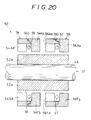
- the stator 50 include a first iron core 54 and a second iron core 56.
- Two rows of magnetic poles 54Aa to 54Ja, and magnetic poles 54Ab to 54Jb are formed at angular regular pitches in an inner peripheral portion of the first iron core 54.
- two rows of magnetic-poles 56Aa to 56Ja, and magnetic poles 56Ab to 56Jb are formed at angular regular pitches in an inner peripheral portion of the second iron core 56 as shown in Fig. 19B.
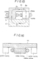
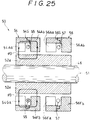
- the first iron core 54 and the second iron core 56 consist of two pieces, respectively. Annular coils 55 and 57 are inserted in annular grooves between the two pieces as shown in Fig. 20. The two pieces are fitted to each other at contact surfaces 54S, and 56S, respectively.
- the stator 50 consists of the first and second cores 54 and 56, the coils 55 and 57.
- the pitch between the teeth 52 a magnetized in the same polarity is equal to P.
- the magnetic poles 54Aa to 54Ja and 54Ab to 54Jb are formed at the constant pitch P, in the core 54.
- the one row of the magnetic poles 54Aa to 54Ja is shifted at the pitch of P/2 from the other row of the magnetic-poles 54Ab to 54Jb.
- the magnetic-poles 56Aa to 56Ja and 56Ab to 56Jb are formed at the constant pitch P in the other core 56.
- the one row of the magnetic-poles 56Aa to 56Ja is shifted at the pitch of P/2 from the other row of the magnetic poles 56Ab to 56Jb.
- the magnetic poles of the first core 54 are shifted by the pitch of P/4 from those of the second core 56.
- the pitch P corresponds to the phase difference of 360 degrees. Accordingly, the pitches P/2 and P/4 correspond to the 180 degrees and 90 degrees, respectively.
- the coils 55 and 57 are energized in the one-phase excitation method in which they are alternately energized.
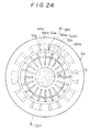
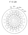
- the rotor 51 takes such a magnetically stable position that the end surfaces of the magnetic poles 56Aa to 56Ja of the second iron core 56 are facing to the S-polarized teeth 52 a of the rotor 51, and the end surfaces of the magnetic-poles 56Ab to 56Jb are facing to the N-polarized teeth 52 a of the rotor 51, as shown in Fig. 28.
- the pulse excitation is repeated in the above described order of (1) ⁇ (2) ⁇ (3) ⁇ (4).
- the rotor 51 is rotated in the clockwise direction.
- the pulse excitation is repeated in the order of (4) ⁇ (3) ⁇ (2) ⁇ (1), the rotor 51 is rotated in the anti-clockwise direction.
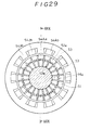
- Fig. 29 and Fig. 30 Parts in Fig. 29 and Fig. 30 which correspond to those in Fig. 19 and Fig. 20, are denoted by the same reference numerals, the description of which will be omitted.
- a shaft 46 a fixed to the central hole of the rotor 51 is made of non-magnetic material, not magnetic-material.
- the opposite polarities of the permanent magnets 53 are short-circuited.
- the permanent magnets 53 contact with the shaft 46 a made of non-magnetic material. Accordingly, the adjacent teeth 52 a are intercepted magnetically from each other.
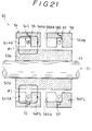
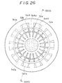
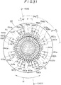
- Fig. 31 shows a sixth embodiment of this invention.
- a cylindrical rotor 61 made of magnetic material is inserted into a cylindrical stator 60 made of magnetic material.
- the rotor 61 is supported at its center by a shaft 56 made of magnetic material fixed to a central hole of the rotor 61, and it is rotatably supported by not-shown bearings.
- the rotor 61 can be rotated in the directions shown by an arrow M.
- Teeth 62 a , 62 a ------ and slit-like grooves 62 a , 62 b ⁇ ----- are formed alternately at an angular regular pitch P/2 in a peripheral portion of the rotor 61.
- Permanent magnets 63 are inserted into the slit-like grooves 62 b , 62 b ------so that the teeth 62 a , 62 a ------ are magnetized alternately in opposite polarity.
- a first row of magnetic poles 64Aa, 64Ba, 64Ca, 64Da, 64Ea, 64Fa, 64Ga and 64Ha and a second row of magnetic poles 64Ab, 64Bb, 64Cb, 64Db, 64Eb, 64Fb, 64Gb and 64Hb are formed in an inner periphery of an iron core 64 constituting the stator 60.
- Coils 65Aa, 65Ba, 65Ca, 65Da, 65Ea, 65Fa, 65Ga and 65Ha are wound on the magnetic poles 64Aa, 64Ba, 64Ca, 64Da, 64Ea, 64Fa, 64Ga and 64Ha, respectively, while coils 65Ab, 65Bb, 65Cb, 65Db, 65Eb, 65Gb and 65Hb are wound on the magnetic poles 64Ab, 64Bb, 64Cb, 64Db, 64Eb, 64Fb, 64Gb and 64Hb, respectively.
- the stator 60 consists of the iron core 64 and the coils 65Aa to 65Ha, 65Ab to 65Hb.
- the magnetic poles 64Aa to 64Ha, 64Ab to 64Hb are facing to the rotor 61 at a constant air gap G.
- the pitch of the teeth 62 a magnetized in the same polarity is equal to P.
- the magnetic poles 64Ba, 64Ca, 64Da, 64Ea, 64Fa, 64Ga and 64Ha are arranged at the phase differences P/2 with respect to the magnetic pole 64Aa.
- the phase differences between the adjacent magnetic poles 64Aa and 64Ba, 64Ba and 64Ca, ------ are 180 degrees.
- the phase differences between the adjacent magnetic poles 64Ab and 64Bb, 64Bb and 64Cb, ------ are 180 degrees in the second row.
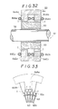
- the first row of the magnetic poles 64Aa to 64Ha is shifted by a predetermined length from the second row of the magnetic-poles 64Ab to 64Hb in the axial direction, as shown in Fig. 32, and the phase difference between the former and the latter is equal to P/2.
- the coil 65Aa and 65Ab are wound in such a direction that magnetic fluxes in opposite directions are generated in the magnetic poles 64Aa and 64Ab, respectively.
- coils 65Ba and 65Ba, 65Ca and 65Cb ------ and 65Ha and 65Hb are wound in such a direction that magnetic fluxes in opposite directions are generated in the magnetic poles 64Ba and 64Bb, ------ and 64Ha and 64Hb, respectively.
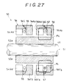
- Magnetic teeth T, T are formed in the top ends of the magnetic poles 64Aa to 64Ha and 64Ab to 64Hb.
- the width of the magnetic teeth T is substantially equal to that of the teeth 62 a
- the magnetic circuits are short-circuited by the inner-most magnetic-loops formed between the N-polarity of the permanent magnets 63 and the S-polarity thereof.
- the coils 65Aa to 65Ha and 65Ab to 65Hb are connected in the manner shown in Fig. 9. Not-shownterminals for A-phase are connected to the paired magnetic poles 65Aa and 65Ab, 65Ca and 65Cb, 65Ea and 65Eb and 65Ga and 65Gb. Not-shown terminals for B-phase are connected to the paired magnetic poles 65Ba and 65Bb, 65Da and 65Db, 65Fa and 65Fb and 65Ha and 65Hb.
- a current is supplied alternately through the terminals for A-phase and B-phase.
- the rotary pulse motor is driven in one-phase excitation method.
- the exciting mode of the above operation (1) and (2) is repeated.
- the rotor 61 is rotated.
- Fig. 35 shows a seventh embodiment of this invention.
- three rows of magnetic poles 64Aa to 64Ha, 64Ab to 64Hb and 64Ac to 64Hc are formed on the inner periphery of the iron core 64.
- Coils 65Aa to 65Ha are wound only on the central row of magnetic poles 64Aa to 64Ha.
- the two rows of magnetic poles 64Ab to 64Hb and 64Ac to 64Hc are shifted by 180 degrees from the central rows of magnetic pole 64Aa to 64Ha, respectively.
- the magnetic poles are formed at the same pitches as those of the sixth embodiment of Fig. 31, in the respective rows.
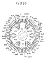
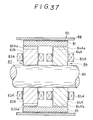
- Fig. 36 and Fig. 37 show an eighth embodiment of this invention.
- a rotary pulse motor of this embodiment is of an outer-rotor type.
- Teeth 80 a , 80 a , ------ and slit-like grooves 80 b , 80 b ------ are formed at an constant pitch of P/2 in an inner periphery of a cylindrical rotor 80 made of magnetic material.
- Permanent magnets 81, 81 ------ are so inserted into the slit-like grooves 80b, 80 b , ------ that the teeth 80 a , 80 a , ----- are alternately magnetized in opposite polarities.
- a first cylindrical stator 82 is inserted concentrically into the cylindrical rotor 80 at a constant air gap G.
- Six magnetic poles 82A, 82B, 82C, 82A′, 82B′ and 82C′ are formed at an angular regular pitch in a periphery of the first cylindrical stator 82.
- Coils 83A, 83B, 83C, 83A′, 83B′, and 83C′ are wound on the magnetic poles 82A to 82C′, respectively.
- Magnetic teeth 82Aa, 82Ba, 82Ca, 82A′a, 82B′a and 82C′a are formed on the top ends of the magnetic poles 82A to 82C′.
- a second cylindrical stator 84 is inserted into the cylindrical rotor 80 and is arranged at the back of the first cylindrical stator 82, as shown in Fig. 37. They are spaced from each other by a predetermined length in the axial direction.
- Six magnetic poles 84A, 84B, 84C, 84A′, 84B′ and 84C′ are formed at a regular angular pitch in a periphery of the second cylindrical stator 84.
- Coils 85A, 85B, 85C, 85A′, 85B′ and 85C′ are wound on the magnetic poles 84A′ to 84C′. Teeth 84Aa to 84C′a are formed on the top ends of the magnetic poles 84A to 84C′.
- a shaft 89 is fixed to the aligned central holes of the first and second cylindrical stators 82 and 84.
- the magnetic poles 82Aa to 82C′a of the first cylindrical stator 82 is shifted by a pitch of P/2 from the magnetic poles 84Aa to 84C′a of the second cylindrical stator 84.
- the operation principle of this embodiment is the same as that of the sixth embodiment.
- Fig. 38 to Fig. 44 show a ninth embodiment of this invention.
- a rotary pulse motor of this embodiment is of an outer-rotor type and two-phase type.
- the cylindrical rotor 90 is rotatably supported by a not-shown bearing mechanism. It is rotatable in the directions shown by the arrow M in Fig. 38.
- the cylindrical rotor 90 includes first and second magnetic sections 94 and 95 spaced from each other in an axial direction, as shown in Fig. 39.
- Two rows of magnetic teeth 94Aa to 94Ya and 94Ab to 94Yb are formed on an inner periphery of the first magnetic section 94.
- Magnetic teeth 94Aa to 94Ya, and 94Ab to 94Yb are formed at an angular regular pitch of P, respectively, and the phase of the formers is equal to that of the latters.
- Magnetic teeth 95Aa to 95Ya, and 95Ab to 95Yb are formed on an inner periphery of the second magnetic section 95.
- Magnetic teeth 95Aa to 95Ya, and 95Ab to 95Yb are formed at an angular regular pitch of P, respectively, and the phase of the formers is equal to that of the latters. Accordingly, the phases of all the magnetic poles 94Aa to 94Ya, 94Ab to 94Yb, 95Aa to 95Ya and 95Ab to 95Yb are equal to each other.
- the cylindrical stator 91 consists of first and second cores 92 and 93 spaced from each other in the axial direction. As shown in Fig. 39, two rows of inductive teeth 92Aa to 92Ya and 92Ab to 92Yb are formed at an angular regular pitch in a periphery of the first core 92, facing to the magnetic teeth 94Aa to 94Ya and 94Ab to 94Yb. An annular groove is formed between the two rows. An annular coil 96 is wound on the groove.
- two rows of inductive teeth 93Aa to 93Ya and 93Ab to 93Yb are formed at an angular regular pitch in a periphery of the second core 93, facing to the magnetic teeth 95Aa to 95Ya and 95Ab to 95Yb.
- An annular groove is formed between the two rows.
- An annular coil 96 is wound on the groove.
- permanent magnets 98 are inserted into slit-like grooves between the inductive teeth 92Aa to 92Ya, 92Ab to 92Yb so that the inductive teeth 92Aa to 92Ya, 92Ab to 92Yb are magnetized alternately in opposite polarities.
- the pitches of the inductive teeth 92Aa to 92Ya, and 92Ab to 92Yb are equal to P/2, respectively.
- the one inductive teeth 92Aa to 92Ya are shifted by a pitch of P/4 from the other inductive teeth 92Ab to 92Yb.
- permanent magnets 98 are inserted into slit-like grooves between the inductive teeth 93Aa to 93Ya, 93Ab to 93Yb so that the inductive teeth 93Aa to 93Ya, 93Ab to 93Yb are magnetized alternately in opposite polarities.
- the pitches of the inductive teeth 93Aa to 93Ya, and 93Aa to 93Yb are equal to P/2, respectively.
- the one inductive teeth 93Aa to 93Ya are shifted by a pitch of P/4 from the other inductive teeth 93Ab to 93Yb.
- the inductive teeth 92Aa to 92Ya and 92Ab to 92Yb of the first iron core 92 are shifted by a pitch of P/4 from the inductive teeth 93Aa to 93Ya and 93Ab to 93Yb of the second iron core 93.
- Pulse currents are supplied to the coil 96 and 97, in the order as shown in Fig. 41 to Fig. 44.
- the rotor 90 is rotated P/4 by P/4 on the basis of the Soya's principle, as described for example, in the Japanese Patent Application No.301965/1988.
- magnetic fluxes flow through the axial core portions of the first or second cores 92 and 93.
- a pulse current is flowed through the coil 96 in the shown direction.
- the magnetic flux ⁇ flows through the path as the magnetic teeth 94Ab to 94Yb of the first iron core 94 ⁇ air gap ⁇ the S-polarized inductive teeth 92Ab to 92Yb ⁇ the adjacent N-polarized inductive teeth 92Ab to 92Yb ⁇ the axial core portion d1 ⁇ the S-polarized inductive teeth 92Aa to 92Ya of the other row ⁇ the adjacent N-polarized inductive teeth 92Aa to 92Ya ⁇ air gap G ⁇ the magnetic teeth 94Aa to 94Ya ⁇ the axial core portions d2 ⁇ the magnetic teeth 94Ab to 94Yb.
- the magnetic flux loops ⁇ are similarly formed.
- the rotor 90 is stepwisely rotated.
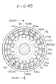
- Fig. 45 and Fig. 46 show a tenth embodiment of this invention.
- a rotary pulse motor of this embodiment is of the outer-rotor type.
- Teeth 100 a , 100 a , ------ and slit-like grooves 100 b , 100 b ,------ are alternately formed at a pitch of P/2 in an inner periphery of a cylindrical rotor 100 made of magnetic material.
- Permanent magnets 101, 101, ------ are so inserted into the slit-like grooves 100 b , 100 b , ------ that the teeth 100 a , 100 a ------are magnetized alternately in opposite polarities.
- a cylindrical stator 180 inserted concentrically into the cylindrical rotor 100 consists of a first iron core 103 and a second iron core 104.
- Two rows of magnetic poles 103Aa to 103Ja and 103Ab to 103Jb are formed at an angular regular pitch of P in a periphery of the first iron core 103.
- An annular coil 105 is inserted in an annular groove made between the two rows, as shown in Fig. 46.
- Two rows of magnetic poles 104Aa to 104Ja and 104Ab to 104Jb are formed at an angular regular pitch of P in a periphery of the second iron core 104.
- An annular coil 106 is inserted in an annular groove made between the two rows, as shown in Fig. 46.
- the one row of magnetic poles 103Aa to 103Ja is shifted by a pitch of P from the other row of magnetic poles 103Ab to 103Jb in the first iron core 103.
- the pitch P corresponds to 360 degrees.
- the one row of magnetic poles 104Aa to 104Ja is shifted by a pitch of P from the other row of magnetic poles 104Ab to 104Jb in the second iron core 104.
- the pitch P corresponds to 360 degrees.
- the inductive teeth or magnetic poles 103Aa to 103Ja of the first iron core 103 is shifted by a pitch of P/2 from the inductive teeth or magnetic poles 104Ab to 104Jb of the second iron core 104.
- the pulse currents are supplied to the coils by the two-phase excitation method in the above embodiment.
- alternating currentsIa and Ib as shown in Fig. 10, which are different by 90 degrees in phase from each other, may be supplied to the coils.
- the alternating currents Ia and Ib for A-phase and B-phase may be supplied to the terminals Ta, and Tb, and Tc and Td, respectively.
- Three-phase alternating currents which are different by 120 degrees in phase from one another, may be used for the three-phase excitation.
- a sensor may be provided on the stator (primary) so as to detect a relative movement to the rotor (secondary).
- the rotary pulse motor can be used as servo-motor.
- the sensor is provided on the cylindrical stator 40 to detect the relative movement of the rotor 41, in the first embodiment of Fig. 7.
- the one row of magnetic poles 64Aa to 64Ha is shifted by P/2 from the other row of the magnetic poles 64Ab to 64Hb, and the rotary pulse motor is of the one-phase. They are formed on the one iron core 64.
- pulral (n: integral number) cores may be arranged in the axial direction.
- the magnetic poles on the cores are shifted by P/n (n-phase) in a peripheral direction from those on the adjacent ones.
- the stator includes the first core 82 and the second core 84. It is of the two-phase type. Insteads, plural (n: integral number) cores may be arranged in the axial direction. The magnetic poles on the cores are shifted by P/n (n-phase) in a peripheral direction from those on the adjacent ones.
- the rotor 41 (secondary) is inserted concentrically into the stator 40 (primary).
- the stator and the rotor may be substituted with each other.
- the outer cylindrical member 40 is rotatably supported, and the inner cylindrical member 41 is stationary.
- the surfaces of the magnetic poles and teeth are flat, facing to each other.
- Skew or inclined groove may be made in the surfaces of the magnetic poles or teeth, in order to improve the torque characteristics.
- the stator 50 consists of the first and second iron cores 54 and 56, and the coils 55 and 57 are wound on them.
- the rotary pulse motor of the fourth embodiment is of the two-phase type.
- the number of the iron cores may be larger.
- the phase difference is equal to P/3.
- the phase difference is equal to P/5.
- n integrated number
- the phase difference is equal to P/n, although it is equal to P/4 in the fourth embodiment.
- the stator 91 consists of the first and second iron cores 92 and 93, and the coils 96 and 97 are wound on them.
- the rotary pulse motor of the ninth embodiment is of the two-phase type.
- the number of the iron cores may be larger. When it is three (three-phase), the phase difference between the iron cores is equal to P/3. When it is five (five-phase), the phase difference between the iron cores is equal to P/5. And when it is n (integral number), the phase difference between the iron cores is equal to P/n, although it is equal to P/4 in the ninth embodiment. In that case, the number of the core sections (94 and 95 in the ninth embodiment) is increased in accordance with the number of the iron cores.
Landscapes
- Engineering & Computer Science (AREA)
- Power Engineering (AREA)
- Linear Motors (AREA)
Applications Claiming Priority (9)
| Application Number | Priority Date | Filing Date | Title |
|---|---|---|---|
| JP109420/91 | 1991-05-14 | ||
| JP3109420A JP2682262B2 (ja) | 1991-05-14 | 1991-05-14 | 回転型パルスモータ |
| JP143945/91 | 1991-05-20 | ||
| JP3143946A JP2730326B2 (ja) | 1991-05-20 | 1991-05-20 | 回転型パルスモータ |
| JP1991045148U JP2566791Y2 (ja) | 1991-05-20 | 1991-05-20 | 回転型パルスモータ |
| JP3143945A JP2730325B2 (ja) | 1991-05-20 | 1991-05-20 | 回転型パルスモータ |
| JP143946/91 | 1991-05-20 | ||
| JP45148/91 | 1991-05-20 | ||
| US07/882,472 US5334894A (en) | 1991-05-14 | 1992-05-13 | Rotary pulse motor |
Publications (3)
| Publication Number | Publication Date |
|---|---|
| EP0514176A2 true EP0514176A2 (de) | 1992-11-19 |
| EP0514176A3 EP0514176A3 (en) | 1993-09-22 |
| EP0514176B1 EP0514176B1 (de) | 1996-07-17 |
Family
ID=27522450
Family Applications (1)
| Application Number | Title | Priority Date | Filing Date |
|---|---|---|---|
| EP92304367A Expired - Lifetime EP0514176B1 (de) | 1991-05-14 | 1992-05-14 | Schrittmotor |
Country Status (2)
| Country | Link |
|---|---|
| US (1) | US5334894A (de) |
| EP (1) | EP0514176B1 (de) |
Cited By (6)
| Publication number | Priority date | Publication date | Assignee | Title |
|---|---|---|---|---|
| EP0669699A1 (de) * | 1994-02-23 | 1995-08-30 | FICHTEL & SACHS AG | Rotatorische elektrische Maschine |
| EP0677914A1 (de) * | 1994-04-15 | 1995-10-18 | Herbert Prof. Dr. Weh | Transversalflussmaschine |
| EP1187302A2 (de) * | 2000-07-28 | 2002-03-13 | Japan Servo Co. Ltd. | Motorisch angetriebenes System mit verzahnten Statorpolen |
| EP1276212A2 (de) * | 2001-07-11 | 2003-01-15 | Siemens Aktiengesellschaft | Synchronmaschine |
| DE10217804A1 (de) * | 2002-04-22 | 2003-11-06 | Joern-Heinrich Schaefertoens | Elektrische Synchronmaschine mit Rotoren in Sammlerbauweise und Statoren mit Konzentratorwirkung |
| AT504029B1 (de) * | 2000-07-31 | 2008-10-15 | Acc Germany Gmbh | Elektrische maschine mit einem am maschinengehäuse befestigten steckergehäuse |
Families Citing this family (17)
| Publication number | Priority date | Publication date | Assignee | Title |
|---|---|---|---|---|
| US5514922A (en) * | 1993-02-08 | 1996-05-07 | Sanden Corporation | Hermetic motor driven fluid apparatus having improved insulating structure |
| JP2740893B2 (ja) * | 1993-11-01 | 1998-04-15 | 日本サーボ株式会社 | 永久磁石式ステッピングモータ |
| JP2733824B2 (ja) * | 1995-04-19 | 1998-03-30 | 日本サーボ株式会社 | 2相式永久磁石回転電機 |
| US5959382A (en) * | 1995-10-13 | 1999-09-28 | Milli Sensor Systems And Actuators, Inc. | Magnetic actuator and position control system |
| JP3274597B2 (ja) * | 1995-12-28 | 2002-04-15 | ミネベア株式会社 | パルスジェネレータ |
| JP3442636B2 (ja) * | 1998-01-06 | 2003-09-02 | オークマ株式会社 | 永久磁石電動機 |
| US6392370B1 (en) | 2000-01-13 | 2002-05-21 | Bedini Technology, Inc. | Device and method of a back EMF permanent electromagnetic motor generator |
| JP4874474B2 (ja) * | 2001-08-23 | 2012-02-15 | 日本電産コパル株式会社 | ステッピングモータ |
| TWI296875B (en) * | 2002-04-25 | 2008-05-11 | Step motor with multiple stators | |
| JP3973207B2 (ja) * | 2002-08-09 | 2007-09-12 | ヤマハモーターエレクトロニクス株式会社 | 発電機のステータ |
| JP2005073450A (ja) * | 2003-08-27 | 2005-03-17 | Matsushita Electric Ind Co Ltd | モータジェネレータ |
| WO2007112496A1 (en) * | 2006-03-31 | 2007-10-11 | Calix Ltd | System and method for the calcination of minerals |
| DE102009057446B4 (de) * | 2009-12-08 | 2013-11-14 | L-3 Communications Magnet-Motor Gmbh | Elektrische Maschine |
| US10274175B1 (en) | 2018-01-04 | 2019-04-30 | Electronic Theatre Controls, Inc. | Systems and methods for controlling the position of a moving light fixture |
| US20200044497A1 (en) * | 2018-08-06 | 2020-02-06 | GM Global Technology Operations LLC | Electric motor |
| JP7331356B2 (ja) * | 2018-12-14 | 2023-08-23 | Tdk株式会社 | 永久磁石および回転電機 |
| JP7209260B2 (ja) * | 2019-05-08 | 2023-01-20 | パナソニックIpマネジメント株式会社 | 固定子およびモータ |
Citations (4)
| Publication number | Priority date | Publication date | Assignee | Title |
|---|---|---|---|---|
| US2230007A (en) * | 1937-05-11 | 1941-01-28 | Bendix Aviat Corp | Magneto generator |
| JPS6043061A (ja) * | 1983-08-18 | 1985-03-07 | Fujitsu Ltd | 永久磁石モ−タ |
| EP0352189A1 (de) * | 1988-07-20 | 1990-01-24 | Shinko Electric Co. Ltd. | Betätiger der Bauart mit starker magnetischer Schubkraft |
| EP0373987A1 (de) * | 1988-11-22 | 1990-06-20 | Shinko Electric Co. Ltd. | Betätigungsgerät mit starker magnetischer Schiebekraft |
Family Cites Families (11)
| Publication number | Priority date | Publication date | Assignee | Title |
|---|---|---|---|---|
| JPS5484207A (en) * | 1977-12-19 | 1979-07-05 | Oki Electric Ind Co Ltd | Pulse motor |
| DE3249217C2 (de) * | 1981-12-04 | 1986-02-13 | Portescap | Elektrischer Schrittmotor |
| EP0151159A1 (de) * | 1983-07-28 | 1985-08-14 | GROSJEAN, Michel | Mehrphasiger motor mit einem magnetizierten, pro fläche n/2 polpaare aufweisenden läufer |
| NL8402542A (nl) * | 1984-08-20 | 1986-03-17 | Philips Nv | Synchroonmotor. |
| US4739201A (en) * | 1986-07-25 | 1988-04-19 | The Superior Electric Company | Means to reduce harmonic torque in electromagnetic machines |
| DE3790562C2 (de) * | 1986-09-20 | 1992-01-23 | Nippon Telegraph And Telephone Corp., Tokio/Tokyo, Jp | |
| JPS63113476U (de) * | 1987-01-14 | 1988-07-21 | ||
| US5130595A (en) * | 1987-11-23 | 1992-07-14 | Chrysler Corporation | Multiple magnetic paths machine |
| JPH0193979U (de) * | 1987-12-15 | 1989-06-21 | ||
| JPH0759144B2 (ja) * | 1988-11-29 | 1995-06-21 | 神鋼電機株式会社 | パルスモータ |
| JP2650438B2 (ja) * | 1989-10-05 | 1997-09-03 | 神鋼電機株式会社 | パルスモータ |
-
1992
- 1992-05-13 US US07/882,472 patent/US5334894A/en not_active Expired - Lifetime
- 1992-05-14 EP EP92304367A patent/EP0514176B1/de not_active Expired - Lifetime
Patent Citations (4)
| Publication number | Priority date | Publication date | Assignee | Title |
|---|---|---|---|---|
| US2230007A (en) * | 1937-05-11 | 1941-01-28 | Bendix Aviat Corp | Magneto generator |
| JPS6043061A (ja) * | 1983-08-18 | 1985-03-07 | Fujitsu Ltd | 永久磁石モ−タ |
| EP0352189A1 (de) * | 1988-07-20 | 1990-01-24 | Shinko Electric Co. Ltd. | Betätiger der Bauart mit starker magnetischer Schubkraft |
| EP0373987A1 (de) * | 1988-11-22 | 1990-06-20 | Shinko Electric Co. Ltd. | Betätigungsgerät mit starker magnetischer Schiebekraft |
Non-Patent Citations (4)
| Title |
|---|
| MACHINE DESIGN vol. 57, no. 9, April 1985, CLEVELAND US pages 23 - 29 HORBER 'Higher torque from hybrid stepper motors.' * |
| PATENT ABSTRACTS OF JAPAN vol. 15, no. 330 (E-1103)22 August 1991 & JP-A-31 24 254 ( SHINKO ELECTRIC CO. ) 27 May 1991 * |
| PATENT ABSTRACTS OF JAPAN vol. 9, no. 169 (E-328)(1892) 13 July 1985 & JP-A-60 043 061 ( FUJITSU ) 7 March 1985 * |
| REVUE GENERALE DE L'ELECTRICITE vol. 91, no. 3, March 1981, PARIS FR pages 189 - 196 MAILFERT ET AL 'Étude d'un type de moteur hybride utilisable en fonctionnement pas à pas' * |
Cited By (8)
| Publication number | Priority date | Publication date | Assignee | Title |
|---|---|---|---|---|
| EP0669699A1 (de) * | 1994-02-23 | 1995-08-30 | FICHTEL & SACHS AG | Rotatorische elektrische Maschine |
| EP0677914A1 (de) * | 1994-04-15 | 1995-10-18 | Herbert Prof. Dr. Weh | Transversalflussmaschine |
| EP1187302A2 (de) * | 2000-07-28 | 2002-03-13 | Japan Servo Co. Ltd. | Motorisch angetriebenes System mit verzahnten Statorpolen |
| EP1187302A3 (de) * | 2000-07-28 | 2005-05-04 | Japan Servo Co. Ltd. | Motorisch angetriebenes System mit verzahnten Statorpolen |
| AT504029B1 (de) * | 2000-07-31 | 2008-10-15 | Acc Germany Gmbh | Elektrische maschine mit einem am maschinengehäuse befestigten steckergehäuse |
| EP1276212A2 (de) * | 2001-07-11 | 2003-01-15 | Siemens Aktiengesellschaft | Synchronmaschine |
| EP1276212A3 (de) * | 2001-07-11 | 2005-05-11 | Siemens Aktiengesellschaft | Synchronmaschine |
| DE10217804A1 (de) * | 2002-04-22 | 2003-11-06 | Joern-Heinrich Schaefertoens | Elektrische Synchronmaschine mit Rotoren in Sammlerbauweise und Statoren mit Konzentratorwirkung |
Also Published As
| Publication number | Publication date |
|---|---|
| US5334894A (en) | 1994-08-02 |
| EP0514176B1 (de) | 1996-07-17 |
| EP0514176A3 (en) | 1993-09-22 |
Similar Documents
| Publication | Publication Date | Title |
|---|---|---|
| EP0514176A2 (de) | Schrittmotor | |
| US5128570A (en) | Permanent magnet type stepping motor | |
| US6259176B1 (en) | Multi-phase outer-type PM stepping motor | |
| US4972109A (en) | Stepping motor | |
| US6762526B2 (en) | Multi-phase flat-type PM stepping motor and driving circuit thereof | |
| EP0319096B1 (de) | Linearmotor mit winkelabhängig rastenden Magnetpolen | |
| JP6120563B2 (ja) | モータ駆動装置 | |
| US20090108713A1 (en) | Outer Rotor Type Hybrid Stepping Motor | |
| IE56810B1 (en) | Brushless dc motor | |
| US5629572A (en) | Linear pulse motor | |
| EP2324563B1 (de) | Schrittmotoren des permanentmagnettyps | |
| EP1445851B1 (de) | Motor | |
| EP0183854B1 (de) | Schrittmotor | |
| US6570274B2 (en) | Electric motor | |
| EP0635928B1 (de) | Schrittmotor der hybridischen mehrphasigen bauart und antriebssystem | |
| JP2650438B2 (ja) | パルスモータ | |
| EP0635929B1 (de) | Schrittmotor der hybridischen mehrphasigen bauart und antriebssystem | |
| EP0634831B1 (de) | Schrittmotor der hybridischen mehrphasigen bauart und antriebssystem | |
| JP2730326B2 (ja) | 回転型パルスモータ | |
| JPH0635657Y2 (ja) | ステツピングモ−タ | |
| JP2805640B2 (ja) | ボビン巻電動機 | |
| JPH0635656Y2 (ja) | ステツピングモ−タ | |
| JPH06327223A (ja) | パルスモータ | |
| JPH0312058Y2 (de) | ||
| Dohmeki et al. | Basic characteristics of five‐phase cylindrical linear pulse motors |
Legal Events
| Date | Code | Title | Description |
|---|---|---|---|
| PUAI | Public reference made under article 153(3) epc to a published international application that has entered the european phase |
Free format text: ORIGINAL CODE: 0009012 |
|
| AK | Designated contracting states |
Kind code of ref document: A2 Designated state(s): DE FR GB |
|
| 17P | Request for examination filed |
Effective date: 19930507 |
|
| PUAL | Search report despatched |
Free format text: ORIGINAL CODE: 0009013 |
|
| AK | Designated contracting states |
Kind code of ref document: A3 Designated state(s): DE FR GB |
|
| 17Q | First examination report despatched |
Effective date: 19941013 |
|
| GRAH | Despatch of communication of intention to grant a patent |
Free format text: ORIGINAL CODE: EPIDOS IGRA |
|
| GRAH | Despatch of communication of intention to grant a patent |
Free format text: ORIGINAL CODE: EPIDOS IGRA |
|
| GRAA | (expected) grant |
Free format text: ORIGINAL CODE: 0009210 |
|
| AK | Designated contracting states |
Kind code of ref document: B1 Designated state(s): DE FR GB |
|
| REF | Corresponds to: |
Ref document number: 69212226 Country of ref document: DE Date of ref document: 19960822 |
|
| ET | Fr: translation filed | ||
| PLBE | No opposition filed within time limit |
Free format text: ORIGINAL CODE: 0009261 |
|
| STAA | Information on the status of an ep patent application or granted ep patent |
Free format text: STATUS: NO OPPOSITION FILED WITHIN TIME LIMIT |
|
| 26N | No opposition filed | ||
| REG | Reference to a national code |
Ref country code: GB Ref legal event code: IF02 |
|
| PGFP | Annual fee paid to national office [announced via postgrant information from national office to epo] |
Ref country code: FR Payment date: 20110523 Year of fee payment: 20 |
|
| PGFP | Annual fee paid to national office [announced via postgrant information from national office to epo] |
Ref country code: GB Payment date: 20110511 Year of fee payment: 20 |
|
| PGFP | Annual fee paid to national office [announced via postgrant information from national office to epo] |
Ref country code: DE Payment date: 20110511 Year of fee payment: 20 |
|
| REG | Reference to a national code |
Ref country code: DE Ref legal event code: R071 Ref document number: 69212226 Country of ref document: DE |
|
| REG | Reference to a national code |
Ref country code: DE Ref legal event code: R071 Ref document number: 69212226 Country of ref document: DE |
|
| REG | Reference to a national code |
Ref country code: GB Ref legal event code: PE20 Expiry date: 20120513 |
|
| PG25 | Lapsed in a contracting state [announced via postgrant information from national office to epo] |
Ref country code: DE Free format text: LAPSE BECAUSE OF EXPIRATION OF PROTECTION Effective date: 20120515 |
|
| PG25 | Lapsed in a contracting state [announced via postgrant information from national office to epo] |
Ref country code: GB Free format text: LAPSE BECAUSE OF EXPIRATION OF PROTECTION Effective date: 20120513 |