EP0510336B1 - Méthode pour contrôler sans contact le sens de rotation des machines électriques - Google Patents
Méthode pour contrôler sans contact le sens de rotation des machines électriques Download PDFInfo
- Publication number
- EP0510336B1 EP0510336B1 EP92103855A EP92103855A EP0510336B1 EP 0510336 B1 EP0510336 B1 EP 0510336B1 EP 92103855 A EP92103855 A EP 92103855A EP 92103855 A EP92103855 A EP 92103855A EP 0510336 B1 EP0510336 B1 EP 0510336B1
- Authority
- EP
- European Patent Office
- Prior art keywords
- machine
- sensors
- sense
- rotation
- signals
- Prior art date
- Legal status (The legal status is an assumption and is not a legal conclusion. Google has not performed a legal analysis and makes no representation as to the accuracy of the status listed.)
- Expired - Lifetime
Links
Images


Classifications
-
- G—PHYSICS
- G01—MEASURING; TESTING
- G01P—MEASURING LINEAR OR ANGULAR SPEED, ACCELERATION, DECELERATION, OR SHOCK; INDICATING PRESENCE, ABSENCE, OR DIRECTION, OF MOVEMENT
- G01P13/00—Indicating or recording presence, absence, or direction, of movement
- G01P13/02—Indicating direction only, e.g. by weather vane
- G01P13/04—Indicating positive or negative direction of a linear movement or clockwise or anti-clockwise direction of a rotational movement
-
- G—PHYSICS
- G01—MEASURING; TESTING
- G01B—MEASURING LENGTH, THICKNESS OR SIMILAR LINEAR DIMENSIONS; MEASURING ANGLES; MEASURING AREAS; MEASURING IRREGULARITIES OF SURFACES OR CONTOURS
- G01B7/00—Measuring arrangements characterised by the use of electric or magnetic techniques
- G01B7/30—Measuring arrangements characterised by the use of electric or magnetic techniques for measuring angles or tapers; for testing the alignment of axes
Definitions
- the invention relates to a method and a device for contactless control of the direction of rotation of the rotor of an electrical machine which is surrounded by a machine housing.
- the object of the invention is to propose a method which, with simple construction and handling, enables quick and reliable detection of the direction of rotation of the motor and the running of the motor. At the same time, a device for carrying out this method is to be specified.
- This object is achieved according to the invention in a method of the type mentioned at the outset in that the course of the magnetic stray field generated by the machine through on the outside of the machine housing in the region of the electromagnetic and / or magnetic coupling device between the stator and the rotor, with respect to the machine axis, radially offset sensors by an angular amount are detected, the phase-shifted, mutually identical measurement signals are fed to an evaluation circuit which, as an indication of the direction of rotation of the machine, outputs an output signal corresponding to the sign of the phase shift.
- the sensors can be attached to the outside of the machine housing. This enables a quick and uncomplicated measurement of the direction of rotation to be carried out.
- the method according to the invention is suitable both for mobile use in the maintenance service and for a stationary device for checking the speed and direction of rotation of an electrical machine.
- a reliable statement about the direction of rotation can be made when the course of the magnetic field generated by the machine is detected by two sensors.
- the object is achieved in that the sensors for detecting the course of the machine generated magnetic stray field of the electromagnetically sensitive sensors, in particular Hall sensors, which are offset by an angular amount on the outside of the machine housing in the region of the electromagnetic and / or magnetic coupling device between the stator and the rotor can be fastened and are connected to an evaluation circuit which, as an indication of the direction of rotation of the machine, outputs an output signal corresponding to the sign of the phase shift of the signals from the sensors.
- the sensors for detecting the course of the machine generated magnetic stray field of the electromagnetically sensitive sensors in particular Hall sensors, which are offset by an angular amount on the outside of the machine housing in the region of the electromagnetic and / or magnetic coupling device between the stator and the rotor can be fastened and are connected to an evaluation circuit which, as an indication of the direction of rotation of the machine, outputs an output signal corresponding to the sign of the phase shift of the signals from the sensors.
- the direction of rotation of the machine can be determined particularly easily if the evaluation circuit has a display instrument for the positive and a display element for the negative direction of rotation of the machine. It is particularly advantageous if the display instruments are lights, in particular light-emitting diodes.
- the signals of the electromagnetically sensitive sensors can advantageously be evaluated by an evaluation circuit, the preamplifiers for amplifying the sensor signals, bandpass filters for filtering out undesired interference frequencies, analog-digital converter circuits, in particular Schmitt triggers, for converting the analog to digital signals and comparators for determining the Sign of the phase shift.
- an evaluation circuit can also be microprocessor-controlled.
- bandpass filter it is possible to filter out unwanted interference frequencies and only the fundamental frequency, e.g. 50 Hz of the motor stray field.
- the use of bandpasses is particularly advantageous for converter-controlled or phase-controlled machines with a high harmonic content in the machine current.
- the device according to the invention can be part of a stationary device for monitoring all operating parameters of a machine, in particular an electric motor for a pump or a fan. It is also possible to make the device portable for maintenance and service shape. In this case it makes sense if the device is powered by an accumulator.
- the measurement data can be forwarded particularly easily to a control device if the device has a digital interface for connecting a control device.
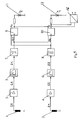
- the device for detecting the direction of rotation of a motor has sensors 1, 2, for example coils or Hall elements, operational amplifiers 3, 4, bandpasses 5, 6, Schmitt trigger circuits 7, 8, phase comparators 9, 10, light-emitting diodes 11, 12 and a digital one Interface 16 on.
- the sensors 1, 2 are radially offset from one another by an angular amount ⁇ m on a plane arranged normal to the motor axis (M), for example on the end face 13 opposite the bushing of the motor shaft or on the lateral surface 14 of the motor housing 15 enveloping the motor.
- the electromagnetic stray field Bm of the motor is induced in the sensors 1, 2, which deliver a corresponding signal S1, S2, which has a cosine curve.
- the signals S1, S2 are out of phase by an angle ⁇ eL .
- the signals S1, S2 are preamplified by the operational amplifier 3.4. Bandpasses 5, 6 only allow the 50 Hz fundamental frequency of the motor field to pass.
- the Schmitt trigger circuits 7, 8 subsequently convert the analog voltages into digital signals.
- An edge-triggered D flip-flop is used as the phase comparator 9, 10, which outputs output signals Q 1, Q 2 as a function of the phase shift ⁇ eL . If the value of the phase shift ⁇ eL is positive, as is the case when the motor runs clockwise, the output signal Q 1 is at a high level and the LED 11 lights up. On the other hand, if the phase shift ⁇ m is negative, the output signal Q2 is high and the LED 12 lights up.
- the measurement data generated in this way are simultaneously present on the digital interface 16 to which a control device can be connected.
Landscapes
- Physics & Mathematics (AREA)
- General Physics & Mathematics (AREA)
- Control Of Motors That Do Not Use Commutators (AREA)
- Control Of Ac Motors In General (AREA)
- Control Of Electric Motors In General (AREA)
- Indicating Or Recording The Presence, Absence, Or Direction Of Movement (AREA)
Claims (10)
- Procédé pour le contrôle sans contact du sens de rotation du rotor d'une machine électrique qui est entourée par un carter de machine,
caractérisé en ce qu'on détecte l'écoulement du champ de fuite magnétique engendré par la machine, par des capteurs (1, 2) disposés sur la face extérieure du carter de machine dans la zone du dispositif de couplage électromagnétique et/ou magnétique entre stator et rotor, décalés radialement, par rapport à l'axe (M) de machine, d'une valeur d'angle, capteurs dont les signaux de mesure (S1, S2) décalés en phase et égaux entre eux, sont amenés à un circuit d'évaluation qui émet, en tant qu'indication du sens de rotation de la machine, un signal de sortie (Q1, Q2) correspondant au sens du décalage de phase. - Procédé selon la revendication 1,
caractérisé en ce que l'écoulement du champ de fuite magnétique engendré par la machine est détecté par deux capteurs (1, 2). - Dispositif pour la mise en oeuvre du procédé selon l'une des revendication 1 et 2,
caractérisé en ce que les capteurs (1, 2) pour détecter l'écoulement du champ de fuite magnétique engendré par la machine sont des capteurs électromagnétiquement sensibles (1, 2), en particulier des capteurs à effet Hall, qui peuvent être fixés à une valeur d'angle (βM) au carter de machine sur sa face extérieure dans la zone du dispositif de couplage électromagnétique et/ou magnétique entre stator et rotor et sont reliés à un circuit d'évaluation qui émet, en tant qu'indication du sens de rotation de la machine, un signal de sortie (Q1, Q2) correspondant au sens des signaux de mesure (S1, S2) des capteurs (1, 2). - Dispositif selon la revendication 3,
caractérisé en ce que le circuit d'évaluation présente respectivement un instrument d'affichage pour le sens de rotation positif de la machine et un élément d'affichage pour le sens négatif. - Dispositif selon la revendication 3 ou 4,
caractérisé en ce que les instruments d'affichage sont des lampes, en particulier des diodes lumineuses (11, 12). - Dispositif selon l'une des revendications 3 à 5,
caractérisé en ce que le circuit d'évaluation présente des préamplificateurs (3, 4) pour l'amplification des signaux des capteurs, des passe-bandes (5, 6) pour l'extraction par filtration de fréquences perturbatrices non souhaitées, des circuits convertisseurs analogique-numérique (7, 8), en particulier des bascules de Schmitt, pour la conversion des signaux analogiques en numériques et des comparateurs (9, 10) pour déterminer le sens du décalage de phase. - Dispositif selon l'une des revendications 3 à 6,
caractérisé en ce que le circuit d'évaluation est commandé par microprocesseur. - Dispositif selon l'une des revendications 3 à 7,
caractérisé en ce que le dispositif est une partie d'un dispositif pour la surveillance de tous les paramètres d'exploitation d'une machine, en particulier d'un moteur électrique pour une pompe ou un ventilateur. - Dispositif selon l'une des revendications 3 à 8,
caractérisé en ce que le dispositif est portable et est alimenté par un accumulateur. - Dispositif selon l'une des revendications 3 à 9,
caractérisé en ce que le dispositif présente une interface numérique (16) pour le raccordement d'un appareil de réglage.
Applications Claiming Priority (2)
| Application Number | Priority Date | Filing Date | Title |
|---|---|---|---|
| DE4113201A DE4113201A1 (de) | 1991-04-23 | 1991-04-23 | Verfahren zur beruehrungslosen kontrolle der drehrichtung elektrischer maschinen |
| DE4113201 | 1991-04-23 |
Publications (3)
| Publication Number | Publication Date |
|---|---|
| EP0510336A2 EP0510336A2 (fr) | 1992-10-28 |
| EP0510336A3 EP0510336A3 (en) | 1993-02-24 |
| EP0510336B1 true EP0510336B1 (fr) | 1995-07-12 |
Family
ID=6430163
Family Applications (1)
| Application Number | Title | Priority Date | Filing Date |
|---|---|---|---|
| EP92103855A Expired - Lifetime EP0510336B1 (fr) | 1991-04-23 | 1992-03-06 | Méthode pour contrôler sans contact le sens de rotation des machines électriques |
Country Status (3)
| Country | Link |
|---|---|
| EP (1) | EP0510336B1 (fr) |
| AT (1) | ATE125035T1 (fr) |
| DE (2) | DE4113201A1 (fr) |
Cited By (2)
| Publication number | Priority date | Publication date | Assignee | Title |
|---|---|---|---|---|
| DE202011002402U1 (de) | 2011-02-04 | 2012-05-07 | Dr. Fritz Faulhaber Gmbh & Co. Kg | Elektrischer Kleinstmotor |
| EP2485374A1 (fr) | 2011-02-04 | 2012-08-08 | Dr. Fritz Faulhaber GmbH & Co. KG | Moteur électrique miniature |
Families Citing this family (3)
| Publication number | Priority date | Publication date | Assignee | Title |
|---|---|---|---|---|
| DE9302758U1 (de) * | 1993-02-25 | 1994-03-31 | Siemens Ag | Magnetischer Winkellage- und Drehgeschwindigkeitsgeber |
| EP1580561A1 (fr) * | 2004-03-24 | 2005-09-28 | Alcatel | Procede et dispositif pour la détermination de la direction de mouvement avec tolérance aux erreurs |
| DE102010021186A1 (de) * | 2010-05-21 | 2011-11-24 | Michael Sauer | Verfahren zur Drehzahlerfassung und ein Drehzahlerfassungssystem |
Family Cites Families (21)
| Publication number | Priority date | Publication date | Assignee | Title |
|---|---|---|---|---|
| GB1470247A (en) * | 1974-07-08 | 1977-04-14 | British Nuclear Fuels Ltd | Devices for indicating direction of rotation |
| DE2657154A1 (de) * | 1976-12-16 | 1978-10-05 | Charles J Cain | Einrichtung zur fernbestimmung der winkellage, geschwindigkeit und/ oder drehrichtung von drehkoerpern |
| SU742797A1 (ru) * | 1978-04-10 | 1980-06-25 | Предприятие П/Я В-2769 | Устройство дл контрол направлени вращени |
| JPS54148578A (en) * | 1978-04-18 | 1979-11-20 | Nec Corp | Rotating direction detector |
| DE2820122A1 (de) * | 1978-05-09 | 1979-11-15 | Bosch Gmbh Robert | Einrichtung zur drehrichtungserfassung eines rotierenden teiles |
| SE420954B (sv) * | 1979-06-07 | 1981-11-09 | Hans Andersson | Anordning for overvakning av rotationsriktningen hos ett roterbart element |
| JPS5619759U (fr) * | 1979-07-25 | 1981-02-21 | ||
| JPS57169611A (en) * | 1981-04-13 | 1982-10-19 | Tokyo Optical Co Ltd | Measuring device for angular displacement |
| DE3153324C2 (de) * | 1981-11-13 | 1986-10-23 | AEG-Kanis Turbinenfabrik GmbH, 8500 Nürnberg | Digitale Überwachungsanordnung für nacheinander auftretende, aus der Bewegung eines Objektes abgeleitete Impulse von Impulsgebern |
| DE3318351C2 (de) * | 1983-05-20 | 1986-05-22 | Preh, Elektrofeinmechanische Werke Jakob Preh Nachf. Gmbh & Co, 8740 Bad Neustadt | Schaltungsanordnung für eine drehzahl- und drehrichtungsabhängige Auswerteschaltung eines inkrementalen Drehrichtungsimpulsgebers |
| DE3326477A1 (de) * | 1983-07-22 | 1985-01-31 | Telefunken electronic GmbH, 7100 Heilbronn | Anordnung zur bestimmung der drehzahl, der drehrichtung und/oder des drehwinkels eines gegenstandes |
| DE8336769U1 (de) * | 1983-12-22 | 1984-04-26 | C. & E. Fein Gmbh & Co, 7000 Stuttgart | Elektrohandwerkzeug mit einer Umschaltvorrichtung für Rechts- und Linkslauf |
| DD223827A1 (de) * | 1984-05-24 | 1985-06-19 | Goerlitzer Maschinenbau Veb | Schaltungsanordnung zum feststellen der drehrichtung einer maschine, insbesondere turbomaschine |
| DE3428844A1 (de) * | 1984-08-04 | 1986-02-13 | Licentia Patent-Verwaltungs-Gmbh, 6000 Frankfurt | Verfahren zum ermitteln der bewegungsrichtung eines koerpers |
| DE3511623A1 (de) * | 1985-03-29 | 1986-10-09 | Siemens AG, 1000 Berlin und 8000 München | Richtungs- und positionsdetektor |
| US4710683A (en) * | 1985-12-05 | 1987-12-01 | Secoh Geiken Inc. | Rotation detecting apparatus |
| GB8531235D0 (en) * | 1985-12-19 | 1986-01-29 | Lucas Ind Plc | Sensing direction of rotation |
| DE3800824A1 (de) * | 1988-01-14 | 1989-07-27 | Standard Elektrik Lorenz Ag | Vorrichtung mit wenigstens einem in einem gehaeuse angeordneten magnetfeldabhaengigen widerstand |
| US5004981A (en) * | 1988-11-18 | 1991-04-02 | Mitsubishi Jidosha Kogyo Kabushiki Kaisha | Detector device for simultaneously detecting both the direction and number of rotations of rotating member |
| JPH03139185A (ja) * | 1989-10-24 | 1991-06-13 | Mita Ind Co Ltd | 回転検出器の異常検出装置 |
| US5248939A (en) * | 1990-02-22 | 1993-09-28 | The Torrington Company | Apparatus for sensing the direction and speed of a steering wheel shaft using hall effect sensors in a detachable sensor mounting |
-
1991
- 1991-04-23 DE DE4113201A patent/DE4113201A1/de not_active Withdrawn
-
1992
- 1992-03-06 AT AT92103855T patent/ATE125035T1/de not_active IP Right Cessation
- 1992-03-06 EP EP92103855A patent/EP0510336B1/fr not_active Expired - Lifetime
- 1992-03-06 DE DE59202845T patent/DE59202845D1/de not_active Expired - Lifetime
Cited By (2)
| Publication number | Priority date | Publication date | Assignee | Title |
|---|---|---|---|---|
| DE202011002402U1 (de) | 2011-02-04 | 2012-05-07 | Dr. Fritz Faulhaber Gmbh & Co. Kg | Elektrischer Kleinstmotor |
| EP2485374A1 (fr) | 2011-02-04 | 2012-08-08 | Dr. Fritz Faulhaber GmbH & Co. KG | Moteur électrique miniature |
Also Published As
| Publication number | Publication date |
|---|---|
| DE59202845D1 (de) | 1995-08-17 |
| DE4113201A1 (de) | 1992-10-29 |
| EP0510336A3 (en) | 1993-02-24 |
| ATE125035T1 (de) | 1995-07-15 |
| EP0510336A2 (fr) | 1992-10-28 |
Similar Documents
| Publication | Publication Date | Title |
|---|---|---|
| DE102009044542B3 (de) | Wälzlager mit einer Sensoreinheit | |
| DE19716985A1 (de) | Vorrichtung zur Ermittlung der Position und/oder Torsion rotierender Wellen | |
| DE19818799A1 (de) | Verfahren und Vorrichtung zum Messen von Winkeln | |
| DE2944033C2 (de) | Meßeinrichtung zur Ermittlung der Drehbewegung eines Drehkörpers | |
| DE19717364C1 (de) | Verfahren zur Erkennung der Drehrichtung eines Rades mittels Hall-Sonden | |
| DE3840532A1 (de) | Verfahren zur induktiven erzeugung eines elektrischen messsignals zur bestimmung des weges und/oder der position im raum und/oder von materialeigenschaften eines pruefkoerpers und nach diesem verfahren aufgebauter naeherungssensor und verwendung desselben als naeherherungsschalter | |
| DE2639047C2 (de) | Anordnung zur Drehzahlmessung | |
| EP0145882A2 (fr) | Equerre électronique sans contact | |
| DE102018213411A1 (de) | Sensorsystem zur Bestimmung einer Temperatur und mindestens einer Rotationseigenschaft eines um mindestens eine Rotationsachse rotierenden Elements | |
| WO1993007496A1 (fr) | Procede servant a mesurer la vitesse d'un element rotatif | |
| DE102019127297A1 (de) | Sensorvorrichtung zur Erfassung der Drehwinkelstellung einer drehbeweglichen Welle sowie Lenkungsanordnung eines Fahrzeugs | |
| EP0510336B1 (fr) | Méthode pour contrôler sans contact le sens de rotation des machines électriques | |
| DE102007060727A1 (de) | Verfahren des Erkennens einer Rotationsposition durch Benutzen eines Hallelementes und eines Hallelement-Drehmelders | |
| DE3017202C2 (de) | Einrichtung zur Ermittlung der Drehzahl eines drehbaren oder der Frequenz eines linear schwingenden Bauteils aus magnetisch permeablem Material | |
| DE10221340A1 (de) | Sensoranordnung zur Detektierung eines Drehwinkels einer Welle | |
| DE3801171C1 (en) | Device for detecting the speed of the shaft of an exhaust gas turbocharger | |
| DE102018213246A1 (de) | Sensorsystem zur Bestimmung mindestens einer Rotationseigenschaft eines rotierenden Elements | |
| DE1936348C3 (de) | Anordnung zur Messung der Drehzahl und Drehrichtung eines Elektromotors mit elektrisch betriebener Motorbremse | |
| DE3834994A1 (de) | Einrichtung zur erfassung der drehzahl einer welle | |
| EP0247567B1 (fr) | Dispositif de mesure d'angle absolu | |
| DE102012016287A1 (de) | Verfahren zum Bestimmen einer Drehposition einer Welle | |
| DE10040385B4 (de) | Drehbewegungserfassungsvorrichtung | |
| DE2543643C3 (de) | Vorrichtung zur Magnetisierung von Dauermagnetsegmenten | |
| DE102018213410A1 (de) | Sensorsystem zur Bestimmung einer Temperatur und mindestens einer Rotationseigenschaft eines um mindestens eine Rotationsachse rotierenden Elements | |
| DE102018213244A1 (de) | Sensorsystem zur Bestimmung mindestens einer Rotationseigenschaft eines rotierenden Elements |
Legal Events
| Date | Code | Title | Description |
|---|---|---|---|
| PUAI | Public reference made under article 153(3) epc to a published international application that has entered the european phase |
Free format text: ORIGINAL CODE: 0009012 |
|
| AK | Designated contracting states |
Kind code of ref document: A2 Designated state(s): AT BE CH DE DK ES FR GB GR IT LI NL PT SE |
|
| PUAL | Search report despatched |
Free format text: ORIGINAL CODE: 0009013 |
|
| AK | Designated contracting states |
Kind code of ref document: A3 Designated state(s): AT BE CH DE DK ES FR GB GR IT LI NL PT SE |
|
| 17P | Request for examination filed |
Effective date: 19930225 |
|
| 17Q | First examination report despatched |
Effective date: 19940331 |
|
| GRAA | (expected) grant |
Free format text: ORIGINAL CODE: 0009210 |
|
| AK | Designated contracting states |
Kind code of ref document: B1 Designated state(s): AT BE CH DE DK ES FR GB GR IT LI NL PT SE |
|
| PG25 | Lapsed in a contracting state [announced via postgrant information from national office to epo] |
Ref country code: NL Free format text: LAPSE BECAUSE OF FAILURE TO SUBMIT A TRANSLATION OF THE DESCRIPTION OR TO PAY THE FEE WITHIN THE PRESCRIBED TIME-LIMIT Effective date: 19950712 Ref country code: ES Free format text: THE PATENT HAS BEEN ANNULLED BY A DECISION OF A NATIONAL AUTHORITY Effective date: 19950712 Ref country code: GR Free format text: LAPSE BECAUSE OF FAILURE TO SUBMIT A TRANSLATION OF THE DESCRIPTION OR TO PAY THE FEE WITHIN THE PRESCRIBED TIME-LIMIT Effective date: 19950712 Ref country code: DK Effective date: 19950712 |
|
| REF | Corresponds to: |
Ref document number: 125035 Country of ref document: AT Date of ref document: 19950715 Kind code of ref document: T |
|
| ET | Fr: translation filed | ||
| REF | Corresponds to: |
Ref document number: 59202845 Country of ref document: DE Date of ref document: 19950817 |
|
| GBT | Gb: translation of ep patent filed (gb section 77(6)(a)/1977) |
Effective date: 19950808 |
|
| ITF | It: translation for a ep patent filed |
Owner name: SOCIETA' ITALIANA BREVETTI S.P.A. |
|
| PG25 | Lapsed in a contracting state [announced via postgrant information from national office to epo] |
Ref country code: PT Effective date: 19951012 Ref country code: SE Effective date: 19951012 |
|
| NLV1 | Nl: lapsed or annulled due to failure to fulfill the requirements of art. 29p and 29m of the patents act | ||
| PG25 | Lapsed in a contracting state [announced via postgrant information from national office to epo] |
Ref country code: AT Effective date: 19960306 |
|
| PLBE | No opposition filed within time limit |
Free format text: ORIGINAL CODE: 0009261 |
|
| STAA | Information on the status of an ep patent application or granted ep patent |
Free format text: STATUS: NO OPPOSITION FILED WITHIN TIME LIMIT |
|
| 26N | No opposition filed | ||
| PGFP | Annual fee paid to national office [announced via postgrant information from national office to epo] |
Ref country code: CH Payment date: 19970227 Year of fee payment: 6 |
|
| PGFP | Annual fee paid to national office [announced via postgrant information from national office to epo] |
Ref country code: GB Payment date: 19970303 Year of fee payment: 6 |
|
| PGFP | Annual fee paid to national office [announced via postgrant information from national office to epo] |
Ref country code: BE Payment date: 19970326 Year of fee payment: 6 |
|
| PG25 | Lapsed in a contracting state [announced via postgrant information from national office to epo] |
Ref country code: GB Free format text: LAPSE BECAUSE OF NON-PAYMENT OF DUE FEES Effective date: 19980306 |
|
| PG25 | Lapsed in a contracting state [announced via postgrant information from national office to epo] |
Ref country code: LI Free format text: LAPSE BECAUSE OF NON-PAYMENT OF DUE FEES Effective date: 19980331 Ref country code: CH Free format text: LAPSE BECAUSE OF NON-PAYMENT OF DUE FEES Effective date: 19980331 Ref country code: BE Free format text: LAPSE BECAUSE OF NON-PAYMENT OF DUE FEES Effective date: 19980331 |
|
| BERE | Be: lapsed |
Owner name: WILO G.M.B.H. Effective date: 19980331 |
|
| GBPC | Gb: european patent ceased through non-payment of renewal fee |
Effective date: 19980306 |
|
| REG | Reference to a national code |
Ref country code: CH Ref legal event code: PL |
|
| PGFP | Annual fee paid to national office [announced via postgrant information from national office to epo] |
Ref country code: IT Payment date: 20110315 Year of fee payment: 20 Ref country code: FR Payment date: 20110317 Year of fee payment: 20 |
|
| PGFP | Annual fee paid to national office [announced via postgrant information from national office to epo] |
Ref country code: DE Payment date: 20110302 Year of fee payment: 20 |
|
| REG | Reference to a national code |
Ref country code: DE Ref legal event code: R071 Ref document number: 59202845 Country of ref document: DE |
|
| REG | Reference to a national code |
Ref country code: DE Ref legal event code: R071 Ref document number: 59202845 Country of ref document: DE |
|
| PG25 | Lapsed in a contracting state [announced via postgrant information from national office to epo] |
Ref country code: DE Free format text: LAPSE BECAUSE OF EXPIRATION OF PROTECTION Effective date: 20120307 |