EP0509700A1 - Fabrication of pressure vessels - Google Patents
Fabrication of pressure vessels Download PDFInfo
- Publication number
- EP0509700A1 EP0509700A1 EP92303053A EP92303053A EP0509700A1 EP 0509700 A1 EP0509700 A1 EP 0509700A1 EP 92303053 A EP92303053 A EP 92303053A EP 92303053 A EP92303053 A EP 92303053A EP 0509700 A1 EP0509700 A1 EP 0509700A1
- Authority
- EP
- European Patent Office
- Prior art keywords
- tube
- cylindrical
- arcuate
- axis
- forming
- Prior art date
- Legal status (The legal status is an assumption and is not a legal conclusion. Google has not performed a legal analysis and makes no representation as to the accuracy of the status listed.)
- Withdrawn
Links
Images


Classifications
-
- B—PERFORMING OPERATIONS; TRANSPORTING
- B21—MECHANICAL METAL-WORKING WITHOUT ESSENTIALLY REMOVING MATERIAL; PUNCHING METAL
- B21D—WORKING OR PROCESSING OF SHEET METAL OR METAL TUBES, RODS OR PROFILES WITHOUT ESSENTIALLY REMOVING MATERIAL; PUNCHING METAL
- B21D51/00—Making hollow objects
-
- B—PERFORMING OPERATIONS; TRANSPORTING
- B21—MECHANICAL METAL-WORKING WITHOUT ESSENTIALLY REMOVING MATERIAL; PUNCHING METAL
- B21D—WORKING OR PROCESSING OF SHEET METAL OR METAL TUBES, RODS OR PROFILES WITHOUT ESSENTIALLY REMOVING MATERIAL; PUNCHING METAL
- B21D51/00—Making hollow objects
- B21D51/16—Making hollow objects characterised by the use of the objects
- B21D51/24—Making hollow objects characterised by the use of the objects high-pressure containers, e.g. boilers, bottles
-
- B—PERFORMING OPERATIONS; TRANSPORTING
- B21—MECHANICAL METAL-WORKING WITHOUT ESSENTIALLY REMOVING MATERIAL; PUNCHING METAL
- B21D—WORKING OR PROCESSING OF SHEET METAL OR METAL TUBES, RODS OR PROFILES WITHOUT ESSENTIALLY REMOVING MATERIAL; PUNCHING METAL
- B21D22/00—Shaping without cutting, by stamping, spinning, or deep-drawing
- B21D22/14—Spinning
- B21D22/18—Spinning using tools guided to produce the required profile
Definitions
- the present invention relates generally to an improved apparatus for the formation and production of cylindrical pressure vessels or tanks through metal spinning operations, and more particularly to an apparatus arranged for the production of double-ended vessels through the simultaneous formation and/or creation of end closures along a hollow, thin-walled cylindrical work tube rotatably supported within the apparatus.
- the apparatus of the present invention is designed to provide and facilitate the rapid production of double-ended pressure vessels whereby the distribution of the wall thickness of the end cap portion of the vessel may be controlled so as to provide a predetermined properly distributed wall thickness which provides zones of increased thickness where desired for durability and improved pressure vessel or tank lifetime or performance.
- pressure vessels or tanks have been typically fabricated from a central tubular cylindrical body portion to which appropriately designed end caps are secured, typically through welding operations.
- Such vessels have, of course, been recognized as being suited for a wide variety of fluid retention applications. Because of the requirement of welding end caps to the cylindrical tube portion, the cost of labor and materials in the production of pressure vessels has been a significant factor in their overall cost of production.
- an apparatus and process which enables the production of double-ended vessels through the simultaneous formation of end closures along a cylindrical work tube, particularly thin-walled tubing. These end closures may also be formed along the pattern and/or design of the commonly accepted and recognized tanks or vessels.
- the apparatus of the present invention is capable of producing tank ends which are consistent with the ASME designs for high crown, elliptical, and standard code ends, as well as non-code standard ends.
- the distribution of wall thickness of the tank ends produced by the apparatus of the present invention may be influenced so as to provide greater thickness at the knuckle area (the zone of smallest radius of curvature) so as to create a vessel with greater durability and extended lifetime.
- a tank end may be formed through a spinning technique wherein the wall thickness in the knuckle zone is made greater than the wall thickness along the remaining portions of the tank.
- the apparatus of the present invention renders it possible to fabricate a pressure vessel or tank by a spinning technique wherein the opposed closed ends are simultaneously formed.
- the availability of such simultaneous treatment significantly reduces the time required for tank fabrication, inasmuch as only one heating-and-cooling cycle is required for the entire end cap fabrication operation. Additionally, the handling normally required is significantly reduced because of the simultaneous end cap formation capability.
- an apparatus which enables the formation and/or production of tank ends through the simultaneous spinning formation of such ends, and wherein the spinning operation utilizes forming rollers at opposed ends which utilize forces which may vary during an axially outwardly radially inwardly directed forming stroke as contrasted with an axially inwardly radially outwardly directed forming stroke.
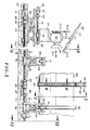
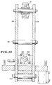
- the apparatus for the production of double-ended vessels generally designated 10 comprises frame means 11 including a primary base mounting pad 12 containing an elongated axial guideway or rail along with a plurality of opposed pairs of guideways including a first pair of opposed guideways 13 and 14, along with a second pair of opposed guideways 16 and 17.
- These guideways are generally equally and oppositely disposed relative to the center of the apparatus 10.
- Each of the guideways 13 and 14 include a series of superimposed or stacked slidable plates, with guideway 13 including slidable plates 13A, 13B and 13C.
- guideway 14 includes slidable plates 14A, 14B and 14C.
- Slidable plates 13A and 14A are movable along an axis transverse to the elongated axis of support 11, while plates 13B, 13C, 14B and 14C are each movable along axes parallel to the elongated axis of support 11.
- pads 13C and 14C may be used for establishing a static set-up dimensional placement for the device, while plates 13B and 14B may be utilized for establishing a fine tuning or dynamic adjustment.
- Heating torch articulating means 18 and 19 are provided at each end of the production apparatus 10, with the torch articulating means 18 and 19 being secured to a first opposed pair of secondary base mounting pads 20 and 21. Means are provided for adjustably securing a heating torch to the articulating means, with heating torches being illustrated as at 22 and 23 respectively.
- secondary base mounting pads 20 and 21 are arranged to support, articulate, and control the programmed movement of the tube forming rollers employed in the spinning operation.
- a flame is shown schematically at 22A and 23A, with these flames being directed toward and impinging directly upon the surface of cylindrical work tube generally designated 24.
- flames emitted from heating torches 22 and 23 impinge upon ends portions 25 and 26 respectively of cylindrical work tube 24.
- cylindrical work tube guide arms 28 and 29 are each secured to a second opposed pair of secondary base mounting pads 16 and 17, with the cylindrical work tube guide means being adapted to adjustably and releasably position the cylindrical work tube 24 within the apparatus 10.
- cylindrical work tube guide means including guide rollers 30 and 31 are arranged to guidingly contact guide ring 32, at spaced arcuate dispositions therealong.
- the guide ring 32 is disposed about the outer periphery of cylindrical work tube 24.
- guideways 13 and 14 are designed for accommodating linear motion along a pair of axes, as illustrated in double-headed arrows 34-34 (Figure 1), along with guideways 35 and 36, also illustrated in Figure 1.
- primary base mounting pad assemblies 13 and 14 are designed to accommodate linear or translatory motion along two axes arranged at right angles, one to the other.
- the heating torch articulating means is illustrated in Figures 1 and 2, particularly with movement available from guideways 34, 35, and 36.
- both the heating torches 22 and 23, along with forming members such as forming rollers 40 and 41 are designed to move along those two axes for the base pads 13 and 14.
- the heating torch articulating means and the forming rollers move as a unit, thereby providing for ease of control of temperature of that portion of the cylindrical work tube 24 being subjected to the metal spinning operation.
- variable speed motors are provided as at 42 and 43, with the motor speed being designed to rotate forming rollers 40 and 41 to provide substantially matching rates of speed between the contacting surfaces of work tube 24 and forming rollers 40 and 41 regardless of radial disposition, thus avoiding galling.
- a belt drive from a remote motor may be employed to rotate forming rollers 40 and 41 at appropriate speeds.
- a belt and pulley arrangement is illustrated in Figure 5, such as at 42A and 43A. Rollers 40 and 41 may be rotated about the vertical axis of member 42 if desired and as indicated in Figure 4.
- guide rollers 30 and 31 are adapted to be adjustably positioned in accordance with the double-ended arrow 46.
- the appropriate working height for work tube 24 is provided.
- the tube axis is moved downwardly and larger diameter work tubes may be introduced into the apparatus and subjected to metal spinning operations therewithin.
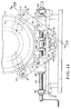
- Tube drive and gripping means are arranged as shown generally at 50, with the work tube drive and gripping means being located or positioned generally intermediate of the production apparatus 10, and between opposed pads 20 and 21.
- Tube drive and gripping means include a hinged guide ring 51 in which there is received a segmented or split spur gear 52.
- Gear 52 may be in the form of an inverted timing belt, and is arranged to mesh with a second gear as at 53.
- Gear 53 may also be an inverted timing belt.
- Hydraulic motor 54 is designed to provide the rotational energy through its output shaft 55 to drive cylinder 56 within which gear 53 is retained.
- Position adjusting means are shown as at 59, with this position adjustment means 59 preferably being in the form of a hydraulic cylinder having a positioning ram as at 60.
- the extension of ram 60 will, of course, determine the position of drive gear or belt retaining cylinder 56.
- Suitable guide and frame means are provided for cylinder 59, as at 61.
- cylinder 56 is journably supported within retaining brackets 62. Cooling means such as water discharge may be used to protect the holdings means 131-131 and 133-133.
- heat for the spinning operation is normally provided through heating torches 22 and 23.
- a single heating torch at each end may prove to be adequate.
- additional heating torches may be provided as at 64-64 and 65-65.
- a supply of gas for the auxiliary torches is further indicated as at 66 and 67.
- gas supply for main heating torches 22 and 23 may be provided as at 68 and 69.
- Cooling means in the form of water spray jets may be positioned adjacent to tank ends for added temperature control.
- Nut 76 is secured to arms 28-28, and rotation of shaft 75 in turn controls the axial disposition of arms 28 and 29 and rollers 30 and 31.
- the opposed end of the system is provided with threaded shafts 77 and 77A together with nut assemblies such as at 78 for controlling the axial disposition of support roll 31 and its mating guide roll on the opposed side of the cylinder 24.
- Shaft 77A (not shown) is utilized in connection with the positioning of pad or plate 14C.
- Guide rolls 30 and 31, together with the corresponding pair of guide rolls (one of which is indicated at 31) adjustably cradle and support the cylinder 24 for controlled rotation about its longitudinal axis.
- hydraulic motor 80 is coupled to threaded shaft 75 through coupling 81.
- Shaft 75 is mounted for rotation within bearing assembly 82, and includes an extension of threaded shaft 75 through aligning member 83.
- a bearing block is indicated at 84 for preventing axial motion in the rotation of shaft 75.
- the opposed end of shaft 75 is received within bearing block 85, and ultimately within coupling assembly generally shown at 86, along with coupling sleeve 87 joining shafts 75 and 77, one to the other.
- a second bearing block is provided for shaft 77 as at 88.
- rotational motion of hydraulic motor 80 causes rotation of oppositely threaded shafts 75 and 77 to occur in unison, thereby controlling and expediting the positioning of guide rolls 31-31, along with its mating rolls 30-30 disposed on the concealed portion of the view of Figure 5.
- a computer controlled operating drive means (not shown) is provided for shaft segment 90 coupled to threaded shaft 91 at coupling member 92.
- Bearing 93 is provided to enable appropriate rotation of shaft 91 and corresponding axial motion of secondary mounting pad 20 through nut assembly 95.
- An additional bearing is provided as at 96 to support the rotation of shaft 91.
- the Y-axis motion (99A) is created through rotation of threaded shaft 99, with rotation of threaded shaft 99 being made possible through shaft extension 100 which is coupled to a motor (not shown).
- Nut assembly 101 is utilized to provide motion directly to mounting plate 102 as indicated in Figure 6. Accordingly, as the threaded shaft 99 is rotated within bearings 104 and 105, nut assembly 101 causes linear motion to occur on mounting plate 102.
- shaft 99 is disposed at right angles to shaft 91, and thus appropriate motion in desired directions may be obtained through controlled rotation of shafts 91 and 99 and their counterparts.
- the oppositely disposed portion mounted upon and coupled to secondary base mounting pad 21 is a mirror image of that arrangement illustrated in Figure 6. In other words, the apparatus is provided with oppositely disposed pairs of metal spinning apparatus.
- Appropriate programmed control may be coupled to the motor means utilized to drive shafts 91 and 99 and their counterparts. See double-ended arrows 91A ( Figure 5) and 99A ( Figure 6) indicating this motion.
- a family of excursions may be designed for forming roller 40. These excursions are designed to perform the necessary metal spinning and formation operations which will ultimately close the end of tube 24, and form a closed end as illustrated in phantom in Figure 1 at 106.
- Frame means 110 includes upper and lower cross-members 110A and 110B.
- Posts 110C-110C are provided with reinforcing gussets, as indicated for example at 110D.
- Appropriate corner braces are provided in order to provide overall stability to frame means 110.
- frame means 110 supports hydraulic cylinder 111 having a slide or ram 112 coupled thereto, with cylinder 111 being, of course, a double-acting cylinder.
- a clevis arrangement 113 Secured to the distal end of slide or ram 112 is a clevis arrangement 113 to which is mounted hydraulic motor 54. Rotation of the output shaft of motor 54, as indicated, drives member 56 which is, in turn, in mesh with gear 52.
- Vertical adjustment is provided by ram 112 in order to accommodate and treat tanks of different diameters.
- Figure 8 illustrates further details of the drive mechanism for rotating the cylindrical work cylinder.
- Hydraulic motor 54 is coupled through coupling element 115 to shaft 116 to which drive member 117 is arranged in fast relationship.
- Appropriate bearings are provided at 118 and 119 to accommodate rotational motion of shaft 116.
- a secondary coupling is provided along shaft 116 as at 120 for obtaining data from encoder 121.
- Encoder 121 is designed to provide position feedback data to the system, and also to provide for controllable rotational motion to the components system, with suitable encoders being, of course, commercially available.
- hydraulic cylinder 111 may be an air cylinder, if desired.
- the motion control means handling the positioning of forming rollers, such as roller 40 are desirably coordinated with the rotational speed of the tank so that lineal rates of motion between the surface of the tank and roller 40 are substantially matching.
- latch system 123 is provided in order to tightly grip drive ring 51 about the outer periphery of cylindrical work tube 24.
- Latch system 123 is coupled on either side of parting line 125 in order to achieve appropriate gripping relationship of ring 51 about tube 24.
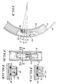
- drive ring 51 utilizes latch member 123 with gripping element 126, and with an arcuate spacing of 5 degrees on either side of the parting line, for example, being designated as appropriate for stable gripping force. The angular relationship is illustrated in Figure 9.
- latch system 123 includes a toggle lever 127 for achieving appropriate closure arrangements.
- Figure 11A illustrates the detail of guide ring 32.
- Guide ring 32 is provided with a channel zone as at 130 to receive roller supports 30-30 and 31-31 therewithin.
- Guide rings 32-32 along with rollers such as at 30-30 and 31-31 complete that portion of the assembly.
- Suitable O-rings are provided, such as at 131 for providing resilient gripping between member 32 and the outer periphery of cylinder tube 24.
- Latching mechanism 123 is illustrated in both Figures 11A and 11B.
- only one guide ring of the type shown in this Figure 11A need be employed, with the second or opposed guide being in the form of a flat ring or short cylinder, without flanges 32A-32A being required to be present.
- it may in certain instances be desirable to utilize a dual set of flanged members such as are illustrated at 32-32 in Figure 1.
- Figure 11B is similar to Figure 11A, but illustrating the detail of drive ring 51.
- Drive ring 51 may be provided with spur gear or timing belt 52 about the outer periphery thereof, with belt 52 being a timing belt with the drive teeth turned out.
- a latch mechanism such as shown generally at 123 is provided in a manner similar to that shown in Figure 9, with a small access hole being cut out of the gear or belt.
- O-rings are provided as at 133-133 to achieve appropriate snug gripping between drive ring 51 and the outer periphery of cylinder tube 24.
- tube 24 may have a diameter ranging from between about 12'' and 30'', with larger or smaller tubes being appropriate as well.
- drive ring 51 along with other support rings, such as ring 32 may be fabricated in a family of rings so as to render it possible to work with tubes of different diameter.
- cylinder 59 may be utilized to both adjustably accommodate the tubes being treated, as well as to maintain a drive force on the surface of the tube so as to achieve constant, predictable, and reliable rotation thereof. Such rotation is, of course, desired in view of the manner in which force is applied to the forming rollers as they move across the metallic work being spun and/or rotated.
- Support rollers 30 and 31 are designed to provide a cradle mechanism for the tube 24, and the arcuate spacing between support rollers 30 and 31 is controlled by a pair of right-hand and left-hand threaded shafts 135 and 136.
- Shafts 135 and 136 are right-hand and left-hand threaded segments respectively, and are joined together at coupling 137.
- Bearing blocks are provided as at 138-138 for shaft segment 135, and at 139-139 for shaft segment 136.
- Nut assemblies are provided as at 140-140 to provide appropriate spacing, and thus angular disposition, with pin retention slots being provided at 141-141 to achieve angular control of arms 28 and 29.
- Figure 13 of the drawings wherein a further view of the details of the system described in Figure 12 are illustrated.
- arm 29 is designed to pivot about its mount 144 and thus achieve appropriate location to provide cradle support for cylindrical work tube 24.
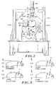
- FIG. 4 Attention is now directed to Figure 4 of the drawings wherein a typical family of curves are provided for illustrating the traversing and/or sweeping routes of travel of cylindrical work tube forming rollers 40 and 41.
- forming roller 40 typically travels about an arcuate path from a point along the outer periphery of tube 24 to the termination of Pass No. 1, where indicated.
- Pass No. 1 is achieved on a 15'' radius, with the motion and other movement of forming roller 40 being achieved by combined and coordinated movement of the X and Y axes control.
- forming roller 40 traverses the path or track identified as Pass No. 2 for return to a position adjacent the outer periphery of tube 24.
- a modified tilt angle for forming roller 40 as about vertical axis 42, this may be achieved as shown in phantom in Figure 4.
- a tilt angle of 10 degrees may, in certain instances, provide enhanced performance of the system.
- liquid coolant for the forming rollers, including forming roller 40.
- Liquid coolant may be interposed into the confines of forming roller 40 so as to achieve cooling as desired.
- suitable rotary couplings are provided in order to preserve the flow of liquid coolant such as water through the interior of the forming rollers, such as forming roller 40.
- a conventional gas torch may be utilized to heat the metal at and along the juncture point, whereupon the metal flows inwardly to seal the tank closure tight.
- the apparatus illustrated and described hereinabove provides a means for achieving formation of tank ends for cylindrical pressure vessels by utilizing the tank material from an original cylindrical tube.
- the sequential excursions or sweeping of the forming rollers as indicated in Figure 4 are undertaken on a basis that the force applied to the forming rollers during a stroke moving axially outwardly may be more or less or equal to that applied during a stroke moving axially inwardly of the tube being treated.
- a substantial portion of the inwardly directed arcuate strokes will be undertaken at a rate which is either greater, less than, or equal to that applied during the axially outwardly directed stroke.
- Rotational rates of speed for the work (tank) may be varied to maintain a substantially matching rate of speed at the forming roller-tank surface interface. Increasing the rotational velocity of the tank as the forming roller 40 moves radially inwardly achieves this result and also increases production rates through a reduction in cycle time.
Landscapes
- Engineering & Computer Science (AREA)
- Mechanical Engineering (AREA)
- Shaping Metal By Deep-Drawing, Or The Like (AREA)
- Forging (AREA)
Applications Claiming Priority (2)
| Application Number | Priority Date | Filing Date | Title |
|---|---|---|---|
| US68762991A | 1991-04-19 | 1991-04-19 | |
| US687629 | 1991-04-19 |
Publications (1)
| Publication Number | Publication Date |
|---|---|
| EP0509700A1 true EP0509700A1 (en) | 1992-10-21 |
Family
ID=24761170
Family Applications (1)
| Application Number | Title | Priority Date | Filing Date |
|---|---|---|---|
| EP92303053A Withdrawn EP0509700A1 (en) | 1991-04-19 | 1992-04-07 | Fabrication of pressure vessels |
Country Status (15)
| Country | Link |
|---|---|
| EP (1) | EP0509700A1 (es) |
| JP (1) | JPH07185681A (es) |
| KR (1) | KR920019441A (es) |
| CN (1) | CN1039524C (es) |
| AU (1) | AU1499692A (es) |
| BR (1) | BR9201402A (es) |
| CA (1) | CA2065538A1 (es) |
| FI (1) | FI921749A (es) |
| GB (1) | GB2256824A (es) |
| IE (1) | IE921244A1 (es) |
| IL (1) | IL101511A0 (es) |
| MX (1) | MX9201738A (es) |
| NO (1) | NO921427L (es) |
| PL (1) | PL294294A1 (es) |
| TW (1) | TW217390B (es) |
Cited By (4)
| Publication number | Priority date | Publication date | Assignee | Title |
|---|---|---|---|---|
| FR2806335A1 (fr) * | 2000-03-14 | 2001-09-21 | Air Liquide | Installation de prechauffage de pieces avant fluotournage, notamment de pieces tubulaires |
| CN102500709A (zh) * | 2011-09-22 | 2012-06-20 | 上海英汇科技发展有限公司 | 将管状类工件两端同时加工成型的方法和系统 |
| CN102615175A (zh) * | 2012-03-12 | 2012-08-01 | 宜兴市联丰化工机械有限公司 | 一种合金封头的加工方法 |
| CN110405094A (zh) * | 2019-08-31 | 2019-11-05 | 远军热能动力科技有限公司 | 一种管材两端缩口加工机床及其加工方法 |
Families Citing this family (14)
| Publication number | Priority date | Publication date | Assignee | Title |
|---|---|---|---|---|
| KR100887395B1 (ko) * | 2007-07-30 | 2009-03-06 | 주식회사 태광에스텍 | 고압용기 제조장치 |
| KR100918612B1 (ko) * | 2007-11-20 | 2009-09-25 | 국방과학연구소 | 후판 용접형 예비성형체를 이용한 유동성형 압력 용기제작 방법 |
| KR100964545B1 (ko) * | 2008-01-08 | 2010-06-21 | 주식회사 삼도인더스트리 | 플로우포밍 성형기를 이용한 알루미늄 휠 제조설비 |
| CN101579582B (zh) * | 2009-06-15 | 2011-10-26 | 重庆钢铁(集团)有限责任公司 | 原液结晶器封头盖与釜体装配工艺方法 |
| TWI424916B (zh) * | 2009-08-14 | 2014-02-01 | Chung Shan Inst Of Science | 厚殼高密度聚乙烯容器製造方法 |
| JP5578910B2 (ja) * | 2010-03-31 | 2014-08-27 | サムテック株式会社 | スピニング加工装置 |
| CN101972808B (zh) * | 2010-10-18 | 2012-02-22 | 哈尔滨工业大学 | 热旋压机独立数控跟随火焰加热装置 |
| KR101496228B1 (ko) * | 2012-09-24 | 2015-02-27 | 안희석 | 축관 성형 장치 및 이를 이용한 축관 성형 방법 |
| BR102014000067A2 (pt) * | 2014-01-03 | 2015-11-17 | Antônio Carlos Torres | reservatório de água fabricado pelo processo de repuxo |
| CN105215632A (zh) * | 2015-09-17 | 2016-01-06 | 芜湖三花制冷配件有限公司 | 一种金属管旋压成型容器的工艺 |
| CN110064694A (zh) * | 2019-05-09 | 2019-07-30 | 浙江长兴和良智能装备有限公司 | 一种旋压系统 |
| CN110252844B (zh) * | 2019-06-11 | 2021-09-21 | 浙江长兴和良智能装备有限公司 | 一种双头旋压系统及双头旋压方法 |
| CN111957796B (zh) * | 2020-08-18 | 2022-04-12 | 东莞市耀晟汽车配件有限公司 | 一种五金模具自动对位装置 |
| CN113305200A (zh) * | 2021-05-13 | 2021-08-27 | 成都陵川特种工业有限责任公司 | 一种液压式旋压机构 |
Citations (6)
| Publication number | Priority date | Publication date | Assignee | Title |
|---|---|---|---|---|
| DE537094C (de) * | 1929-08-09 | 1931-11-02 | Mannesmann Ag | Vorrichtung zur Herstellung von bauchigen Blechgefaessen |
| US2406059A (en) * | 1943-06-10 | 1946-08-20 | Linde Air Prod Co | Process of spinning hollow articles |
| US3496747A (en) * | 1967-09-21 | 1970-02-24 | Nordberg Manufacturing Co | Numerically controlled spinning machine |
| FR2465532A1 (fr) * | 1979-09-24 | 1981-03-27 | Greer Hydraulics Inc | Procede de fabrication de reservoirs de pression par formage a chaud |
| FR2481237A1 (fr) * | 1980-04-29 | 1981-10-30 | Gp Konstruk | Rouleau de convoyeur et procede de fabrication dudit rouleau |
| EP0081700A1 (en) * | 1981-11-20 | 1983-06-22 | Air Products And Chemicals, Inc. | Spin forming |
Family Cites Families (2)
| Publication number | Priority date | Publication date | Assignee | Title |
|---|---|---|---|---|
| GB400067A (en) * | 1932-03-07 | 1933-10-19 | Babcock & Wilcox Ltd | Improvements in the manufacture of pressure vessels |
| DE2144863C3 (de) * | 1971-07-09 | 1975-07-10 | Dalmine S.P.A., Mailand (Italien) | Vorrichtung zum Schließen des Endes eines rohrförmigen Metallwerkstückes |
-
1992
- 1992-04-06 IL IL101511A patent/IL101511A0/xx unknown
- 1992-04-07 EP EP92303053A patent/EP0509700A1/en not_active Withdrawn
- 1992-04-07 CA CA002065538A patent/CA2065538A1/en not_active Abandoned
- 1992-04-10 NO NO92921427A patent/NO921427L/no unknown
- 1992-04-13 KR KR1019920006098A patent/KR920019441A/ko not_active Application Discontinuation
- 1992-04-14 MX MX9201738A patent/MX9201738A/es unknown
- 1992-04-15 BR BR929201402A patent/BR9201402A/pt not_active Application Discontinuation
- 1992-04-16 TW TW081102995A patent/TW217390B/zh active
- 1992-04-16 GB GB9208477A patent/GB2256824A/en not_active Withdrawn
- 1992-04-16 FI FI921749A patent/FI921749A/fi not_active Application Discontinuation
- 1992-04-16 IE IE124492A patent/IE921244A1/en not_active Application Discontinuation
- 1992-04-16 AU AU14996/92A patent/AU1499692A/en not_active Abandoned
- 1992-04-18 CN CN92103687A patent/CN1039524C/zh not_active Expired - Fee Related
- 1992-04-20 JP JP4099611A patent/JPH07185681A/ja active Pending
- 1992-04-21 PL PL29429492A patent/PL294294A1/xx unknown
Patent Citations (6)
| Publication number | Priority date | Publication date | Assignee | Title |
|---|---|---|---|---|
| DE537094C (de) * | 1929-08-09 | 1931-11-02 | Mannesmann Ag | Vorrichtung zur Herstellung von bauchigen Blechgefaessen |
| US2406059A (en) * | 1943-06-10 | 1946-08-20 | Linde Air Prod Co | Process of spinning hollow articles |
| US3496747A (en) * | 1967-09-21 | 1970-02-24 | Nordberg Manufacturing Co | Numerically controlled spinning machine |
| FR2465532A1 (fr) * | 1979-09-24 | 1981-03-27 | Greer Hydraulics Inc | Procede de fabrication de reservoirs de pression par formage a chaud |
| FR2481237A1 (fr) * | 1980-04-29 | 1981-10-30 | Gp Konstruk | Rouleau de convoyeur et procede de fabrication dudit rouleau |
| EP0081700A1 (en) * | 1981-11-20 | 1983-06-22 | Air Products And Chemicals, Inc. | Spin forming |
Cited By (5)
| Publication number | Priority date | Publication date | Assignee | Title |
|---|---|---|---|---|
| FR2806335A1 (fr) * | 2000-03-14 | 2001-09-21 | Air Liquide | Installation de prechauffage de pieces avant fluotournage, notamment de pieces tubulaires |
| CN102500709A (zh) * | 2011-09-22 | 2012-06-20 | 上海英汇科技发展有限公司 | 将管状类工件两端同时加工成型的方法和系统 |
| CN102615175A (zh) * | 2012-03-12 | 2012-08-01 | 宜兴市联丰化工机械有限公司 | 一种合金封头的加工方法 |
| CN110405094A (zh) * | 2019-08-31 | 2019-11-05 | 远军热能动力科技有限公司 | 一种管材两端缩口加工机床及其加工方法 |
| CN110405094B (zh) * | 2019-08-31 | 2024-04-30 | 远军热能动力科技有限公司 | 一种管材两端缩口加工机床及其加工方法 |
Also Published As
| Publication number | Publication date |
|---|---|
| CN1066995A (zh) | 1992-12-16 |
| NO921427D0 (no) | 1992-04-10 |
| FI921749A (fi) | 1992-10-20 |
| KR920019441A (ko) | 1992-11-19 |
| IE921244A1 (en) | 1992-10-21 |
| CA2065538A1 (en) | 1992-10-20 |
| MX9201738A (es) | 1992-10-01 |
| GB9208477D0 (en) | 1992-06-03 |
| TW217390B (es) | 1993-12-11 |
| BR9201402A (pt) | 1992-12-01 |
| CN1039524C (zh) | 1998-08-19 |
| PL294294A1 (en) | 1992-11-30 |
| GB2256824A (en) | 1992-12-23 |
| NO921427L (no) | 1992-10-20 |
| AU1499692A (en) | 1992-10-22 |
| IL101511A0 (en) | 1992-12-30 |
| FI921749A0 (fi) | 1992-04-16 |
| JPH07185681A (ja) | 1995-07-25 |
Similar Documents
| Publication | Publication Date | Title |
|---|---|---|
| EP0509700A1 (en) | Fabrication of pressure vessels | |
| CA2474019C (en) | Method and forming machine for manufacturing a product having various diameters | |
| EP2149409A1 (en) | Manufacturing method, manufacturing apparatus and continuous manufacturing apparatus for bent products | |
| EP1977020B1 (de) | Verfahren zum härten eines einen geschlossenen kurvenzug beschreibenden werkstücks | |
| US3804390A (en) | Apparatus and method for heat-treating large diameter steel pipe | |
| US8863565B2 (en) | Three-dimensionally bending machine, bending-equipment line, and bent product | |
| US5235837A (en) | Fabrication of pressure vessels | |
| US4573289A (en) | Apparatus for superfinishing bearing rollers | |
| CN113423847B (zh) | 使用能量束进行加热的方法和系统 | |
| JP2942121B2 (ja) | シートブランクを成形加工するための方法および装置 | |
| US5104462A (en) | Scanning induction hardening process by using radially moving induction coil | |
| US5433800A (en) | Scanning induction hardening | |
| JPS6281272A (ja) | 蒸気タ−ビンのダイヤフラムを溶接する方法およびそのための溶接装置 | |
| US4951493A (en) | Method and apparatus for making a spiral pipe | |
| US6233991B1 (en) | Apparatus and method for spin forming a tube | |
| CA2081332A1 (en) | Device for delivering a collimated beam such as a laser beam | |
| CA2370780A1 (en) | Method for spin forming a tube | |
| EP0328603B1 (en) | Control of straightness in scanning induction hardening of steel | |
| US5647241A (en) | Rotary upper roll selector | |
| US3812909A (en) | Apparatus for heating and cooling long cylindrical parts | |
| KR100889061B1 (ko) | 피가공물 가공 장치 및 방법 | |
| US4604149A (en) | Process for hardening elongate metal elements | |
| JPH0239564B2 (ja) | Sodetsukibendonetsushorihohooyobisochi | |
| JPS62168617A (ja) | 金属管の曲げ加工装置 | |
| CA1309469C (en) | Scanning induction hardening |
Legal Events
| Date | Code | Title | Description |
|---|---|---|---|
| PUAI | Public reference made under article 153(3) epc to a published international application that has entered the european phase |
Free format text: ORIGINAL CODE: 0009012 |
|
| AK | Designated contracting states |
Kind code of ref document: A1 Designated state(s): AT BE CH DE DK ES FR GB GR IT LI LU NL SE |
|
| STAA | Information on the status of an ep patent application or granted ep patent |
Free format text: STATUS: THE APPLICATION IS DEEMED TO BE WITHDRAWN |
|
| 18D | Application deemed to be withdrawn |
Effective date: 19930422 |