EP0509641A2 - Methode und Apparatur zur Datenaufzeichnung und/oder Wiedergabe - Google Patents
Methode und Apparatur zur Datenaufzeichnung und/oder Wiedergabe Download PDFInfo
- Publication number
- EP0509641A2 EP0509641A2 EP92302294A EP92302294A EP0509641A2 EP 0509641 A2 EP0509641 A2 EP 0509641A2 EP 92302294 A EP92302294 A EP 92302294A EP 92302294 A EP92302294 A EP 92302294A EP 0509641 A2 EP0509641 A2 EP 0509641A2
- Authority
- EP
- European Patent Office
- Prior art keywords
- data
- recording
- track
- recorded
- region
- Prior art date
- Legal status (The legal status is an assumption and is not a legal conclusion. Google has not performed a legal analysis and makes no representation as to the accuracy of the status listed.)
- Granted
Links
Images


Classifications
-
- G—PHYSICS
- G11—INFORMATION STORAGE
- G11B—INFORMATION STORAGE BASED ON RELATIVE MOVEMENT BETWEEN RECORD CARRIER AND TRANSDUCER
- G11B20/00—Signal processing not specific to the method of recording or reproducing; Circuits therefor
- G11B20/10—Digital recording or reproducing
- G11B20/12—Formatting, e.g. arrangement of data block or words on the record carriers
-
- G—PHYSICS
- G11—INFORMATION STORAGE
- G11B—INFORMATION STORAGE BASED ON RELATIVE MOVEMENT BETWEEN RECORD CARRIER AND TRANSDUCER
- G11B20/00—Signal processing not specific to the method of recording or reproducing; Circuits therefor
- G11B20/10—Digital recording or reproducing
- G11B20/18—Error detection or correction; Testing, e.g. of drop-outs
- G11B20/1806—Pulse code modulation systems for audio signals
- G11B20/1809—Pulse code modulation systems for audio signals by interleaving
-
- G—PHYSICS
- G11—INFORMATION STORAGE
- G11B—INFORMATION STORAGE BASED ON RELATIVE MOVEMENT BETWEEN RECORD CARRIER AND TRANSDUCER
- G11B20/00—Signal processing not specific to the method of recording or reproducing; Circuits therefor
- G11B20/10—Digital recording or reproducing
-
- G—PHYSICS
- G11—INFORMATION STORAGE
- G11B—INFORMATION STORAGE BASED ON RELATIVE MOVEMENT BETWEEN RECORD CARRIER AND TRANSDUCER
- G11B20/00—Signal processing not specific to the method of recording or reproducing; Circuits therefor
- G11B20/10—Digital recording or reproducing
- G11B20/12—Formatting, e.g. arrangement of data block or words on the record carriers
- G11B20/1201—Formatting, e.g. arrangement of data block or words on the record carriers on tapes
- G11B20/1207—Formatting, e.g. arrangement of data block or words on the record carriers on tapes with transverse tracks only
- G11B20/1209—Formatting, e.g. arrangement of data block or words on the record carriers on tapes with transverse tracks only for discontinuous data, e.g. digital information signals, computer programme data
-
- G—PHYSICS
- G11—INFORMATION STORAGE
- G11B—INFORMATION STORAGE BASED ON RELATIVE MOVEMENT BETWEEN RECORD CARRIER AND TRANSDUCER
- G11B27/00—Editing; Indexing; Addressing; Timing or synchronising; Monitoring; Measuring tape travel
- G11B27/10—Indexing; Addressing; Timing or synchronising; Measuring tape travel
- G11B27/19—Indexing; Addressing; Timing or synchronising; Measuring tape travel by using information detectable on the record carrier
- G11B27/28—Indexing; Addressing; Timing or synchronising; Measuring tape travel by using information detectable on the record carrier by using information signals recorded by the same method as the main recording
- G11B27/30—Indexing; Addressing; Timing or synchronising; Measuring tape travel by using information detectable on the record carrier by using information signals recorded by the same method as the main recording on the same track as the main recording
- G11B27/3027—Indexing; Addressing; Timing or synchronising; Measuring tape travel by using information detectable on the record carrier by using information signals recorded by the same method as the main recording on the same track as the main recording used signal is digitally coded
- G11B27/3063—Subcodes
-
- G—PHYSICS
- G11—INFORMATION STORAGE
- G11B—INFORMATION STORAGE BASED ON RELATIVE MOVEMENT BETWEEN RECORD CARRIER AND TRANSDUCER
- G11B27/00—Editing; Indexing; Addressing; Timing or synchronising; Monitoring; Measuring tape travel
- G11B27/10—Indexing; Addressing; Timing or synchronising; Measuring tape travel
- G11B27/19—Indexing; Addressing; Timing or synchronising; Measuring tape travel by using information detectable on the record carrier
- G11B27/28—Indexing; Addressing; Timing or synchronising; Measuring tape travel by using information detectable on the record carrier by using information signals recorded by the same method as the main recording
- G11B27/32—Indexing; Addressing; Timing or synchronising; Measuring tape travel by using information detectable on the record carrier by using information signals recorded by the same method as the main recording on separate auxiliary tracks of the same or an auxiliary record carrier
- G11B27/326—Indexing; Addressing; Timing or synchronising; Measuring tape travel by using information detectable on the record carrier by using information signals recorded by the same method as the main recording on separate auxiliary tracks of the same or an auxiliary record carrier used signal is a video-frame or a video-field (P.I.P.)
-
- G—PHYSICS
- G11—INFORMATION STORAGE
- G11B—INFORMATION STORAGE BASED ON RELATIVE MOVEMENT BETWEEN RECORD CARRIER AND TRANSDUCER
- G11B27/00—Editing; Indexing; Addressing; Timing or synchronising; Monitoring; Measuring tape travel
- G11B27/10—Indexing; Addressing; Timing or synchronising; Measuring tape travel
- G11B27/19—Indexing; Addressing; Timing or synchronising; Measuring tape travel by using information detectable on the record carrier
- G11B27/28—Indexing; Addressing; Timing or synchronising; Measuring tape travel by using information detectable on the record carrier by using information signals recorded by the same method as the main recording
- G11B27/32—Indexing; Addressing; Timing or synchronising; Measuring tape travel by using information detectable on the record carrier by using information signals recorded by the same method as the main recording on separate auxiliary tracks of the same or an auxiliary record carrier
- G11B27/327—Table of contents
- G11B27/328—Table of contents on a tape [TTOC]
-
- G—PHYSICS
- G11—INFORMATION STORAGE
- G11B—INFORMATION STORAGE BASED ON RELATIVE MOVEMENT BETWEEN RECORD CARRIER AND TRANSDUCER
- G11B2220/00—Record carriers by type
- G11B2220/90—Tape-like record carriers
Definitions
- This invention relates to a data recording and/or reproducing apparatus and method, and more particularly is suitable for applying to a computer external memory and the like, for example.
- ID-1 format data recorder (ANSI x3.175-1990 19mm Type ID-1 Recorded Instrumentation), wherein recording tracks are formed obliquely in sequence on a magnetic tape, and thus desired data can be recorded and reproduced in high density.
- a magnetic tape 1 is wound on a rotary drum rotating at a predetermined speed, the magnetic tape 1 is run at a predetermined speed, thereby forming recording tracks TR (...TR1, TR2, TR3, TR4, TR1, TR2, 7) obliquely in sequence by the magnetic head mounted on the rotary drum, and thus desired data is recorded on the recording track TR.
- the data recorder forms recording tracks TA, CTL and TC extending longitudinally on both upper and lower ends of the magnetic tape 1, and a track set identification (ID) of the recording tracks TR is recorded on the recording track CTL.
- ID track set identification
- the track set identification is absolute position information beginning from the first of the magnetic tape 1, put between predetermined synchronizing signals, and is recorded at a 4-track period with reference to the recording tracks TR.
- the recording tracks TA and TC are ready for recording user's controlling data and others, thus data recorded in high density on the recording tracks TR can be searched simply by reproducing the recording tracks TA, CTL and TC.
- an error detecting/correcting parity code comprising the so-called product code is applied to record the data concerned, thereby recording and reproducing desired data securely.
- the data recorder After dividing the block into a first field FIELD0 and a second field FIELD1, the data recorder applies Reed-Solomon error detecting/correcting code (comprising C1 code) so as to come orthogonal with the C2 code.
- Reed-Solomon error detecting/correcting code comprising C1 code
- a bit error rate can be enhanced by correcting erroneous reproducing data by means of the C1 and C2 codes in reproducing.
- the data recorder when recording the data DATA with the C1 and C2 codes applied thereto in the magnetic tape 1, interleaving is effected at every recording tracks TR, thus where a drop-out or the like arises, the data DATA can be reproduced securely.
- the data DATA is recorded by changing the inputting order as indicated by arrows b1, b2, ..., bn-1 and bn, thereby interleaving the data DATA.
- a synchronizing signal SYNC and sync block data ID are added at every predetermined unit (hereinafter called sync block), and preamble and postamble data are added as a whole to record the data DATA.
- the synchronizing signal SYNC, the sync block data ID and the data DATA are reproduced on the basis of track sync data included in the preamble, and subjected to deinterleaving on the basis of the synchronizing signal SYNC and the sync block data ID.
- bit error rate can be enhanced to 10 ⁇ 15 or so, then it is conceivable that important data may be safedeposit from applying to a magnetic tape recorder for computer system working, for example, in banks or the like.
- the record data information and the absolute position information TS regarding to the data DATA recorded on the helical record track TR included in the data record region UDA on the magnetic tape 1 are recorded on the helical record track TR of the data management region DITA. As result this, it can be easy to access the data DATA recorded on the helical record track TR of the data record region UDA corresponding to the content of helical record track TR of the data management region DITA.
- the head position of the data management region DITA and the head position of the data record region UDA are previously set by using the absolute position information TS so that it can be immediately to access the data management region DITA and the data record region UDA on the magnetic tape 1 in recording or reproducing.
- a data recording and/or reproducing apparatus for recording and/or reproducing file data DATA which is data composed of one or a plurality of blocks on helical recording tracks TR of a magnetic tape 1 by a file management device 11, comprising: a management information region SCD recording the management information of the file data DATA into the helical record tracks TR of the magnetic tape 1 so as to thereby detect the use of said helical record tracks TR.
- the management information region SCD in which the management information SCD of the file data DATA is recorded. Thereby it can be easy to detect the use of the helical record tracks TR in reproducing.
- a reference numeral 10 denotes a schematic construction of a computer system to which the present invention is applied, wherein write data WR sent from a host computer 11 along with a write request is supplied to a data recorder 13 of ID-1 format as recording data REC through a data recorder control unit 12, and thus the write data WR is written in a recording track on the magnetic tape 1.
- the magnetic tape 1 of the data recorder 13 is reproduced according to a read request inputted from the host computer 11, and reproducing data PB obtained in result is inputted to the host computer 11 as read data RD through the data recorder control unit 12.
- the data recorder control unit 12 comprises a host interface control part 14 and a format control part 15, the host interface control part 14 controls a channel interface against the host computer 11, and the format control part 15 formats data transferred to the data recorder 13 by means of a memory 16.
- control information between the host interface control part 14 and the format control part 15 is transferred by reference to a control table 17.
- the data recorder control unit 12 provided as above is available to using the data recorder 13 as an external memory of the host computer 11 through the interface similar to a conventional magnetic tape recorder on a side of the host computer 11.
- a central portion of the magnetic tape 1 loaded in the data recorder 13 which is comparatively less in damage rate of the tape itself longitudinally is intended for a recording area AREC, thereby enhancing a bit error rate.
- a position 10 [m] behind, for example, from a physical tip PBOT of the magnetic tape 1 is specified as a logical tip LBOT
- a position 15 [m] for example, in front of a physical end PEOT of the magnetic tape 1 is specified as a logical end LEOT
- an area covering the logical tip LBOT to the logical end LEOT is intended for the recording area AREC.
- an area covering the logical tip LBOT to a position 5 [m] behind, for example, therefrom is intended for a directory information track area DITA.
- an area covering the logical end LEOT to an end or around NEOT coming 10 [m], for example, in front thereof across a non-recorded area NRA is intended for user's recording track area UDA, and an area exceeding the end or around NEOT as far as the logical end LEOT is intended for a volume end information area LEOVA.
- a user data area 36,108 [BYTE] per recording track which is specified by ID-1 format is formatted as shown in Figs. 5A and 5B, and the formatted data is interleaved in 4 tracks, thereby enhancing a bit error rate.
- the write data WR from the host computer 11 is recorded as 32,768 [BYTE] recording data DATA comprising 1 block, for example, per recording track with 4 tracks as one set.
- a first supplementary data PD1 is added to be 32,768 [BYTE] as whole. Then, a subcode data SCD for 320 [BYTE] is prepared for loading additional information of the recording track TR.
- C3 code C3 Read-Solomon error detecting/correcting code (hereinafter called C3 code C3 according to the C1 and C2 codes in ID-1 format) is added, as shown in Fig. 5A, by means of a predetermined generator polynomial at every 94 [BYTE] of the subcode data SCD, the recording data DATA or the first supplementary data PD1, an error correction can be carried out more securely thereby, and thus a bit error rate can further be enhanced.
- C3 code C3 Read-Solomon error detecting/correcting code
- the recording data DATA, the first supplementary data PD1 and the C3 code C3 thus formatted per recording track data for four recording tracks TR1, TR2, TR3 and TR4 is interleaved among the tracks according to a predetermined process, thereby enhancing the bit error rate further.
- a second supplementary data PD2 of 204 [BYTE] is added ahead of data for each recording track interleaved for the four recording tracks TR1, TR2, TR3 and TR4, and thus data content for one recording track TR amounts to 36,108 [BYTE] specified by ID-1 format.
- the supplementary data PD2 can be assigned to a magnetic head running-in portion of the recording tracks where the magnetic tape 1 is capable of damaging in most cases and a tracking is not stable, thereby enhancing further the bit error rate for the recording data DATA.
- additional information loaded in the subcode data SCD comprises track classification information TRID indicating a classification of the corresponding recording track TR, a block number BLNO that the recording track TR belongs, a file number FLNO that the recording track TR belongs, a write retry frequency RTCT with reference to the recording tracks and a byte count BYCT of data included in the recording tracks.
- Classification information of volume information table VIT, file information table FIT, update information table UIT, dummy data track information DMY or recording end information EOR is recorded in the track classification information TRID.
- volume information table VIT volume information table VIT, file information table FIT, update information table UIT or dummy data track information DMY is used as the track classification information TRID of the recording track TR formed in the directory information track area DITA of the magnetic tape 1 first.
- the directory information table DIT for managing files on the magnetic tape 1 as a whole is recorded in the directory information track area DITA, and the recording track comprising volume information table VIT is recorded first in a set of four tracks continuously to a 1.5 [m] rise area RUA from the logical tip LBOT of the magnetic tape 1.
- First and final position information of the data block recorded in the user recording track area UDA with the whole magnetic tape 1 as one volume, length information of the file information table FIT and a block number of the data block wherein write retry has been executed in recording are recorded in the recording data DATA of the volume information table VIT.
- the file information table FIT is recorded in 256 tracks continuing to the volume information table VIT.
- a first position information and a block length of the file are recorded in the recording data DATA of the file information table FIT in the unit of file recorded in the user recording track area UDA.
- the dummy data track information DMY is recorded in succession to the file information table FIT in a predetermined track number, and the update information table UIT is recorded in the following four recording tracks.
- Information indicating whether or not updated is recorded in the recording data DATA of the update information table UIT.
- dummy data track information DMY is recorded in the recording track 2.5 [m] from the first of the directory information track are a DITA, and the remaining 2.5 [m] directory information track area DITA is secured as a margin area MGA.
- the user data track information UDT, the tape mark track information TM or the recording end information EOR is used as the track classification information TRID of the recording track TR formed in the user recording track area UDA across the non-recording area NRA in succession to the directory information track area DITA of the magnetic tape 1.
- the recording track TR of the user data track information UDT for a plurality of blocks constructing one file is recorded among the recording tracks TR of the tape mark track information TM with four tracks as one unit as the recording track TR of the user recording track area UDA, and the recording track TR of the recording end information EOR is recorded in succession to the last of the user data track information UDT.
- the first supplementary data PD1 of 32,768 [BYTE] is recorded in the recording data DATA of the tape mark track information TM and the recording end information EOR, and data corresponding to the write data WA inputted from the host computer 11 is recorded in the recording data DATA of the recording track TR of the user recording track area UDA.
- the directory information track area DITA is provided ahead of the magnetic tape 1, and a content of the user recording track area UDA is controlled in files, thus data recorded in the data recorder 13 is accessible like an external recording apparatus viewed from the host computer 11.
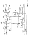
- the format control part 15 of the data recorder control unit 12 in the computer system 10 comprises a recording format portion 20 and a reproducing format portion 40 as shown in Fig. 8 and Fig. 9 along with the memory 16.
- the recording format control portion 20 from inputting data at every 32 bits to a memory (comprising first-in-first-out (FIFO)) circuit 21 from the host interface control part 14 as 4-channel 8-bit parallel write data D0, the write data D0 is synchronized with an internal clock CK, which is written in a buffer memory 22 as input data D1 and sent to a CRC error detection circuit 23.
- a memory comprising first-in-first-out (FIFO) circuit 21 from the host interface control part 14 as 4-channel 8-bit parallel write data D0
- the write data D0 is processed at every 4 channels, however, data for one channel will be referred to for description of the recording format control portion 20.
- the CRC error detection circuit 23 carries out an error detection on the input data D1 by means of CRC (cyclic redundancy code), and inputs a detection result CRCK to a system control circuit 24 in a computer configuration including CPU.
- CRC cyclic redundancy code
- the system control circuit 24 sends it back to the host interface control part 14 as an error detection signal ER.
- the host interface control part 14 executes resending with reference to the write data D0 in which an error is present.
- the buffer memory 22 buffers one recording track TR as described with Figs. 5A and 5B with reference to the input data D1, and sends a first buffer data D2 according to the recording data DATA obtained consequently to a first multiplexer 25.
- a first supplementary data PD1 for the tape mark track information TM sent from a tape mark generation circuit 26 dummy data for the dummy data track information DMY sent from a dummy data generation circuit 27, and the first supplementary data PD1 to the recording data DATA sent from a supplementary data generation circuit 28 are inputted each to the first multiplexer 25.
- the first multiplexer 25 generates a second buffer data D3 by adding the first supplementary data D1 to the recording data DATA of the first buffer data D2 according to a control signal CNT inputted from the system control circuit 24, and sends it to a second multiplexer 29.
- the directory information table DIT sent from a directory information table memory 30, and the subcode data SCD generated in a subcode generation circuit 31 according to a content of the directory information table 30 are inputted to the second multiplexer 29.
- the directory information table DIT described with Fig. 7 is stored in the directory information table memory 30, and the subcode generation circuit 31 generates first and last position information of the data block, length information of the file information table FIT and a block number of the data block having executed rewrite in recording according to a content of the directory information table DIT.
- the second multiplexer 25 forms the format described with Figs. 5A and 5B by adding the subcode data SCD to the second buffer data D3 according to the control signal CNT inputted from the system control circuit 24, and then sends it to a C3 code generation circuit 32 as third buffer data D4.
- the C3 code generation circuit 32 generates the C3 code C3 of 8 [BYTE] to add it to the third buffer data D4, and sends a recording track data D5 obtained consequently to an interleaving circuit 33.
- the interleaving circuit 33 executes interleaving for the four tracks shown in Fig. 6 by loading a recording track data D5 for the four tracks into an interleave memory in sequence and outputting it in the predetermined order, and then sends second recording track data D6 obtained consequently to a third multiplexer 34.
- the second supplementary data PD1 sent from a second supplementary data generation circuit 35, and synchronizing code data sent from a synchronizing code generation circuit 36 are inputted to the third multiplexer 34.
- the third multiplexer 34 adds the second supplementary data PD2 and the synchronizing code data to the second recording track data D6 according to the control signal CNT inputted from the system control circuit 24, and sends a third recording track data D7 thus obtained to a parallel-serial conversion circuit 37.
- the parallel-serial conversion circuit 37 converts the 4-channel 8-bit parallel third recording track data D7 into a serial recorder data S0 for 32 bits, which is inputted to the data recorder 13 as recording data REC through an output circuit 38.
- the recording format control portion 20 of the format control part 15 executes formatting described with Figs. 5A and 5B to Fig. 7 for the write data D0 inputted from the host interface control part 14, generates the recording data REC accordingly, and then records it in the magnetic tape 1 according to ID-1 format as shown in Fig. 1 and Fig. 2.
- a serial reproducing data PB reproduced by the data recorder 13 is inputted to a serial-parallel conversion circuit 41, converted into a 4-channel 8-bit parallel first reproducing data D10, which is inputted to a deinterleaving circuit 42.
- the deinterleaving circuit 42 carries out deinterleaving corresponding to interleaving of the interleaving circuit 33 by loading in the first reproducing data D10 in sequence as in the case of the interleaving circuit 33 of the recording format portion 20 and outputting in the predetermined order, and inputs a second reproducing data D11 obtained consequently to a C3 error correction circuit 43.
- the C3 error correction circuit 43 carries out an error correction for the second reproducing data D11 by means of the C3 code C3 added by the C3 code generation circuit 32 of the recording format portion 20, and sends a third reproducing data D12 thus obtained.
- the first supplement data PD1 included in the third reproducing data D12 is deleted, inputted to a memory circuit 47 as a fourth reproducing data D13 and synchronized with an external clock, and is then sent to the host interface control part 14 as read data D14 outputted from the reproducing format control portion 40.
- the system control circuit 24 sends update information UDD of the directory information table DIT to the data recorder 13 together with a data recorder control signal CDIR, and updates a content of the directory information table DIT on the magnetic tape 1.
- system control circuit 24 sends an answer to the data reproducing request inputted from the host interface control part 14 to the host interface control part 14 as a control signal CHIC together with output data D14.
- the reproducing format control portion 20 of the format control part 15 subjects the reproducing data PB reproduced by the data recorder 13 to formatting counter to the formatting described with Figs. 5A and 5B to Fig. 7, generates the read data D14 and sends it to the host interface control part 14.
- Fig. 8 denotes a record region on the magnetic tape 1 of the embodiment.
- the directory information table region DITA described above in Fig. 2B is predetermined to begin from an absolute position represented by a track set identification value TS, for example "1,000", which is recorded on the control track CTL of the magnetic tape 1, and similarly the user record track region UDA is predetermined to begin from an absolute position of the value TS "10,000".
- control signals sent from the host computer 11 as an instruction are inputted via the host interface control part into the control table 17 and are interpreted by the CPU of the system control circuit 24 of the format control part 15.
- the system control circuit 24 makes ready to take the data into the memory 16, and then takes the write data WR from the host computer 11 into the memory 16 on being ready.
- the system control circuit 24 calculates the data quantity taken into the memory 16, produces the subcode data included the data quantity and the addition information of the block to be recorded and writes the subcode data into the memory of the subcode generation circuit 31.
- the system control circuit 24 instructs to the data recorder 13 a command to begin recording from the predetermined track set identification (here the value TS is "10,000"), and executes the process of recording data.
- the system control circuit 24 writes the contents of the data recorded and the value TS of the track set identification recorded into the memory of the directory information table 30.
- the system control circuit 24 When also the command writing a tape mark from the host computer in addition to the data is inputted, the system control circuit 24 writes the tape mark information into the memory of the directory information table 30, and controls the record format control part 20 to record the tape mark track information on the magnetic tape 1 of the data recorder 13.
- the system control circuit 24 controls data recorder 13 to rewind the magnetic tape 1 by predetermined track set identification (here the value TS is 1,000), transfers the contents of the directory information to the memory 16 for data, record similarly in data recording, and thus the directory information table region DITA of a magnetic tape is formed.
- predetermined track set identification here the value TS is 1,000
- the system control circuit 24 In reproducing the data recorded thus on the magnetic tape 1, the system control circuit 24 reproduces first the directory information table region DITA included in the predetermined track set identification (here the value TS is 1,000), and then takes it in the directory information table memory 46. As the result of this the system control circuit 24 can manage that any kind of data is recorded on the magnetic tape 1.
- the system control circuit 24 reads out the value of the track set identification of the specified block referring to the directory information table memory 46, and controls the data recorder 13 to reproduce the data from the track set read out to the track set corresponding to the predetermined data quantity.
- the addition information and the track set identification being the absolute position information of the record track TR are recorded on the record track TR of the directory information table region DITA, thereby it is realized the data recorder 13 in which it is feasible to access the data recorded on the record track TR of the user record track region UDA according to the content of the record track TR of the directory information table region DITA.
- the front position of the directory information table region DITA and the user record track region UDR is previously set by using the track set identification, thereby it is realized the data recorder 13 in which it is feasible immediately to access the directory information table region DITA and the user record track region UDA of the magnetic tape 1 in recording and reproducing.
- subcode data SCD corresponding to the file management information is recorded on the record tracks TR of the magnetic tape 1, thereby the data recorder 13 can be realized in which the use of the record track is detected corresponding to the content of the subcode data SCD to execute file management.
- the directory information table region DITA and the user record track region UDA on the magnetic tape the absolute positions of which are represented by the track set identification
- an absolute address meant a physical recording track and a corresponding block may be defined on the magnetic tape and recorded on the directory information table region DITA to be manage.
- a region for recording the absolute address ABN, a file size and addition information may be made sure of on the directory information table region DITA in the format control part 15, addition information assigned from the host computer 11 may be respectively recorded to these region and the information of these region may be transferred according to a request from the host computer.
- the data can be managed with a file image by using the magnetic tape, and it can be more easy of use.
- data of every 4 tracks are interleave-processed, however the present invention is not limited thereto, for example, data of every 8 tracks may be interleave-processed.
- the present invention is applied to a external storage device of a computer, however, the present invention may be widely applied to various magnetic recording and/or reproducing apparatuses.
- a frequency of the write retry process that the write retry circuit carries out is not particularly limited, however, a limit of, for example, ten times or so will be provided instead, and in case the write retry frequency in the subcode data exceeds the limit, a message such as "unable to record” or the like may be applied to the recording data and so transmitted to the host computer.
- subcode data SCD corresponding to the file management information is recorded on the record tracks TR of the magnetic tape 1, thereby the data recorder 13 can be realized in which the use of the record track is detected corresponding to the content of the subcode data SCD to execute file management.
- record data information and absolute position information regarding to data recorded on helical record tracks included in a data record region of a magnetic tape are recorded on helical record tracks of a data management region, thereby it can be easily realized a magnetic recording and/or reproducing apparatus in which it is feasible to access the data recorded on the helical record tracks of the data record region according to contents of the helical record tracks of the data management region.
- a front position of the data management region and a front position of the data record region are previously set by using an absolute position information, thereby it is realized a magnetic recording and/or reproducing apparatus in which it may be immediately accessed the data management region and the data record region on the magnetic tape in recording and reproducing.
- the data management region and the data record region on the magnetic tape may be accurately accessed, thereby a bit error rate is enhanced remarkably as a whole, it may be realized the magnetic recording and/or reproducing apparatus being optimul applied to an external storage record device of host computer system.
- a management information region is provided in the helical record track so as to record the management information of the file data, thereby a magnetic recording and/or reproducing apparatus can be realized in which it is feasible to detect the use of helical record tracks in reproducing.
Applications Claiming Priority (6)
| Application Number | Priority Date | Filing Date | Title |
|---|---|---|---|
| JP9176790A JPH04286769A (ja) | 1991-03-17 | 1991-03-17 | 磁気記録再生装置 |
| JP9176791A JPH04286770A (ja) | 1991-03-17 | 1991-03-17 | 磁気記録再生装置 |
| JP76790/91 | 1991-04-17 | ||
| JP76791/91 | 1991-04-17 | ||
| JP3126927A JPH04330672A (ja) | 1991-04-30 | 1991-04-30 | 磁気記録再生装置 |
| JP126927/91 | 1991-04-30 |
Publications (3)
| Publication Number | Publication Date |
|---|---|
| EP0509641A2 true EP0509641A2 (de) | 1992-10-21 |
| EP0509641A3 EP0509641A3 (en) | 1993-05-05 |
| EP0509641B1 EP0509641B1 (de) | 1999-06-02 |
Family
ID=27302254
Family Applications (2)
| Application Number | Title | Priority Date | Filing Date |
|---|---|---|---|
| EP92302295A Expired - Lifetime EP0509642B1 (de) | 1991-03-17 | 1992-03-17 | Datenaufzeichnungs- und/oder Wiedergabegerät |
| EP92302294A Expired - Lifetime EP0509641B1 (de) | 1991-03-17 | 1992-03-17 | Methode und Apparatur zur Datenaufzeichnung und/oder Wiedergabe |
Family Applications Before (1)
| Application Number | Title | Priority Date | Filing Date |
|---|---|---|---|
| EP92302295A Expired - Lifetime EP0509642B1 (de) | 1991-03-17 | 1992-03-17 | Datenaufzeichnungs- und/oder Wiedergabegerät |
Country Status (4)
| Country | Link |
|---|---|
| US (2) | US5321562A (de) |
| EP (2) | EP0509642B1 (de) |
| KR (2) | KR100256008B1 (de) |
| DE (2) | DE69229300T2 (de) |
Cited By (5)
| Publication number | Priority date | Publication date | Assignee | Title |
|---|---|---|---|---|
| WO1993017432A1 (en) * | 1992-02-28 | 1993-09-02 | Ampex Systems Corporation | Longitudinal track format for data recording system |
| EP0649138A1 (de) * | 1993-04-19 | 1995-04-19 | Sony Corporation | Magnetisches aufzeichnungs-/wiedergabegerät |
| US5796912A (en) * | 1992-06-15 | 1998-08-18 | Sony Corporation | Digital signal recording/reproducing apparatus capable of recording sequence signals in slanted and longitudinal tracks on a magnetic tape |
| US5859737A (en) * | 1994-04-21 | 1999-01-12 | Sony Corporation | Magnetic recording and/or reproducing apparatus having a search pattern and data arranged in a longitudinal track for facilitating a high speed search |
| EP0961271A2 (de) * | 1998-05-27 | 1999-12-01 | Sony Corporation | Digitales Datenaufzeichnungs- und Wiedergabegerät und digitales Datenwiedergabegerät |
Families Citing this family (7)
| Publication number | Priority date | Publication date | Assignee | Title |
|---|---|---|---|---|
| JPH05344162A (ja) * | 1992-06-09 | 1993-12-24 | Canon Inc | データ伝送装置 |
| US5646796A (en) * | 1993-05-10 | 1997-07-08 | Sony Corporation | Apparatus and method for recording and reproducing topic data with digital video and audio data |
| JPH07226022A (ja) * | 1994-02-15 | 1995-08-22 | Sony Corp | ディジタル記録再生装置 |
| KR0127222B1 (ko) * | 1994-09-28 | 1998-04-03 | 구자홍 | 디지탈브이씨알의 식별코드 처리회로 |
| US5774288A (en) * | 1995-01-20 | 1998-06-30 | Sony Corporation | Data recorder |
| JPH09330178A (ja) * | 1996-06-12 | 1997-12-22 | Sony Corp | データ記録再生装置 |
| KR20080072201A (ko) * | 2007-02-01 | 2008-08-06 | 삼성전자주식회사 | 메모리 포맷이 가능한 디지털 전자기기, 메모리 포맷 방법,그리고, 저장기능을 가지는 디지털 전자기기 및 저장방법 |
Citations (2)
| Publication number | Priority date | Publication date | Assignee | Title |
|---|---|---|---|---|
| EP0316304A1 (de) * | 1981-09-14 | 1989-05-17 | Sony Corporation | Gerät zum Konvertieren von Markierungsinformationen |
| EP0386362A2 (de) * | 1989-03-09 | 1990-09-12 | Hewlett-Packard Limited | Datenspeichergerät |
Family Cites Families (12)
| Publication number | Priority date | Publication date | Assignee | Title |
|---|---|---|---|---|
| US4072987A (en) * | 1975-03-26 | 1978-02-07 | Micro Consultants Limited | Digital storage systems |
| US4016603A (en) * | 1975-05-30 | 1977-04-05 | International Business Machines Corporation | Disk storage apparatus having signals recorded in a specific format |
| US4298897A (en) * | 1979-09-20 | 1981-11-03 | International Business Machines Corporation | Buffered recording |
| JPS583384A (ja) * | 1981-06-29 | 1983-01-10 | Fuji Photo Film Co Ltd | スチル/ム−ビ−兼用電子カメラ |
| JPS5848279A (ja) * | 1981-09-14 | 1983-03-22 | Sony Corp | キユ−信号処理装置 |
| AU604807B2 (en) * | 1986-12-19 | 1991-01-03 | Sony Corporation | Data recorder and method |
| US4899232A (en) * | 1987-04-07 | 1990-02-06 | Sony Corporation | Apparatus for recording and/or reproducing digital data information |
| JP2751201B2 (ja) * | 1988-04-19 | 1998-05-18 | ソニー株式会社 | データ伝送装置及び受信装置 |
| GB8800349D0 (en) * | 1988-01-08 | 1988-02-10 | Hewlett Packard Ltd | Method of storing data on recording tape |
| US5079651A (en) * | 1988-07-21 | 1992-01-07 | Pioneer Electronic Corporation | Digital audio tape recorder and music program jump selecting method thereof |
| KR920004249B1 (ko) * | 1989-06-10 | 1992-05-30 | 삼성전자 주식회사 | 디지탈 오디오 테이프 레코더의 고속 서치방법 |
| JP2745704B2 (ja) * | 1989-07-26 | 1998-04-28 | ソニー株式会社 | 情報伝送装置 |
-
1992
- 1992-03-13 US US07/850,830 patent/US5321562A/en not_active Expired - Fee Related
- 1992-03-13 US US07/850,805 patent/US5361179A/en not_active Expired - Lifetime
- 1992-03-17 KR KR1019920004458A patent/KR100256008B1/ko not_active IP Right Cessation
- 1992-03-17 EP EP92302295A patent/EP0509642B1/de not_active Expired - Lifetime
- 1992-03-17 DE DE69229300T patent/DE69229300T2/de not_active Expired - Fee Related
- 1992-03-17 EP EP92302294A patent/EP0509641B1/de not_active Expired - Lifetime
- 1992-03-17 KR KR1019920004457A patent/KR920018733A/ko not_active Application Discontinuation
- 1992-03-17 DE DE69226979T patent/DE69226979T2/de not_active Expired - Fee Related
Patent Citations (2)
| Publication number | Priority date | Publication date | Assignee | Title |
|---|---|---|---|---|
| EP0316304A1 (de) * | 1981-09-14 | 1989-05-17 | Sony Corporation | Gerät zum Konvertieren von Markierungsinformationen |
| EP0386362A2 (de) * | 1989-03-09 | 1990-09-12 | Hewlett-Packard Limited | Datenspeichergerät |
Non-Patent Citations (2)
| Title |
|---|
| FUNKSCHAU vol. 58, no. 23, November 1986, MÜNCHEN , DE pages 36 - 39 H.P. SIEBERT 'Das Magnetband hält Schritt' * |
| NEUES AUS DER TECHNIK no. 1, 15 February 1990, WURZBURG, DE page 1 , XP000105545 'Das Aktualisieren des Inhaltsverzeichnisses auf dem Aufzeichnungsträger in einem DAT-Spieler' * |
Cited By (8)
| Publication number | Priority date | Publication date | Assignee | Title |
|---|---|---|---|---|
| WO1993017432A1 (en) * | 1992-02-28 | 1993-09-02 | Ampex Systems Corporation | Longitudinal track format for data recording system |
| US5341251A (en) * | 1992-02-28 | 1994-08-23 | Ampex Systems Corporation | Data recording system having longitudinal tracks with recordable segments |
| US5796912A (en) * | 1992-06-15 | 1998-08-18 | Sony Corporation | Digital signal recording/reproducing apparatus capable of recording sequence signals in slanted and longitudinal tracks on a magnetic tape |
| EP0649138A1 (de) * | 1993-04-19 | 1995-04-19 | Sony Corporation | Magnetisches aufzeichnungs-/wiedergabegerät |
| EP0649138A4 (de) * | 1993-04-19 | 1996-09-04 | Sony Corp | Magnetisches aufzeichnungs-/wiedergabegerät. |
| US5859737A (en) * | 1994-04-21 | 1999-01-12 | Sony Corporation | Magnetic recording and/or reproducing apparatus having a search pattern and data arranged in a longitudinal track for facilitating a high speed search |
| EP0961271A2 (de) * | 1998-05-27 | 1999-12-01 | Sony Corporation | Digitales Datenaufzeichnungs- und Wiedergabegerät und digitales Datenwiedergabegerät |
| EP0961271A3 (de) * | 1998-05-27 | 2003-01-15 | Sony Corporation | Digitales Datenaufzeichnungs- und Wiedergabegerät und digitales Datenwiedergabegerät |
Also Published As
| Publication number | Publication date |
|---|---|
| EP0509641B1 (de) | 1999-06-02 |
| EP0509642A3 (en) | 1993-04-28 |
| DE69229300T2 (de) | 1999-12-30 |
| EP0509642B1 (de) | 1998-09-16 |
| KR920018734A (ko) | 1992-10-22 |
| EP0509642A2 (de) | 1992-10-21 |
| KR920018733A (ko) | 1992-10-22 |
| EP0509641A3 (en) | 1993-05-05 |
| DE69226979D1 (de) | 1998-10-22 |
| DE69226979T2 (de) | 1999-04-08 |
| KR100256008B1 (ko) | 2000-05-01 |
| US5361179A (en) | 1994-11-01 |
| DE69229300D1 (de) | 1999-07-08 |
| US5321562A (en) | 1994-06-14 |
Similar Documents
| Publication | Publication Date | Title |
|---|---|---|
| EP0286412B1 (de) | Gerät zur Aufzeichnung und/oder Wiedergabe digitaler Daten | |
| US5526198A (en) | Method and apparatus for administering video data on magnetic tape media using a data record format to store video frames | |
| EP0272130A2 (de) | Datenaufzeichnung | |
| EP0323890B1 (de) | Datenspeicherverfahren | |
| US5361179A (en) | Data recording and/or reproducing apparatus and method | |
| US5566032A (en) | Method for utilizing a longitudinal track on a helical scan tape data storage system to provide a fast search capability | |
| KR100248924B1 (ko) | 자기기록 재생장치 | |
| US5598301A (en) | Method and apparatus for transferring data between a computer and a tape recorder | |
| EP0504801A2 (de) | Verfahren und Gerät zur Aufzeichnung von Daten | |
| EP0505127A2 (de) | Verfahren und Gerät zur Datenaufzeichnung | |
| US5859737A (en) | Magnetic recording and/or reproducing apparatus having a search pattern and data arranged in a longitudinal track for facilitating a high speed search | |
| KR100251821B1 (ko) | 자기기록 재생장치 | |
| JP3045325B2 (ja) | 磁気記録再生装置 | |
| JPH04286791A (ja) | 磁気記録再生装置 | |
| JP3287493B2 (ja) | データ処理装置 | |
| US6271979B1 (en) | Digital data recording and reproducing apparatus having record overflow determining means | |
| JPH04286776A (ja) | 磁気記録再生装置 | |
| JPH05128807A (ja) | 磁気記録再生装置 | |
| JPH04286779A (ja) | 磁気記録再生装置 | |
| JPH04330672A (ja) | 磁気記録再生装置 | |
| JPH04286770A (ja) | 磁気記録再生装置 | |
| JPH05166301A (ja) | 磁気記録再生装置 | |
| JPH04286769A (ja) | 磁気記録再生装置 | |
| JPH04286767A (ja) | 磁気記録再生装置 | |
| JPH04286777A (ja) | 磁気記録装置 |
Legal Events
| Date | Code | Title | Description |
|---|---|---|---|
| PUAI | Public reference made under article 153(3) epc to a published international application that has entered the european phase |
Free format text: ORIGINAL CODE: 0009012 |
|
| AK | Designated contracting states |
Kind code of ref document: A2 Designated state(s): DE FR GB |
|
| PUAL | Search report despatched |
Free format text: ORIGINAL CODE: 0009013 |
|
| AK | Designated contracting states |
Kind code of ref document: A3 Designated state(s): DE FR GB |
|
| 17P | Request for examination filed |
Effective date: 19930930 |
|
| 17Q | First examination report despatched |
Effective date: 19960122 |
|
| GRAG | Despatch of communication of intention to grant |
Free format text: ORIGINAL CODE: EPIDOS AGRA |
|
| GRAG | Despatch of communication of intention to grant |
Free format text: ORIGINAL CODE: EPIDOS AGRA |
|
| GRAH | Despatch of communication of intention to grant a patent |
Free format text: ORIGINAL CODE: EPIDOS IGRA |
|
| GRAH | Despatch of communication of intention to grant a patent |
Free format text: ORIGINAL CODE: EPIDOS IGRA |
|
| GRAA | (expected) grant |
Free format text: ORIGINAL CODE: 0009210 |
|
| AK | Designated contracting states |
Kind code of ref document: B1 Designated state(s): DE FR GB |
|
| REF | Corresponds to: |
Ref document number: 69229300 Country of ref document: DE Date of ref document: 19990708 |
|
| RAP2 | Party data changed (patent owner data changed or rights of a patent transferred) |
Owner name: SONY CORPORATION |
|
| ET | Fr: translation filed | ||
| PLBE | No opposition filed within time limit |
Free format text: ORIGINAL CODE: 0009261 |
|
| STAA | Information on the status of an ep patent application or granted ep patent |
Free format text: STATUS: NO OPPOSITION FILED WITHIN TIME LIMIT |
|
| 26N | No opposition filed | ||
| REG | Reference to a national code |
Ref country code: GB Ref legal event code: IF02 |
|
| PGFP | Annual fee paid to national office [announced via postgrant information from national office to epo] |
Ref country code: FR Payment date: 20030310 Year of fee payment: 12 |
|
| PGFP | Annual fee paid to national office [announced via postgrant information from national office to epo] |
Ref country code: GB Payment date: 20030312 Year of fee payment: 12 |
|
| PGFP | Annual fee paid to national office [announced via postgrant information from national office to epo] |
Ref country code: DE Payment date: 20030327 Year of fee payment: 12 |
|
| PG25 | Lapsed in a contracting state [announced via postgrant information from national office to epo] |
Ref country code: GB Free format text: LAPSE BECAUSE OF NON-PAYMENT OF DUE FEES Effective date: 20040317 |
|
| PG25 | Lapsed in a contracting state [announced via postgrant information from national office to epo] |
Ref country code: DE Free format text: LAPSE BECAUSE OF NON-PAYMENT OF DUE FEES Effective date: 20041001 |
|
| GBPC | Gb: european patent ceased through non-payment of renewal fee |
Effective date: 20040317 |
|
| PG25 | Lapsed in a contracting state [announced via postgrant information from national office to epo] |
Ref country code: FR Free format text: LAPSE BECAUSE OF NON-PAYMENT OF DUE FEES Effective date: 20041130 |
|
| REG | Reference to a national code |
Ref country code: FR Ref legal event code: ST |