EP0509326B1 - Klapp- bzw. Faltverdeck für Fahrzeuge wie Cabriolets od.dgl. - Google Patents
Klapp- bzw. Faltverdeck für Fahrzeuge wie Cabriolets od.dgl. Download PDFInfo
- Publication number
- EP0509326B1 EP0509326B1 EP92105675A EP92105675A EP0509326B1 EP 0509326 B1 EP0509326 B1 EP 0509326B1 EP 92105675 A EP92105675 A EP 92105675A EP 92105675 A EP92105675 A EP 92105675A EP 0509326 B1 EP0509326 B1 EP 0509326B1
- Authority
- EP
- European Patent Office
- Prior art keywords
- hood
- moulded
- profiles
- strip
- profile
- Prior art date
- Legal status (The legal status is an assumption and is not a legal conclusion. Google has not performed a legal analysis and makes no representation as to the accuracy of the status listed.)
- Expired - Lifetime
Links
- 239000000463 material Substances 0.000 claims description 7
- 238000007789 sealing Methods 0.000 claims description 5
- 229920003023 plastic Polymers 0.000 claims description 3
- 229920002457 flexible plastic Polymers 0.000 claims description 2
- 238000007688 edging Methods 0.000 claims 1
- 239000004744 fabric Substances 0.000 description 19
- 238000000465 moulding Methods 0.000 description 19
- 239000000853 adhesive Substances 0.000 description 4
- 230000001070 adhesive effect Effects 0.000 description 4
- 238000004026 adhesive bonding Methods 0.000 description 2
- 238000010276 construction Methods 0.000 description 1
- 239000003292 glue Substances 0.000 description 1
- 239000002184 metal Substances 0.000 description 1
- 230000002265 prevention Effects 0.000 description 1
- 239000002904 solvent Substances 0.000 description 1
Images


Classifications
-
- B—PERFORMING OPERATIONS; TRANSPORTING
- B60—VEHICLES IN GENERAL
- B60J—WINDOWS, WINDSCREENS, NON-FIXED ROOFS, DOORS, OR SIMILAR DEVICES FOR VEHICLES; REMOVABLE EXTERNAL PROTECTIVE COVERINGS SPECIALLY ADAPTED FOR VEHICLES
- B60J7/00—Non-fixed roofs; Roofs with movable panels, e.g. rotary sunroofs
- B60J7/08—Non-fixed roofs; Roofs with movable panels, e.g. rotary sunroofs of non-sliding type, i.e. movable or removable roofs or panels, e.g. let-down tops or roofs capable of being easily detached or of assuming a collapsed or inoperative position
- B60J7/12—Non-fixed roofs; Roofs with movable panels, e.g. rotary sunroofs of non-sliding type, i.e. movable or removable roofs or panels, e.g. let-down tops or roofs capable of being easily detached or of assuming a collapsed or inoperative position foldable; Tensioning mechanisms therefor, e.g. struts
- B60J7/1226—Soft tops for convertible vehicles
- B60J7/123—Soft tops for convertible vehicles characterised by means for fastening the soft top cloth to the arches or vehicle body work
-
- B—PERFORMING OPERATIONS; TRANSPORTING
- B60—VEHICLES IN GENERAL
- B60J—WINDOWS, WINDSCREENS, NON-FIXED ROOFS, DOORS, OR SIMILAR DEVICES FOR VEHICLES; REMOVABLE EXTERNAL PROTECTIVE COVERINGS SPECIALLY ADAPTED FOR VEHICLES
- B60J10/00—Sealing arrangements
- B60J10/90—Sealing arrangements specially adapted for non-fixed roofs, e.g. foldable roofs or removable hard-tops
Definitions
- the invention relates to a folding or folding top for vehicles such as convertibles or the like. With a top fabric attached to profiles such as bows, tensioning brackets, brackets or the like. A supporting top frame by means of fastening profiles.
- the invention is therefore based on the object to design a folding or folding top of the type mentioned in the preamble of claim 1 in such a clever way that an adhesive-free connection of the top fabric to the top frame, which eliminates all previous disadvantages, is made possible.
- a solution to this problem corresponding to all requirements according to the invention is that molding strips are sewn directly onto the edges of the convertible top fabric sections to be attached to the convertible top frame profiles, which moldings essentially only underneath the convertible top frame profiles and - formally adapted to them - in their Extend in the longitudinal direction and that these moldings are screwed to the convertible top frame profiles by means of a fastening profile.
- the required moldings are sewn onto the top fabric edges.
- the convertible top fabric can then be connected to the parts of the convertible top frame to which it is to be attached with just a few screws. This work is quick and easy to do. Difficulties in changing a convertible top fabric are also completely avoided, since only the old convertible top cover is unscrewed from the frame and a new one is screwed on.
- FIG. 2 A more detailed description of a convertible top fastening is given with reference to FIG. 2 in D1 in the region of the bracket 28 connecting the convertible top parts 34 and 36 seamlessly to one another.
- the overlapping end regions of the soft top sections 34 and 36 are clamped between two strips 42 and 44, the strip 42 being connected to the strip 44 by means of screws 48.
- This connection alone is obviously inadequate and can lead to tearing of the top fabric edges when loaded, for example by inflating wind pressure, that in column 3, lines 54 to 58 of D1
- the constellation according to FIG. 2 is caused by numerous layers of Adhesive should be secured.
- the construction according to FIG. 2 is also missing for that Invention very essential features that molded strips are sewn directly to the edge of the convertible top parts to be attached to the profiles and that these molded strips are attached to the convertible top frame profiles by means of fastening profiles.
- an embodiment is advantageous which is characterized in that the edge of the top fabric is led around the edge of the profiles and is sewn under it overlapping with the molding.
- Such an arrangement is preferably recommended for fastening the convertible top edges aligned against the headwind, that is to say, for example, for the convertible top edge attached to the cowl bow above the horizontal windscreen frame.
- An alternative edge design in which the edge edge of the convertible top fabric is guided about the seam width in front of the edge of the profiles and sewn to the molding strip there, including a binding tape enveloping the superimposed edges of convertible top fabric and molding strip, is used for the convertible top fabric edge on the rear side, in particular associated with a tensioning bracket use, as well as for lateral parts, in which a piping forming a rain gutter can also be sewn on to the top fabric and the molding by means of the binding tape.
- the moldings are preferably made of a flexible plastic, in particular a PE plastic, so that they can nestle against the profile of the profiles to which they are connected.
- a further advantageous feature of the invention is that the fastening profile - formed as a rail - is formed with a channel-shaped and / or strip-shaped receptacle for pushing in or pushing over a strand-shaped sealing profile.
- a one-piece fastening profile has the task, on the one hand, of the molding strips connected to the edges of the convertible top material between them and the associated one Clamp the profile part with the help of the fastening screws and, on the other hand, serve to directly hold a sealing profile, which in this way can also be arranged close to the edge of the top material.
- FIG. 1 shows the parts of a convertible top frame 10 that are essential in the context of the invention for a folding or folding convertible top for convertibles.
- a so-called cowl arch spans the convertible top frame transversely to the direction of travel and is in the closed position Cover on the upper cross member of the windshield frame.
- the so-called tensioning bracket 12 On the rear side of the convertible top frame 10 there is a further, approximately U-shaped profile, the so-called tensioning bracket 12.
- a so-called holding bracket 13 extends approximately along the rear edge of a side window.
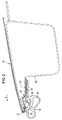
- the convertible top cover denoted by 15 in FIGS. 2 to 4 is screwed to the corresponding profile parts with the aid of molding strips 16, 17 and 18 made of plastic.
- Each molding 16, 17 and 18 is sewn onto the top cover 15 in the area of a seam 19.
- the front edge 20 of the soft top 15 is drawn around the front edge 21 of the cowl frame 11 and, as can be seen, under the cowl profile, overlaps with the front longitudinal edge of the molding strip 16 sewn.
- the molding 16 is both in its longitudinal direction and also in its cross-sectional profile visible in FIG. 2 are adapted to the course of the section of the cowl frame 11 serving here as an attachment for them. The final attachment is done by means of a mounting rail 22 and screws, not shown, the screw axis is designated 23.
- the molding 16 is thus firmly clamped by means of the screw connection between the fastening rail 22 and the cowl bow.
- the front edge of the fastening rail 22 pointing in the direction of travel F is recognizably profiled for pushing in or pushing in a strand-shaped sealing profile 24, which rests sealingly on the upper cross member of the windshield frame when the convertible top is closed.
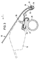
- the molded part 17 on the vehicle's rear clamp 12 (FIG. 3) is also connected to the clamp 12 by means of a fastening rail 25 and screws 26.
- the fastening rail 25 here consists of a sheet metal profile, while the fastening rail 22 shown in FIG. 2 is an extruded profile. But the profile rail 25 also forms an undercut receiving space 27 for an extruded sealing profile 28. In the closed state of the convertible top, this rests on the body section running behind the passenger compartment.
- the molding 18 is screwed to the bracket 13 by means of a fastening rail 29, which indicates the screw axis 30.
- a fastening rail 29 which indicates the screw axis 30.
- the edge edges 31 of the The convertible top fabric 15 is guided about the seam width in front of the edges 32 and 33 of the tension bracket 12 and the holding bracket 13, respectively, and sewed there edge-to-edge with the respective molding 17 and 18, respectively.
- a binding tape 34 (FIG. 3) or 35 (FIG. 4) encloses the seam area. 4, the binding tape 35 also includes a piping tape 36 for forming a rain gutter 37.
Landscapes
- Engineering & Computer Science (AREA)
- Mechanical Engineering (AREA)
- Body Structure For Vehicles (AREA)
- Seal Device For Vehicle (AREA)
- Superstructure Of Vehicle (AREA)
Description
- Die Erfindung bezieht sich auf ein Klapp- bzw. Faltverdeck für Fahrzeuge wie Cabriolets od. dgl. mit einem an Profilen wie Spriegeln, Spannbügeln, Haltewinkein od. dgl. eines tragenden Verdeckgestells unter Vermittlung von Befestigungsprofilen befestigten Verdeckstoff.
- Es ist üblich, den Verdeckstoff an den Stellen der gewünschten festen Verbindung mit den Profilen des Verdeckgestells zu verkleben. Die dazu benötigten lösungsmittelhaltigen Klebstoffe sind jedoch umwelt- und gesundheitsschädigend, weshalb ihre Verwendung problematisch ist. Weiterhin sind die Montagekosten beim Konfektionieren eines Verdeckbezuges beträchtlich, da der Klebstoff zur Aushärtung besondere Behandlung und eine gewisse Zeitspanne benötigt. Zusätzliche Nachteile ergeben sich beim Auswechseln oder Ausbessern eines Verdeckbezuges, denn die Demontage des alten Verdeckbezuges ist umständlich und schwierig. Das Verdeckgestell muß zunächst von den alten Klebstoffresten befreit werden, bevor ein neuer Verdeckbezug mit den eingangs geschilderten Nachteilen auf das Gestell aufgezogen werden kann.
- Der Erfindung liegt folglich die Aufgabe zugrunde, ein Klapp- bzw. Faltverdeck der im Oberbegriff des Patentanspruches 1 genannten Art in geschickter Weise so zu gestalten, daß eine sämtliche bisherigen Nachteile ausschaltende klebstofffreie Verbindung des Verdeckstoffs mit dem Verdeckgestell ermöglicht wird.
- Eine allen Anforderungen entsprechende Lösung dieses Problems besteht entsprechend der Erfindung darin, daß unmittelbar an die Randkanten der an den Verdeckgestell-Profilen zu befestigenden Verdeckstoffpartien Formleisten angenäht sind, die sich im wesentlichen ausschließlich unterhalb der Verdeckgestell-Profile sowie - formlich an diese angepaßt - in deren Längsrichtung erstrecken und daß diese Formleisten mittels jeweils eines Befestigungsprofils an den Verdeckgestell-Profilen angeschraubt sind.
- Bei der Konfektionierung des Verdeckstoffes werden die benötigten Formleisten an die Verdeckstoffkanten angenäht. Danach kann der Verdeckstoff mit den Teilen des Verdeckgestells, an denen er zu befestigen ist, durch lediglich einige Schrauben verbunden werden. Diese Arbeit ist rasch und einfach durchzuführen. Schwierigkeiten beim Auswechseln eines Verdeckstoffes sind ebenso völlig vermieden, da hierzu lediglich der alte Verdeckbezug vom Gestell abgeschraubt und ein neuer angeschraubt wird. Außerdem ist die Zuordnung der Formleisten einerseits zum Verdeckstoff, andererseits zu den Profilen in geschickter Weise so getroffen, daß keine oder keine nennenswerten Verdeckstoffabschnitte mehr über die Profile vorstehen. Dies ist vor allem auch deshalb wichtig, weil der Fahrtwind so keine Angriffsflächen wie sonst an weit überstehenden und deshalb zum Flattern neigenden Verdeckstoffabschnitten finden kann.
- Zum Stand der Technik wird auf das Dokument US-A-4 616 021 (D1) hingewiesen. Dieses Dokument zeigt in Fig. 6 ein mit 62 bezeichnetes "header trim panel", welches im weitesten Sinne als Befestigungsprofil angesehen werden kann und welches zwischen sich und einem mit 22 bezeichneten "front header member" (der vergleichbar ist mit dem Spriegel des Anmeldungsgegenstandes) den freien, unbehandelten Verdeckstoffrand faßt. Eine Formleiste, die entsprechend dem Gegenstand der Anmeldung am Verdeckstoffrand angebracht ist, gibt es hier nicht. Im übrigen lassen sowohl die Fig. 6 des Dokuments US-A-4 616 021 (D1) als auch der zugehörige Text völlig offen, wie die Befestigung des Verdeckstoffrandes tatsächlich hier erfolgt. Auch eine Verklebung ist nicht ausgeschlossen.
- Eine genauere Schilderung einer Verdeckstoff-Befestigung ist unter Bezugnahme auf Fig. 2 in D1 im Bereich des zwei Verdeckstoffpartien 34 und 36 nahtlos miteinander verbindenden Bügels 28 gegeben. Dort werden die einander überlappenden Endbereiche der Verdeckstoff-Partien 34 und 36 zwischen zwei Leisten 42 und 44 eingespannt, wobei die Leiste 42 mittels Schrauben 48 mit der Leiste 44 verbunden wird. Diese Verbindung ist allein offensichtlich so ungenügend und kann bei Belastung, z.B. durch aufblähenden Winddruck, zum Zerreißen der Verdeckstoffränder führen, daß in Sp. 3, Zeilen 54 bis 58 von D1 ausdrücklich erwähnt ist, daß die Konstellation nach Fig. 2 durch zahlreiche Schichten von Klebstoff gesichert sein sollte. Auch der Konstruktion nach Fig. 2 fehlt also gerade die für die Erfindung sehr wesentlichen Merkmale, daß unmittelbar an die Randkanten der an den Profilen zu befestigenden Verdeckstoffpartien Formleisten angenäht sind und daß diese Formleisten mittels Befestigungsprofilen an den Verdeckgestellprofilen angebracht sind.
- Im Zusammenhang mit der Verhinderung des Halterns unter Fahrtwind ist eine Ausgestaltung von Vorteil, die dadurch gekennzeichnet ist, daß der Rand des Verdeckstoffs um die Kante der Profile herumgeführt und unter ihr überlappend mit der Formleiste vernäht ist. Eine solche Anordnung empfiehlt sich vorzugsweise zur Befestigung der gegen den Fahrtwind ausgerichteten Verdeckstoffkanten, also beispielsweise für den am Windlaufspriegel oberhalb des horizontalen Frontscheibenrahmens angebrachten Verdeckstoffrand.
- Eine alternative Randgestaltung, bei der die Randkante des Verdeckstoffes etwa um Nahtbreite vor die Kante der Profile geführt und dort unter Einschluß eines die aufeinanderliegenden Kanten von Verdeckstoff und Formleiste umhüllenden Einfaßbandes mit der Formleiste vernäht ist, wird man für die heckseitige, insbesondere einem Spannbügel zugeordnete Verdeckstoffkante heranziehen, sowie für seitliche Partien, bei denen mittels des Einfaßbandes auch ein eine Regenrinne bildender Keder mit an den Verdeckstoff und die Formleiste angenäht werden kann.
- Die Formleisten bestehen vorzugsweise aus einem biegsamen Kunststoff, insbesondere einem PE-Kunststoff, so daß sie sich dem Verlauf der Profile, an die sie angeschlossen sind, anschmiegen können.
- Schließlich besteht ein weiteres vorteilhaftes Merkmal der Erfindung darin, daß dem Befestigungsprofil - als Schiene ausgebildet - eine rinnen- und/oder leistenförmige Aufnahme zum Ein- oder Überschieben eines strangförmigen Dichtungsprofiles angeformt ist. Auf diese Weise hat ein einstückiges Befestigungsprofil einerseits die Aufgabe, die an die Verdeckstoffkanten angeschlossenen Formleisten zwischen sich und dem zugehörigen Profilteil unter Vermittlung der Befestigungsschrauben einzuspannen sowie andererseits der unmittelbaren Halterung eines Dichtungsprofils zu dienen, welches auf diese Art und Weise auch der Verdeckstoffkante nah benachbart angeordnet werden kann.
- Im übrigen versteht sich die Erfindung am besten aus der nachfolgenden Beschreibung eines in den Zeichnungen dargestellten Ausführungsbeispiels. In den Zeichnungen zeigen:
- Fig. 1
- eine schematische Seitenansicht eines Cabriolet-Verdeckgestells,
- Fig. 2
- einen schematischen Längsschnitt durch die Verdeckstoffbefestigung im Bereich des vorderen Windlaufspriegels (II in Fig. 1) eines Verdeckgestells,
- Fig. 3
- eine der Fig. 2 entsprechende Darstellung im Bereich des hinteren Verdeckgestell-Spannbügels (III in Fig. 1) sowie
- Fig. 4
- eine entsprechende Darstellung im Bereich eines seitlichen Haltewinkels etwa entsprechend der Schnittangabe IV-IV in Fig. 1.
- Fig. 1 zeigt die im Rahmen der Erfindung wesentlichen Teile eines Verdeckgestells 10 für ein Klapp- bzw. Faltverdeck für Cabriolets. In Fahrtrichtung F vorn überspannt ein sogenannter Windlaufspriegel 11 das Verdeckgestell quer zur Fahrtrichtung und liegt bei geschlossenem Verdeck auf dem oberen Querholm des Windschutzscheibenrahmens. An der hinteren Seite des Verdeckgestells 10 befindet sich ein weiteres, etwa U-förmig verlaufendes Profil, der sogenannte Spannbügel 12. An den beiden Fahrzeugseiten erstreckt sich etwa entlang dem hinteren Rand einer Seitenscheibe, ein sogenannter Haltewinkel 13.
- Der über das Verdeckgestell 10 gespannte und von weiteren Spriegeln 14 unterstützte, in Fig. 1 nicht dargestellte Verdeckbezug (15 in den übrigen Figuren), muß mit den erwähnten Profilen, also mit dem Windlaufspriegel 11, dem Spannbügel 12 und den beiden seitlichen Haltewinkeln 13 befestigt werden. Diese Befestigung geschieht bislang dadurch, daß der Verdeckstoff mit seiner Innenfläche an diese Profilteile angeklebt wird.
- Erfindungsgemäß wird der in den Fig. 2 bis 4 mit 15 bezeichnete Verdeckbezug mit Hilfe von Formleisten 16, 17 und 18 aus Kunststoff mit den entsprechenden Profilteilen verschraubt. Dabei ist jede Formleiste 16, 17 und 18 im Bereich einer Naht 19 an den Verdeckbezug 15 angenäht.
- Bei der Befestigung des Verdeckbezugs 15 entsprechend Fig. 2 im Bereich des vorderen Windlaufspriegels 11 ist die vordere Randkante 20 des Verdeckstoffes 15 um die Vorderkante 21 des Windlaufspriegels 11 herumgezogen und unter dem Windlaufspriegel-Profil - wie ersichtlich - überlappend mit der vorderen Längskante der Formleiste 16 vernäht. Die Formleiste 16 ist sowohl in ihrer Längsrichtung als auch in ihrem in Fig. 2 sichtbaren Querschnittsprofil dem Verlauf des hier als Anlage für sie dienenden Abschnitts des Windlaufspriegels 11 angepaßt. Die endgültige Befestigung geschieht mittels einer Befestigungsschiene 22 und nicht dargestellter Schrauben, deren Schraubachse mit 23 bezeichnet ist. Die Formleiste 16 ist also mittels der Schraubverbindung zwischen der Befestigungsschiene 22 und dem Windlaufspriegel fest eingespannt. Die in Fahrtrichtung F weisende Vorderkante der Befestigungsschiene 22 ist erkennbar profiliert zum Auf- bzw. Einschieben eines strangförmigen Dichtungsprofiles 24, das bei geschlossenem Verdeck dichtend auf dem oberen Querholm des Windschutzscheibenrahmens aufliegt.
- Das Formteil 17 am fahrzeughinteren Spannbügel 12 (Fig. 3) wird ebenfalls mit Hilfe einer Befestigungsschiene 25 und Schrauben 26 mit dem Spannbügel 12 verbunden. Die Befestigungsschiene 25 besteht hier aus einem Blechprofil, während es sich bei der in Fig. 2 dargestellten Befestigungsschiene 22 um ein Strangpreßprofil handelt. Aber auch die Profilschiene 25 bildet einen hinterschnittenen Aufnahmeraum 27 für ein strangförmiges Dichtungsprofil 28 aus. Dieses liegt im geschlossenen Zustand des Verdecks auf dem hinter dem Fahrgastraum umlaufenden Karosserieabschnitt auf.
- An den beiden Fahrzeugseiten schließlich ist die Formleiste 18 mittels einer Befestigungsschiene 29 mit dem Haltewinkel 13 verschraubt, was die Schraubachse 30 andeutet. Sowohl hier als auch im Bereich des Spannbügels 12 entsprechend Fig. 3 sind die Randkanten 31 des Verdeckstoffs 15 etwa um Nahtbreite vor die Kanten 32 bzw. 33 des Spannbügels 12 bzw. des Haltewinkels 13 geführt und dort Kante-an-Kante mit der jeweiligen Formleiste 17 bzw. 18 vernäht. Ein Einfaßband 34 (Fig. 3) bzw. 35 (Fig. 4) umschließt den Nahtbereich. Bei der seitlichen Verdeckbefestigung an den Haltewinkeln 13 entsprechend Fig. 4 schließt das Einfaßband 35 im übrigen noch ein Kederband 36 zur Ausbildung einer Regenrinne 37 ein.
Claims (6)
- Klapp- bzw. Faltverdeck für Fahrzeuge wie Cabriolets od. dgl. mit einem an Profilen wie Spriegeln, Spannbügeln, Haltewinkeln od. dgl. eines tragenden Verdeckgestells unter Vermittlung von Befestigungsprofilen befestigten Verdeckstoff, dadurch gekennzeichnet, daß unmittelbar an die Randkanten (20, 31) der an den Verdeckgesell-Profilen zu befestigenden Verdeckstoffpartien Formleisten (16, 17, 18) angenäht sind, die sich im wesentlichen ausschließlich unterhalb der Verdeckgestell-Profile (11, 12, 13) sowie - formlich an diese angepaßt - in deren Längsrichtung erstrecken, und daß diese Formleisten (16, 17, 18) mittels jeweils eines Befestigungsprofils (22, 25, 29) an den Verdeckgestell-Profilen (11, 12, 13) angeschraubt sind.
- Verdeck nach Anspruch 1, dadurch gekennzeichnet, daß die Formleiste (16) sowohl in ihrer Längsrichtung als auch in ihrem Querschnittsprofil dem Verlauf des als Anlage für sie dienenden Abschnitts des Windlaufspriegels (11) angepaßt ist.
- Verdeck nach Anspruch 1, dadurch gekennzeichnet, daß die Randkante (20) des Verdeckstoffs (15) um die Kante (21) der Profile (11) herumgeführt und unter ihr überlappend mit der Formleiste (16) vernäht ist.
- Verdeck nach Anspruch 1, dadurch gekennzeichnet, daß die Randkante (31) des Verdeckstoffs (15) etwa um Nahtbreite vor die Kante (31; 32) des Profils (12; 13) geführt und dort unter Einschluß eines die aufeinanderliegenden Kanten von Verdeckstoff (15) und Formleiste (17; 18) umhüllenden Einfaßbandes (34; 35) mit der Formleiste (17; 18) vernäht ist.
- Verdeck nach Anspruch 1 oder einem der folgenden, dadurch gekennzeichnet, daß die Formleisten (16; 17; 18) aus biegsamem Kunststoff, insbesondere einem PE-Kunststoff, bestehen.
- Verdeck nach Anspruch 1 oder einem der folgenden, dadurch gekennzeichnet, daß dem Befestigungsprofil (22, 25, 29) - als Schiene ausgebildet - eine rinnen- und/oder leistenförmige Aufnahme (27) zum Ein- und/oder Überschieben eines strangförmigen Dichtungsprofils (24, 28) angeformt ist.
Applications Claiming Priority (2)
| Application Number | Priority Date | Filing Date | Title |
|---|---|---|---|
| DE4112256 | 1991-04-15 | ||
| DE4112256A DE4112256C3 (de) | 1991-04-15 | 1991-04-15 | Klapp- bzw. Faltverdeck für Fahrzeuge wie Cabriolets o. dgl. |
Publications (2)
| Publication Number | Publication Date |
|---|---|
| EP0509326A1 EP0509326A1 (de) | 1992-10-21 |
| EP0509326B1 true EP0509326B1 (de) | 1997-07-02 |
Family
ID=6429616
Family Applications (1)
| Application Number | Title | Priority Date | Filing Date |
|---|---|---|---|
| EP92105675A Expired - Lifetime EP0509326B1 (de) | 1991-04-15 | 1992-04-02 | Klapp- bzw. Faltverdeck für Fahrzeuge wie Cabriolets od.dgl. |
Country Status (4)
| Country | Link |
|---|---|
| US (1) | US5269582A (de) |
| EP (1) | EP0509326B1 (de) |
| DE (2) | DE4112256C3 (de) |
| ES (1) | ES2106102T3 (de) |
Cited By (1)
| Publication number | Priority date | Publication date | Assignee | Title |
|---|---|---|---|---|
| EP0997334A2 (de) | 1998-10-28 | 2000-05-03 | Wilhelm Karmann GmbH | Kraftfahrzeug mit einem faltbaren Verdeck |
Families Citing this family (22)
| Publication number | Priority date | Publication date | Assignee | Title |
|---|---|---|---|---|
| DE4234811C2 (de) * | 1992-10-15 | 1995-09-21 | Bayerische Motoren Werke Ag | Cabriolet-Verdeck |
| DE4319484C1 (de) * | 1993-06-11 | 1994-07-07 | Porsche Ag | Einrichtung zur Befestigung eines unteren Randbereiches eines Verdeckbezuges |
| DE4441671C1 (de) * | 1994-11-23 | 1995-11-16 | Porsche Ag | Faltverdeck für Fahrzeuge, insbesondere Personenkraftwagen |
| DE4441670C1 (de) * | 1994-11-23 | 1995-11-16 | Porsche Ag | Faltverdeck für Kraftfahrzeuge |
| DE4441669C1 (de) * | 1994-11-23 | 1995-11-16 | Porsche Ag | Faltverdeck für Fahrzeuge |
| DE4441667C1 (de) * | 1994-11-23 | 1995-12-14 | Porsche Ag | Befestigung eines Verdeckbezugs an einem Klapp- bzw. Faltverdeck für Fahrzeuge wie Cabriolets oder dgl. |
| DE9419035U1 (de) * | 1994-11-26 | 1995-03-09 | Wilhelm Karmann GmbH, 49084 Osnabrück | Cabriolet-Fahrzeug |
| US5848819A (en) * | 1996-04-23 | 1998-12-15 | Dura Convertible Systems, Inc. | Convertible topstack with extruded & ajustable side rails |
| DE29718206U1 (de) * | 1997-10-14 | 1998-03-19 | Wilhelm Karmann GmbH, 49084 Osnabrück | Cabriolet-Fahrzeug |
| US6832805B2 (en) * | 2002-10-02 | 2004-12-21 | Wilhelm Karmann Gmbh | Convertible top system for vehicle |
| US7144063B2 (en) * | 2003-05-02 | 2006-12-05 | Asc Incorporated | Convertible roof fabric attachment |
| DE102007059077A1 (de) | 2007-12-07 | 2009-06-10 | Wilhelm Karmann Gmbh | Verdeck eines Cabriolet-Fahrzeugs |
| DE102008013894A1 (de) | 2008-03-12 | 2009-09-17 | Wilhelm Karmann Gmbh | Leiste zum Anbringen von Verdeckstoff an einen Verdeckspannbügel und Verdeck mit einer Leiste |
| DE102009013278A1 (de) | 2009-03-14 | 2010-09-16 | Magna Car Top Systems Gmbh | Bewegliches Dach für ein Kraftfahrzeug |
| DE102010010944A1 (de) | 2010-03-11 | 2011-09-15 | Magna Car Top Systems Gmbh | Dachkappe für ein Faltverdeck |
| FR2978381B1 (fr) | 2011-07-28 | 2013-08-30 | Webasto Systemes Carrosserie | Toile de toit ouvrant et toit ouvrant |
| DE102012013687A1 (de) * | 2012-07-07 | 2014-05-08 | Volkswagen Aktiengesellschaft | Faltdach für einen Personenkraftwagen |
| DE102013213429B3 (de) | 2013-07-09 | 2014-10-09 | Magna Car Top Systems Gmbh | Bewegliches Dach für ein Kraftfahrzeug |
| JP6242639B2 (ja) * | 2013-09-19 | 2017-12-06 | 西川ゴム工業株式会社 | ウェザストリップ |
| DE102014110646A1 (de) | 2014-07-29 | 2016-02-04 | Dr. Ing. H.C. F. Porsche Aktiengesellschaft | Fahrzeugverdeck |
| DE102020208589B4 (de) | 2020-07-08 | 2022-10-06 | Magna Car Top Systems Gmbh | Faltverdeck für ein Cabriolet-Fahrzeug |
| DE102021213223B4 (de) | 2021-11-24 | 2023-06-07 | Magna Car Top Systems Gmbh | Verfahren zur Herstellung eines Verdeckbezugs eines Faltverdecks für ein Cabriolet-Fahrzeug sowie Faltverdeck für ein Cabriolet-Fahrzeug |
Family Cites Families (11)
| Publication number | Priority date | Publication date | Assignee | Title |
|---|---|---|---|---|
| FR674015A (de) * | 1930-02-24 | |||
| DE519499C (de) * | 1931-02-28 | Anton Aumueller | Verdeck, insbesondere fuer Kraftfahrzeuge, mit Spriegeln, deren Enden mit den durch Einlagen verstaerkten Dachstoffraendern durch eine gemeinsame Schraub-vorrichtung an Laengsschienen der Wagenkastenseitenwaende festgespannt werden | |
| US1778356A (en) * | 1929-03-30 | 1930-10-14 | Locke & Company | Automobile body |
| DE599270C (de) * | 1931-08-09 | 1934-06-28 | Wilhelm Vorwerk | Klemmverschluss fuer Stoffbahnen |
| FR870098A (fr) * | 1939-02-13 | 1942-03-02 | Daimler Benz Ag | Dispositif pour la fixation du bord avant du tissu de capotes à soufflet pour voitures automobiles |
| US2544580A (en) * | 1949-02-04 | 1951-03-06 | Ovila J Blanchet | Rain-drain attachment for automobile tops |
| US2714525A (en) * | 1953-03-19 | 1955-08-02 | Kessler Milton | Flexible drip molding |
| US2785003A (en) * | 1954-11-15 | 1957-03-12 | Louis J Zaravsey | Hold-down clip devices for vehicle convertible top covers |
| US3486788A (en) * | 1967-10-23 | 1969-12-30 | Kayline Mfg Inc | Demountable top fastener device |
| US4626021A (en) * | 1985-04-08 | 1986-12-02 | Muscat Peter P | Convertible top cover |
| DE8816696U1 (de) * | 1988-12-06 | 1990-05-03 | Mehler Vario System GmbH, 6400 Fulda | Lösbare Fensterbefestigung in einem flexiblen Klappverdeck eines Fahrzeuges |
-
1991
- 1991-04-15 DE DE4112256A patent/DE4112256C3/de not_active Expired - Fee Related
-
1992
- 1992-04-02 EP EP92105675A patent/EP0509326B1/de not_active Expired - Lifetime
- 1992-04-02 DE DE59208653T patent/DE59208653D1/de not_active Expired - Fee Related
- 1992-04-02 ES ES92105675T patent/ES2106102T3/es not_active Expired - Lifetime
- 1992-04-14 US US07/868,367 patent/US5269582A/en not_active Expired - Lifetime
Cited By (1)
| Publication number | Priority date | Publication date | Assignee | Title |
|---|---|---|---|---|
| EP0997334A2 (de) | 1998-10-28 | 2000-05-03 | Wilhelm Karmann GmbH | Kraftfahrzeug mit einem faltbaren Verdeck |
Also Published As
| Publication number | Publication date |
|---|---|
| EP0509326A1 (de) | 1992-10-21 |
| DE4112256A1 (de) | 1992-10-22 |
| DE59208653D1 (de) | 1997-08-07 |
| ES2106102T3 (es) | 1997-11-01 |
| DE4112256C3 (de) | 1998-06-18 |
| DE4112256C2 (de) | 1993-10-14 |
| US5269582A (en) | 1993-12-14 |
Similar Documents
| Publication | Publication Date | Title |
|---|---|---|
| DE4112256C2 (de) | Klapp- bzw. Faltverdeck für Fahrzeuge wie Cabriolets o. dgl. | |
| EP0622258B1 (de) | Heckfensterscheibe für Cabriolet-Fahrzeuge | |
| DE3027366A1 (de) | Dichtungsstrang fuer karosserien, insbesondere kraftfahrzeugkarosserien | |
| EP1900561A2 (de) | Verdeck für ein Cabriolet | |
| DE3241906A1 (de) | Fahrzeugkarosserie mit zumindest einer daran durch ein haftmittel befestigten zier- oder schutzleiste | |
| DE4001136C2 (de) | ||
| EP1092575A2 (de) | Klapp-bzw. Faltverdeck für Fahrzeuge wie Cabriolets od. dgl. | |
| EP0836960A1 (de) | Cabriolet-Fahrzeug | |
| EP1059184A2 (de) | Anordnung zur Befestigung eines Randbereiches einer Fahrzeuginnenverkleidung an einem flexiblen Verdeck | |
| DE102013112963A1 (de) | Verdeck für ein Cabriolet | |
| EP0805057B1 (de) | Klapp- bzw. Faltverdeck für Fahrzeuge wie Cabriolets od.dgl. | |
| DE102006036658B3 (de) | Spannbügel für ein Fahrzeugdach, vorzugsweise für Kraftfahrzeuge | |
| DE4412283C1 (de) | Windschutzrahmen für ein offenes Kraftfahrzeug | |
| EP0997334A2 (de) | Kraftfahrzeug mit einem faltbaren Verdeck | |
| DE102008051705B4 (de) | Bewegliches Dach für einen Personenkraftwagen | |
| EP2468545B2 (de) | Faltverdeck für ein Fahrzeug mit einem Spannbügel | |
| DE4314717C2 (de) | Fahrzeugdach mit einem zumindestens teilweise aus flexiblem Verdeckstoff bestehenden Verdeck | |
| DE102009018587A1 (de) | Dachkappe eines zusammenlegbaren Faltverdecks | |
| DE2206556C3 (de) | Obere Lagerung der feststehenden Seitenteile, wie rahmenlose Seitenscheiben oder Seitenwände, für Aufbauten von Schleppern, fahrbaren Baumaschinen u.dgl. Fahrzeugen | |
| DE102008060686B4 (de) | Dichtung zwischen Fahrzeugaußenhautelementen | |
| DE102016200203B4 (de) | Faltverdeck mit optimiertem Dachrahmen | |
| DE29918232U1 (de) | Klapp- bzw. Faltverdeck für Fahrzeuge wie Cabriolets o.dgl. | |
| DE1630951A1 (de) | Verdeck fuer Fahrzeuge | |
| DE2154251C3 (de) | Obere Lagerung der feststehenden Seitenteile, wie rahmenlose Seitenscheiben oder Seitenwände, für Aufbauten von Schleppern, fahrbaren Baumaschinen u.dgl. Fahrzeugen | |
| AT270411B (de) | Winterverdeck für Kabrioletts |
Legal Events
| Date | Code | Title | Description |
|---|---|---|---|
| PUAI | Public reference made under article 153(3) epc to a published international application that has entered the european phase |
Free format text: ORIGINAL CODE: 0009012 |
|
| AK | Designated contracting states |
Kind code of ref document: A1 Designated state(s): DE ES FR GB IT SE |
|
| 17P | Request for examination filed |
Effective date: 19930222 |
|
| 17Q | First examination report despatched |
Effective date: 19940906 |
|
| GRAG | Despatch of communication of intention to grant |
Free format text: ORIGINAL CODE: EPIDOS AGRA |
|
| GRAH | Despatch of communication of intention to grant a patent |
Free format text: ORIGINAL CODE: EPIDOS IGRA |
|
| GRAH | Despatch of communication of intention to grant a patent |
Free format text: ORIGINAL CODE: EPIDOS IGRA |
|
| ITF | It: translation for a ep patent filed | ||
| GRAA | (expected) grant |
Free format text: ORIGINAL CODE: 0009210 |
|
| AK | Designated contracting states |
Kind code of ref document: B1 Designated state(s): DE ES FR GB IT SE |
|
| GBT | Gb: translation of ep patent filed (gb section 77(6)(a)/1977) |
Effective date: 19970704 |
|
| REF | Corresponds to: |
Ref document number: 59208653 Country of ref document: DE Date of ref document: 19970807 |
|
| ET | Fr: translation filed | ||
| REG | Reference to a national code |
Ref country code: ES Ref legal event code: FG2A Ref document number: 2106102 Country of ref document: ES Kind code of ref document: T3 |
|
| PLBE | No opposition filed within time limit |
Free format text: ORIGINAL CODE: 0009261 |
|
| STAA | Information on the status of an ep patent application or granted ep patent |
Free format text: STATUS: NO OPPOSITION FILED WITHIN TIME LIMIT |
|
| 26N | No opposition filed | ||
| REG | Reference to a national code |
Ref country code: GB Ref legal event code: IF02 |
|
| PGFP | Annual fee paid to national office [announced via postgrant information from national office to epo] |
Ref country code: ES Payment date: 20030429 Year of fee payment: 12 |
|
| PG25 | Lapsed in a contracting state [announced via postgrant information from national office to epo] |
Ref country code: ES Free format text: LAPSE BECAUSE OF NON-PAYMENT OF DUE FEES Effective date: 20040403 |
|
| REG | Reference to a national code |
Ref country code: ES Ref legal event code: FD2A Effective date: 20040403 |
|
| PGFP | Annual fee paid to national office [announced via postgrant information from national office to epo] |
Ref country code: SE Payment date: 20060411 Year of fee payment: 15 Ref country code: GB Payment date: 20060411 Year of fee payment: 15 |
|
| PGFP | Annual fee paid to national office [announced via postgrant information from national office to epo] |
Ref country code: FR Payment date: 20060420 Year of fee payment: 15 |
|
| PGFP | Annual fee paid to national office [announced via postgrant information from national office to epo] |
Ref country code: IT Payment date: 20060430 Year of fee payment: 15 |
|
| PGFP | Annual fee paid to national office [announced via postgrant information from national office to epo] |
Ref country code: DE Payment date: 20060518 Year of fee payment: 15 |
|
| GBPC | Gb: european patent ceased through non-payment of renewal fee |
Effective date: 20070402 |
|
| PG25 | Lapsed in a contracting state [announced via postgrant information from national office to epo] |
Ref country code: DE Free format text: LAPSE BECAUSE OF NON-PAYMENT OF DUE FEES Effective date: 20071101 |
|
| PG25 | Lapsed in a contracting state [announced via postgrant information from national office to epo] |
Ref country code: GB Free format text: LAPSE BECAUSE OF NON-PAYMENT OF DUE FEES Effective date: 20070402 |
|
| PG25 | Lapsed in a contracting state [announced via postgrant information from national office to epo] |
Ref country code: SE Free format text: LAPSE BECAUSE OF NON-PAYMENT OF DUE FEES Effective date: 20070403 |
|
| PG25 | Lapsed in a contracting state [announced via postgrant information from national office to epo] |
Ref country code: FR Free format text: LAPSE BECAUSE OF NON-PAYMENT OF DUE FEES Effective date: 20070430 |
|
| PG25 | Lapsed in a contracting state [announced via postgrant information from national office to epo] |
Ref country code: IT Free format text: LAPSE BECAUSE OF NON-PAYMENT OF DUE FEES Effective date: 20070402 |