EP0509218B1 - Zahnradpumpe - Google Patents
Zahnradpumpe Download PDFInfo
- Publication number
- EP0509218B1 EP0509218B1 EP92103274A EP92103274A EP0509218B1 EP 0509218 B1 EP0509218 B1 EP 0509218B1 EP 92103274 A EP92103274 A EP 92103274A EP 92103274 A EP92103274 A EP 92103274A EP 0509218 B1 EP0509218 B1 EP 0509218B1
- Authority
- EP
- European Patent Office
- Prior art keywords
- gear
- housing
- conveying
- conveyed
- lubricant
- Prior art date
- Legal status (The legal status is an assumption and is not a legal conclusion. Google has not performed a legal analysis and makes no representation as to the accuracy of the status listed.)
- Expired - Lifetime
Links
- 239000000314 lubricant Substances 0.000 claims description 15
- 239000000126 substance Substances 0.000 claims 3
- 238000000926 separation method Methods 0.000 claims 1
- 239000000463 material Substances 0.000 description 10
- 238000007789 sealing Methods 0.000 description 7
- 239000000203 mixture Substances 0.000 description 3
- 239000007921 spray Substances 0.000 description 2
- VOPWNXZWBYDODV-UHFFFAOYSA-N Chlorodifluoromethane Chemical compound FC(F)Cl VOPWNXZWBYDODV-UHFFFAOYSA-N 0.000 description 1
- 239000004698 Polyethylene Substances 0.000 description 1
- 150000001875 compounds Chemical class 0.000 description 1
- 230000006835 compression Effects 0.000 description 1
- 238000007906 compression Methods 0.000 description 1
- 230000000694 effects Effects 0.000 description 1
- 239000013013 elastic material Substances 0.000 description 1
- 239000007788 liquid Substances 0.000 description 1
- 230000007257 malfunction Effects 0.000 description 1
- 230000000149 penetrating effect Effects 0.000 description 1
- -1 polyethylene Polymers 0.000 description 1
- 229920000573 polyethylene Polymers 0.000 description 1
- 239000012260 resinous material Substances 0.000 description 1
- 229920001169 thermoplastic Polymers 0.000 description 1
- 239000004416 thermosoftening plastic Substances 0.000 description 1
Images
Classifications
-
- F—MECHANICAL ENGINEERING; LIGHTING; HEATING; WEAPONS; BLASTING
- F04—POSITIVE - DISPLACEMENT MACHINES FOR LIQUIDS; PUMPS FOR LIQUIDS OR ELASTIC FLUIDS
- F04C—ROTARY-PISTON, OR OSCILLATING-PISTON, POSITIVE-DISPLACEMENT MACHINES FOR LIQUIDS; ROTARY-PISTON, OR OSCILLATING-PISTON, POSITIVE-DISPLACEMENT PUMPS
- F04C13/00—Adaptations of machines or pumps for special use, e.g. for extremely high pressures
- F04C13/001—Pumps for particular liquids
- F04C13/002—Pumps for particular liquids for homogeneous viscous liquids
-
- B—PERFORMING OPERATIONS; TRANSPORTING
- B29—WORKING OF PLASTICS; WORKING OF SUBSTANCES IN A PLASTIC STATE IN GENERAL
- B29C—SHAPING OR JOINING OF PLASTICS; SHAPING OF MATERIAL IN A PLASTIC STATE, NOT OTHERWISE PROVIDED FOR; AFTER-TREATMENT OF THE SHAPED PRODUCTS, e.g. REPAIRING
- B29C48/00—Extrusion moulding, i.e. expressing the moulding material through a die or nozzle which imparts the desired form; Apparatus therefor
- B29C48/25—Component parts, details or accessories; Auxiliary operations
- B29C48/36—Means for plasticising or homogenising the moulding material or forcing it through the nozzle or die
- B29C48/365—Means for plasticising or homogenising the moulding material or forcing it through the nozzle or die using pumps, e.g. piston pumps
- B29C48/37—Gear pumps
-
- B—PERFORMING OPERATIONS; TRANSPORTING
- B29—WORKING OF PLASTICS; WORKING OF SUBSTANCES IN A PLASTIC STATE IN GENERAL
- B29C—SHAPING OR JOINING OF PLASTICS; SHAPING OF MATERIAL IN A PLASTIC STATE, NOT OTHERWISE PROVIDED FOR; AFTER-TREATMENT OF THE SHAPED PRODUCTS, e.g. REPAIRING
- B29C48/00—Extrusion moulding, i.e. expressing the moulding material through a die or nozzle which imparts the desired form; Apparatus therefor
- B29C48/25—Component parts, details or accessories; Auxiliary operations
- B29C48/36—Means for plasticising or homogenising the moulding material or forcing it through the nozzle or die
- B29C48/375—Plasticisers, homogenisers or feeders comprising two or more stages
- B29C48/387—Plasticisers, homogenisers or feeders comprising two or more stages using a screw extruder and a gear pump
-
- B—PERFORMING OPERATIONS; TRANSPORTING
- B29—WORKING OF PLASTICS; WORKING OF SUBSTANCES IN A PLASTIC STATE IN GENERAL
- B29C—SHAPING OR JOINING OF PLASTICS; SHAPING OF MATERIAL IN A PLASTIC STATE, NOT OTHERWISE PROVIDED FOR; AFTER-TREATMENT OF THE SHAPED PRODUCTS, e.g. REPAIRING
- B29C48/00—Extrusion moulding, i.e. expressing the moulding material through a die or nozzle which imparts the desired form; Apparatus therefor
- B29C48/25—Component parts, details or accessories; Auxiliary operations
- B29C48/36—Means for plasticising or homogenising the moulding material or forcing it through the nozzle or die
- B29C48/395—Means for plasticising or homogenising the moulding material or forcing it through the nozzle or die using screws surrounded by a cooperating barrel, e.g. single screw extruders
-
- F—MECHANICAL ENGINEERING; LIGHTING; HEATING; WEAPONS; BLASTING
- F04—POSITIVE - DISPLACEMENT MACHINES FOR LIQUIDS; PUMPS FOR LIQUIDS OR ELASTIC FLUIDS
- F04C—ROTARY-PISTON, OR OSCILLATING-PISTON, POSITIVE-DISPLACEMENT MACHINES FOR LIQUIDS; ROTARY-PISTON, OR OSCILLATING-PISTON, POSITIVE-DISPLACEMENT PUMPS
- F04C15/00—Component parts, details or accessories of machines, pumps or pumping installations, not provided for in groups F04C2/00 - F04C14/00
- F04C15/0003—Sealing arrangements in rotary-piston machines or pumps
- F04C15/0023—Axial sealings for working fluid
- F04C15/0026—Elements specially adapted for sealing of the lateral faces of intermeshing-engagement type machines or pumps, e.g. gear machines or pumps
-
- B—PERFORMING OPERATIONS; TRANSPORTING
- B29—WORKING OF PLASTICS; WORKING OF SUBSTANCES IN A PLASTIC STATE IN GENERAL
- B29C—SHAPING OR JOINING OF PLASTICS; SHAPING OF MATERIAL IN A PLASTIC STATE, NOT OTHERWISE PROVIDED FOR; AFTER-TREATMENT OF THE SHAPED PRODUCTS, e.g. REPAIRING
- B29C48/00—Extrusion moulding, i.e. expressing the moulding material through a die or nozzle which imparts the desired form; Apparatus therefor
- B29C48/03—Extrusion moulding, i.e. expressing the moulding material through a die or nozzle which imparts the desired form; Apparatus therefor characterised by the shape of the extruded material at extrusion
Definitions
- the invention relates to a gear pump, consisting of a housing provided with an inlet and an outlet channel and two externally toothed gear wheels, the bearings of which are sealed in the housing against the conveyed material.
- Such a gear pump is known from DE 90 11 156.7 U1.
- This known gear pump is used to pump highly viscous, resinous liquids. With these, it is necessary that material to be conveyed does not penetrate into the bearings of the gear wheels. Because this would lead to malfunctions in the operation of the gear pump, the resinous material to be conveyed would solidify in the bearings, thereby forming an increased bearing resistance, thereby generating strong frictional heat, which would lead to charring of the material to be conveyed into the bearings, which would wear the bearings and settle down.
- axle seals and an axially acting return thread are provided, for which purpose the gear has a central recess into which the bearing housing projects, which carries the return thread on the outside and seals on its inside.
- the gears are mounted on one side here, because with this type of storage the number of sealing and return measures is only half that of double-sided ones Storage measures required.
- this one-sided mounting has the disadvantage that under the high pressure occurring in the toothing area, the gear carrying the gear at its end, which rests in the bearings, bends elastically and therefore the gear wedges in the housing, which in turn makes it necessary for the
- the gap between the end face of the gear and the housing wall must be dimensioned sufficiently large to accommodate such a canted gear. This in turn leads to greater leakage flow and thus more mixture residues in the housing.
- a gear pump in which the problem of canting does not occur, is known from US-A-31 33 506, in which the gear wheels have a central cavity in which a bearing-bearing pin engages.
- the present application avoids the disadvantages of the prior art. It is the object of the present application to reduce wear with simple means and to design the gear pump in such a way that it promotes rubber compound types that are difficult to convey without loss of service life.
- the invention consists in the fact that the seals are arranged in the form of a conveyor spiral for the return conveying of conveyed material on the end faces of the gearwheels for separating the conveying space and the bearing of the gearwheels, that delivery threads for the return of lubricants are arranged on the wave-shaped or hollow-pin-shaped parts of the gearwheels that high pressures act on the lubricant, and that channels at the point where the delivery thread and delivery spiral meet are provided through which the leakage flow of the conveyed material and the lubricant is discharged to the outside.
- the leakage flow of both the conveyed material and the lubricant is kept low.
- the delivery spiral and the delivery thread can neither completely return the material to be conveyed nor the lubricant, nor do they need it. It is advantageous both for keeping the lubricant clean and for keeping the conveyed good clean when the part of the leakage flow penetrating through the return means conveying spiral and conveying thread is discharged to the outside.
- the ducts are used for discharge at the point where the feed thread and the feed spiral meet.
- the gear pump is flanged with its housing 1 to the cylinder 2 of the extruder, which receives a bushing 3 in which the extruder screw 4 rotates to convey and plasticize the rubber mixture.
- two gear wheels 5, 6 rotate and convey the extrudate from the input channel 7 into the outlet channel 8 and from there into the spray head 9, which is flanged to the housing 1.
- a recess 10 is machined into the walls of the outlet channel 8 parallel to the end faces of the gear wheels 5, 6 in order to be able to convey conveyed material under high pressure into the outlet channel between the teeth of the gear wheels 5, 6.
- conveyor spirals 11 are arranged on the end faces of the gear wheels 5, 6 and conveyor threads 12 are arranged on the wave-shaped or hollow-pin-shaped parts.
- These conveying spirals 11 and conveying threads 12 are used for the return conveying, namely the conveying spirals 11 for the return of leaked goods to be conveyed and the conveying thread 12 for the return of lubricant.
- these work equipment can neither completely return the material to be conveyed nor the lubricant, nor should they.
- Channels 13 are used for this purpose, which can expediently also be connected to a groove arranged in the housing.
- the effect of the sealing spirals and sealing threads can be decisive by pressing in components that are compatible with the mixture, for example certain thermoplastics, preferably polyethylene, for example with a metering pump in the area of the sealing spirals or threads can be improved. In some cases, the leak outlets can then be dispensed with.
- the smaller gear 6 is mounted on a bolt 14 which has several sections of different diameters. Between the central section of this bolt 14 and the inner walls of the gear 6, needles 15 of a needle bearing are arranged in four parallel rows. At one end, this bolt 14 has a flange 16 which is fastened in the housing 1 by means of screws 17. At its other end, the bolt 14 carries a thread onto which a nut 18 is screwed, which engages in a recess in the housing 1.
- the gear wheel 5 of larger diameter is connected to the drive shaft 19 or it is made in one piece with this drive shaft.
- This shaft 19 is provided in the area below the teeth 20 with a cavity 21 in which a bearing pin 22 engages.
- This bearing pin 22 is of stepped design, with its central part it sits in a snug fit in the housing 1, one end is designed as a flange 23 and fastened in the housing 1 by means of screws 17.
- the end part of this bearing journal 22 protruding into the interior of the housing 1 carries the inner ring or rings for needle bearings 24, which support the gear wheel 5, which is thus mounted directly under the teeth and which, on the one hand, is supported by the needle bearings 24, on the other hand, is supported by needle bearings 25 for supporting the shaft 19.
- the housing itself is made up of three parts 26, 27, 28, which are clamped together by screws 29.
- a strainer screen 30 is arranged in the inlet channel 7, which serves to keep foreign objects away from the gear wheels 5, 6.
- a screen changing device is provided, namely a slide 32 which can be displaced by means of the servo motor 31 and which receives two strainer screens 30 which can be inserted alternately into the extrudate stream, one screen being located outside the extrudate stream and here can be cleaned or replaced outside the device.
Landscapes
- Engineering & Computer Science (AREA)
- Mechanical Engineering (AREA)
- General Engineering & Computer Science (AREA)
- Rotary Pumps (AREA)
Description
- Die Erfindung betrifft eine Zahnradpumpe, bestehend aus einem mit einem Einlaß- und einem Auslaßkanal versehenen Gehäuse und zwei außenverzahnten Zahnrädern, deren Lager abgedichtet gegen das Fördergut im Gehäuse gelagert sind.
- Eine derartige Zahnradpumpe ist aus der DE 90 11 156.7 U1 bekannt geworden. Diese bekannte Zahnradpumpe dient zur Förderung von hochviskosen, verharzenden Flüssigkeiten. Bei diesen ist es notwendig, daß Fördergut nicht in die Lager der Zahnräder eindringt. Denn das würde zu Störungen des Betriebes der Zahnradpumpe führen, das verharzende Fördergut würde in den Lagern sich verfestigen, dabei einen erhöhten Lagerwiderstand bilden, dabei starke Reibungswärme erzeugen, die zu einer Verkohlung des in die Lager eingedrungenen Fördergutes führen würde, wodurch die Lager verschleißen und sich festsetzen. Daher sind bei der Zahnradpumpe des DE 90 11 156 U1 Achsdichtungen und ein axial wirkendes Rückfördergewinde vorgesehen, wozu das Zahnrad eine zentrale Ausnehmung erhalten hat, in welche das Lagergehäuse hineinragt, welches auf seiner Außenseite das Rückfördergewinde und auf seiner Innenseite Dichtungen trägt. Die Zahnräder sind hier einseitig gelagert, weil bei dieser Lagerungsart die Anzahl der Dichtungs- und Rückfördermaßnahmen nur die Hälfte der bei doppelseitiger Lagerung notwendigen Maßnahmen beträgt. Diese einseitige Lagerung hat jedoch den Nachteil, daß unter den hohen, im Verzahnungsbereich auftretenden Drucken sich die das Zahnrad an ihrem Ende tragende, in den Lagern ruhende Welle elastisch durchbiegt und daher sich das Zahnrad im Gehäuse verkantet, was es wiederum notwendig macht, daß der Spalt zwischen Stirnseite des Zahnrades und Gehäusewandung ausreichend groß dimensioniert werden muß, um ein derartig verkantetes Zahnrad aufzunehmen. Das wiederum führt zu größerer Leckströmung und damit zu mehr Mischungsresten im Gehäuse.
- Eine Zahnradpumpe, bei der das Problem der Verkantung nicht auftritt, ist aus der US-A-31 33 506 bekannt geworden, bei der die Zahnräder einen zentralen Hohlraum aufweisen, in welchen ein Wälzlager tragender Zapfen eingreift.
- Damit ist das Abdichtungsproblem jedoch noch nicht gelöst. Ebenso wie bei Zahnradpumpen treten bei Schraubenverdichtern und Flügelzellenverdichtern, die ebenfalls mit rotierenden Verdichtungselementen arbeiten, Abdichtungsprobleme an den rotierenden Elementen auf. Bei der DE 36 09 996 A1 versucht man diese durch stirnseitig an den rotierenden Elementen anliegende Scheiben aus elastischem Material mit eingeformten radialen und Umfangsnuten zu lösen, Mittel die bei den hohen in Zahnradpumpen auftretenden Drucken kaum einsetzbar sind. Bei der DE 29 38 276 A1 sind in die Stirnseiten der Rotoren eine Vielzahl von schaufelförmigen Nuten eingearbeitet, die jede für sich nach ihrer Kurvenform einen Teil einer Spirale bilden und die eine Leckströmung des in dieser Maschine verdichteten Frigen-Gases vermindern, weil sie nach Art von gegensinnig arbeitenden Schaufeln den Eintritt in den Spalt zwischen Stirnseite und Gehäuse hindern, jedoch nicht unterbinden. In die Wellenzapfen der Rotoren sind anstelle von mechanischen Lagern Gewinde eines Gaslagers eingearbeitet, welche das verdichtete Gas über die Länge der Wellenzapfen verteilen.
- Bei Zahnradpumpen treten insbesondere im Bereich der ineinandergreifenden Zähne extrem hohe Drucke auf, bei denen auch an den Stirnseiten der Zahnräder angebrachte schaufelartige Nuten kaum wirksam sind.
- Die vorliegende Anmeldung vermeidet die Nachteile des Standes der Technik. Es ist die Aufgabe der vorliegenden Anmeldung, mit einfachen Mitteln den Verschleiß herabzusetzen und die Zahnradpumpe so zu gestalten, daß sie ohne Verlust an Lebensdauer auch schwierig zu fördernde Kautschukmischungsarten einwandfrei fördert.
- Die Erfindung besteht darin, daß die Abdichtungen in Form einer Förderspirale zur Rückförderung von Fördergut an den Stirnseiten der Zahnräder zur Trennung von Förderraum und Lagerung der Zahnräder angeordnet sind, daß an den wellenförmigen bzw. hohlzapfenförmigen Teilen der Zahnräder Fördergewinde für die Rückführung von Schmiermittel angeordnet sind, daß hohe Drucke das Schmiermittel beaufschlagen, und daß Kanäle am Ort des Zusammentreffens von Fördergewinde und Förderspirale vorgesehen sind, durch die die Leckströmung des Fördergutes und des Schmiermittels nach außen abgeführt wird.
- Bei dieser Zahnradpumpe wird die Leckströmung sowohl des Fördergutes als auch des Schmiermittels niedrig gehalten. Unter den hohen Drucken, die sowohl im Förderraum auftreten, als auch die das Schmiermittel beaufschlagen, können die Förderspirale und das Fördergewinde weder das Fördergut noch das Schmiermittel vollständig zurückführen, sie brauchen es auch nicht. Sowohl für die Reinhaltung des Schniermittels als auch für die Reinhaltung des Fördergutes ist es nämlich vorteilhaft, wenn der durch die Rückführungsmittel Förderspirale und Fördergewinde durchdringende Teil der Leckströmung nach außen abgeführt wird. Zur Abführung dienen die Kanäle am Ort des Zusammentreffens von Fördergewinde und Förderspirale.
- Für eine Verhinderung des Eindringens von Fördergut in die Spalte zwischen den Stirnseiten der Zahnräder und den Gehäusewandungen kann es von Vorteil sein, eine Vorrichtung zum Einpressen eines mischungsverträglichen Schmiermittels in den Bereich der Dichtspiralen vorzusehen.
- Das Wesen der Erfindung ist nachstehend anhand eines in der Zeichnung schematisch dargestellten Ausführungsbeispiel es näher erläutert. Es zeigen:
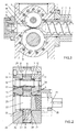
- Fig. 1
- einen Längsschnitt durch die Zahnradpumpe,
- Fig. 2
- einen Querschnitt durch die Zahnradpumpe,
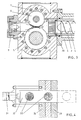
- Fig. 3
- einen Querschnitt durch eine Zahnradpumpe mit Strainer,
- Fig. 4
- einen Längsschntt durch den Strainer.
- Die Zahnradpumpe ist mit ihrem Gehäuse 1 an den Zylinder 2 des Extruders angeflanscht, welcher eine Büchse 3 aufnimmt, in welcher die Extruderschnecke 4 rotierend die Kautschukmischung fördert und plastifiziert. Im Inneren des Gehäuses 1 der Zahnradpumpe rotieren zwei Zahnräder 5,6 und fördern das Extrudat vom Eingangskanal 7 in den Austrittskanal 8 und von dort in den Spritzkopf 9, welcher an das Gehäuse 1 angeflanscht ist. In den zu den Stirnseiten der Zahnräder 5,6 parallelen Wandungen des Austrittskanales 8 ist eine Vertiefung 10 eingearbeitet, um zwischen den Zähnen der Zahnräder 5,6 unter hohen Druck gesetztes Fördergut in den Austrittskanal hineinfördern zu können.
- Wie aus Fig. 2 ersichtlich, sind an den Stirnseiten der Zahnräder 5,6 Förderspiralen 11 und an den wellenförmigen bzw. hohlzapfenförmigen Teilen Fördergewinde 12 angeordnet. Diese Förderspiralen 11 und Fördergewinde 12 dienen der Rückförderung, und zwar die Förderspiralen 11 der Rückführung von Leckfördergut und das Fördergewinde 12 für die Rückführung von Schmiermittel. Unter den hohen Drucken, die sowohl im Förderraum auftreten, als auch die das Schmiermittel beaufschlagen, können diese Arbeitsmittel weder das Fördergut noch das Schmiermittel vollständig zurückführen, sie sollen es auch nicht. Sowohl für die Reinhaltung des Schmiermittels als auch für die Reinhaltung des Fördergutes ist es nämlich vorteilhaft, wenn ein Teil der Leckströmung nach außen abgeführt wird. Hierzu dienen Kanäle 13, die zweckmäßigerweise noch mit einer im Gehäuse angeordneten Rille verbunden sein können.
- Die Wirkung der Dichtspiralen und Dichtgewinde kann entscheidend durch Einpressen von mischungsverträglichen Bestandteilen, z.B. bestimmter Thermoplaste, vorzugsweise Polyäthylen, z.B. mit einer Dosierpumpe in den Bereich der Dichtspiralen oder -gewinde verbessert werden. In manchen Fällen kann dann auf die Leckauslässe verzichtet werden.
- Das kleinere Zahnrad 6 ist auf einem Bolzen 14 gelagert, der mehrere Abschnitte unterschiedlichen Durchmessers aufweist. Zwischen dem mittleren Abschnitt dieses Bolzens 14 und den Innenwandungen des Zahnrades 6 sind Nadeln 15 eines Nadellagers in vier parallelen Reihen angeordnet. Am einen Ende weist dieser Bolzen 14 einen Flansch 16 auf, welcher mittels Schrauben 17 im Gehäuse 1 befestigt ist. An seinem anderen Ende trägt der Bolzen 14 ein Gewinde, auf welches eine Mutter 18 aufgeschraubt ist, welche in eine Ausnehmung des Gehäuses 1 eingreift.
- Das Zahnrad 5 größeren Durchmessers ist mit der Antriebswelle 19 verbunden oder es ist einstückig mit dieser Antriebswelle hergestellt. Diese Welle 19 ist im Bereich unterhalb der Zähne 20 mit einem Hohlraum 21 versehen, in welchen ein Lagerzapfen 22 eingreift. Dieser Lagerzapfen 22 ist abgestuft ausgebildet, mit seinem mittleren Teil sitzt er in einem Paßsitz im Gehäuse 1, sein eines Ende ist als Flansch 23 ausgebildet und mittels Schrauben 17 im Gehäuse 1 befestigt. Der in das Innere des Gehäuses 1 hineinragende Endteil dieses Lagerzapfens 22 trägt den oder die Innenringe für Nadellager 24, welche das Zahnrad 5 lagern, welches somit direkt unter den Zähnen gelagert ist und welches somit einerseits durch die Nadellager 24, andererseits durch Nadellager 25 für die Lagerung der Welle 19 gelagert ist.
- Das Gehäuse selbst ist aus drei Teilen 26, 27, 28 aufgebaut, welche durch Schrauben 29 zusammengeklammert sind.
- In der Ausführungsform der Fig. 3 ist ein Strainersieb 30 im Eintrittskanal 7 angeordnet, welches dazu dient, Fremdkörper von den Zahnrädern 5, 6 fernzuhalten. Aus Fig. 4 ist ersichtlich, daß hier eine Siebwechselvorrichtung vorgesehen ist, nämlich ein mittels des Servomotors 31 verschiebbarer Schieber 32, welcher zwei Strainersiebe 30 aufnimmt, die wechselseitig in den Extrudatstrom eingeschoben werden können, wobei jeweils ein Sieb außerhalb des Extrudatstromes befindlich ist und hier außerhalb der Vorrichtung gereinigt oder gewechselt werden kann.
-
- 1
- Gehäuse
- 2
- Zylinder
- 3
- Büchse
- 4
- Schnecke
- 5
- Zahnrad
- 6
- Zahnrad
- 7
- Eingangskanal
- 8
- Austrittskanal
- 9
- Spritzkopf
- 10
- Vertiefung
- 11
- Förderspirale
- 12
- Fördergewinde
- 13
- Kanal
- 14
- Bolzen
- 15
- Nadel
- 16
- Flansch
- 17
- Schraube
- 18
- Mutter
- 19
- Antriebswelle
- 20
- Zahn
- 21
- Hohlraum
- 22
- Lagerzapfen
- 23
- Flansch
- 24
- Nadellager
- 25
- Nadellager
- 26
- Gehäuseteil
- 27
- Gehäuseteil
- 28
- Gehäuseteil
- 29
- Schraube
- 30
- Strainersieb
- 31
- Servomotor
- 32
- Schieber
Claims (1)
- Zahnradpumpe,
bestehend aus einem mit einem Einlaß- (7) und einem Auslaßkanal (8) versehenen Gehäuse (1) und zwei außenverzahnten Zahnrädern (5,6), deren Lager abgedichtet gegen das Fördergut im Gehäuse (1) gelagert sind, dadurch gekennzeichnet, daß die Abdichtungen (11,12) in Form einer Förder-daß spirale (11) zur Rückförderung von Fördergut an den Stirnseiten der Zahnräder (5,6) zur Trennung von Förderraum (7,8) und Lagerung der Zahnräder angeordnet sind,
daß an den wellenförmigen bzw. hohlzapfenförmigen Teilen der Zahnräder (5,6) Fördergewinde 12 für die Rückführung von Schmiermittel angeordnet sind, daß hohe Drucke das Schmiermittel beaufschlagen, und daß Kanäle 13 am Ort des Zusammentreffens von Fördergewinde (12) und Förderspirale (11) vorgesehen sind, durch die die Leckströmung des Fördergutes und des Schmiermittels nach außen abgeführt wird.
Applications Claiming Priority (2)
| Application Number | Priority Date | Filing Date | Title |
|---|---|---|---|
| DE4111218A DE4111218C2 (de) | 1991-04-07 | 1991-04-07 | Zahnradpumpe für das Fördern von schwer verarbeitbaren Kautschukmischungen |
| DE4111218 | 1991-04-07 |
Publications (3)
| Publication Number | Publication Date |
|---|---|
| EP0509218A2 EP0509218A2 (de) | 1992-10-21 |
| EP0509218A3 EP0509218A3 (en) | 1993-07-07 |
| EP0509218B1 true EP0509218B1 (de) | 1995-07-26 |
Family
ID=6428999
Family Applications (1)
| Application Number | Title | Priority Date | Filing Date |
|---|---|---|---|
| EP92103274A Expired - Lifetime EP0509218B1 (de) | 1991-04-07 | 1992-02-26 | Zahnradpumpe |
Country Status (5)
| Country | Link |
|---|---|
| US (1) | US5224838A (de) |
| EP (1) | EP0509218B1 (de) |
| JP (1) | JPH05126060A (de) |
| DE (2) | DE4111218C2 (de) |
| ES (1) | ES2078566T3 (de) |
Families Citing this family (19)
| Publication number | Priority date | Publication date | Assignee | Title |
|---|---|---|---|---|
| DE4130312C1 (de) * | 1991-09-12 | 1992-12-24 | Hermann Berstorff Maschinenbau Gmbh, 3000 Hannover, De | |
| DE9215104U1 (de) * | 1992-10-23 | 1993-01-07 | Maag Pump Systems AG, Zürich | Zahnradpumpe |
| JP2963380B2 (ja) * | 1995-11-15 | 1999-10-18 | 株式会社日本製鋼所 | 熱可塑性樹脂の造粒方法および造粒装置 |
| CZ199997A3 (cs) * | 1996-07-05 | 1998-02-18 | Paul Troester Maschinenfabrik | Dvoustupňové vytlačovací zařízení a způsob vytlačování kaučukových směsí a plastů |
| DE19826363A1 (de) * | 1998-06-12 | 1999-12-23 | Berstorff Gmbh Masch Hermann | Breitschlitzdüse zur Herstellung von Bahnen aus einem geschäumten Kunststoff |
| US6179594B1 (en) * | 1999-05-03 | 2001-01-30 | Dynisco, Inc. | Air-cooled shaft seal |
| US6213745B1 (en) | 1999-05-03 | 2001-04-10 | Dynisco | High-pressure, self-lubricating journal bearings |
| FR2828717A1 (fr) * | 2001-08-16 | 2003-02-21 | Michelin Soc Tech | Pompe a engrenage |
| US6726065B2 (en) * | 2002-02-04 | 2004-04-27 | Brian C. Sanders | Modular automatic colorant dispenser |
| EP1491800A1 (de) * | 2003-06-27 | 2004-12-29 | Parker-Hannifin Corporation | Nachgiebige Viskose-Dichtung für eine Flüssigkeitsübertragungsvorrichtung |
| CN102817832B (zh) * | 2011-06-08 | 2015-04-08 | 苏州工业园区华西泵业有限公司 | 多出口注色混合纺丝计量泵 |
| CN102817831B (zh) * | 2011-06-08 | 2015-08-26 | 苏州工业园区华西泵业有限公司 | 大容量搅拌计量泵 |
| JP5607197B2 (ja) * | 2013-03-11 | 2014-10-15 | 東洋ゴム工業株式会社 | ギアポンプの寿命予測方法及びゴム押出装置 |
| US11685095B2 (en) | 2015-06-30 | 2023-06-27 | The Goodyear Tire & Rubber Company | Method and apparatus for forming tire components using a coextruded strip |
| EP3308940B1 (de) * | 2016-10-17 | 2025-03-05 | Next Generation Analytics GmbH | Filtersystem für viskose oder hochviskose flüssigkeiten, insbesondere kunststoffschmelzen und verfahren zur filtration von viskosen oder hochviskosen flüssigkeiten |
| DE102016224445A1 (de) * | 2016-12-08 | 2018-06-14 | Robert Bosch Gmbh | Zahnradpumpe |
| IT201700067423A1 (it) * | 2017-06-16 | 2018-12-16 | Gkn Sinter Metals Ag | Disposizione di pompa e procedimento per la produzione di una disposizione di pompa. |
| US11260570B2 (en) * | 2018-05-07 | 2022-03-01 | PSI-Polymer Systems, Inc. | Filtration apparatuses and screen changer devices for polymer processing and related methods |
| US10532512B2 (en) * | 2018-06-07 | 2020-01-14 | Thermwood Corporation | Additive manufacturing apparatus |
Family Cites Families (17)
| Publication number | Priority date | Publication date | Assignee | Title |
|---|---|---|---|---|
| US642813A (en) * | 1899-04-01 | 1900-02-06 | Robert Cowen | Apparatus for cleaning rubber. |
| DE328963C (de) * | 1919-06-11 | 1920-11-11 | Daimler Motoren | Zahnradpumpe, insbesondere zur Brennstoffoerderung bei Verbrennungskraftmaschinen |
| US2767437A (en) * | 1952-02-11 | 1956-10-23 | Donald E Marshall | Method of amalgamating and extruding soap |
| US3133506A (en) * | 1961-08-15 | 1964-05-19 | Luciani Louis | Gear pump having internal bearings and seals |
| NL6504738A (de) * | 1965-04-14 | 1966-10-17 | ||
| US3331101A (en) * | 1966-08-22 | 1967-07-18 | Exxon Research Engineering Co | Shaft seal |
| DE2116091A1 (de) * | 1971-04-02 | 1972-10-19 | Robert Bosch Gmbh, 7000 Stuttgart | Vorrichtung zum Fördern von Flüssigkeiten |
| DE2238334A1 (de) * | 1972-08-04 | 1974-02-14 | Becker Kg Westhydraulik | Rotationspumpe zum foerdern von abrasiven pumpfaehigen medien bei hoeheren temperaturen, insbesondere von gussasphalt |
| SU726368A1 (ru) * | 1978-07-11 | 1980-04-05 | Предприятие П/Я Р-6956 | Роторный нагреватель |
| DE2938276A1 (de) * | 1979-09-21 | 1981-04-09 | Robert Bosch Gmbh, 7000 Stuttgart | Fluegelzellenverdichter |
| JPS56106088A (en) * | 1980-01-29 | 1981-08-24 | Matsushita Electric Ind Co Ltd | Rotary type fluid equipment |
| US4336213A (en) * | 1980-02-06 | 1982-06-22 | Fox Steve A | Plastic extrusion apparatus and method |
| GB2085081A (en) * | 1980-10-06 | 1982-04-21 | Fluid Kinetics Inc | Submersible Gear Pump for Viscous Liquids |
| US4699575A (en) * | 1986-02-12 | 1987-10-13 | Robotics, Inc. | Adhesive pump and it's control system |
| DE3609996C2 (de) * | 1986-03-25 | 1994-10-20 | Mahle Gmbh | Schraubenverdichter |
| JPS63288732A (ja) * | 1987-05-20 | 1988-11-25 | Fuji Photo Film Co Ltd | 押出成形機用フィルタ交換装置 |
| DE9011156U1 (de) * | 1990-07-28 | 1990-11-15 | Schneider, Friedhelm, 5226 Reichshof | Zahnradpumpe für hochviskose Flüssigkeiten |
-
1991
- 1991-04-07 DE DE4111218A patent/DE4111218C2/de not_active Expired - Fee Related
-
1992
- 1992-02-26 EP EP92103274A patent/EP0509218B1/de not_active Expired - Lifetime
- 1992-02-26 ES ES92103274T patent/ES2078566T3/es not_active Expired - Lifetime
- 1992-02-26 DE DE59203007T patent/DE59203007D1/de not_active Expired - Fee Related
- 1992-04-06 US US07/863,010 patent/US5224838A/en not_active Expired - Fee Related
- 1992-04-07 JP JP4114092A patent/JPH05126060A/ja active Pending
Also Published As
| Publication number | Publication date |
|---|---|
| DE4111218C2 (de) | 1995-12-21 |
| EP0509218A2 (de) | 1992-10-21 |
| JPH05126060A (ja) | 1993-05-21 |
| ES2078566T3 (es) | 1995-12-16 |
| US5224838A (en) | 1993-07-06 |
| DE59203007D1 (de) | 1995-08-31 |
| EP0509218A3 (en) | 1993-07-07 |
| DE4111218A1 (de) | 1992-10-08 |
Similar Documents
| Publication | Publication Date | Title |
|---|---|---|
| EP0509218B1 (de) | Zahnradpumpe | |
| DE2661104C2 (de) | ||
| EP2910783B1 (de) | Zweispindelige Schraubenspindelpumpe in einflutiger Bauweise | |
| EP1523403B1 (de) | Extruder | |
| DE202016103608U1 (de) | Filtervorrichtung und Reinigungseinrichtung zum Entfernen von Schmutzpartikeln von einem Filterelement einer Filtervorrichtung Filtervorrichtung und Reinigungseinrichtung zum Entfernen von Schmutzpartikeln von einem Filterelement einer Filtervorrichtung | |
| EP0955466B1 (de) | Spaltringdichtung | |
| EP2082862B1 (de) | Extruder | |
| EP1884660A1 (de) | Förderschnecke für Exzenterschneckenpumpe | |
| DE2825616C2 (de) | Lager- und Dichtungsanordnung an den Wellen einer Zahnradpumpe | |
| EP0513593B1 (de) | Vorrichtung zur Extrusion von Kunststoff- und Kautschukmischungen | |
| DE2316127A1 (de) | Exzenterschneckenpumpe | |
| DE2710236C3 (de) | Schraubenpumpe | |
| EP0642913A1 (de) | Einwellenschnecke mit Zahnradpumpe | |
| DE2856097A1 (de) | Schneckenstrangpresse fuer die verarbeitung von kunststoff, kautschuk o.dgl. | |
| EP3253554B1 (de) | Stopfschnecke | |
| DE102023102233A1 (de) | Filtervorrichtung zum Abscheiden von Verunreinigungen aus einer Polymerschmelze | |
| EP0674746B1 (de) | Taumelscheibenmaschine | |
| EP2562298A2 (de) | Spurlager für einen Spinnrotor | |
| DE102004050810A1 (de) | Einwellige, kontinuierlich arbeitende Misch- und Knetmaschine | |
| DE20212246U1 (de) | Gleitringdichtungsanordnung | |
| DE2104492B2 (de) | Schneckenstrangpresse zum foerdern, plastifizieren und mischen von thermoplastischen oder nicht vernetzten elastomeren massen | |
| AT500891B1 (de) | Richtrotorlager | |
| EP0696680B1 (de) | Zahnradpumpe zur Lackförderung | |
| DE102023128576A1 (de) | Kreiselradumpe mit ausfahrbaren Schaufeln | |
| EP1935611B1 (de) | Extruderspitze für hochviskose Stoffe |
Legal Events
| Date | Code | Title | Description |
|---|---|---|---|
| PUAI | Public reference made under article 153(3) epc to a published international application that has entered the european phase |
Free format text: ORIGINAL CODE: 0009012 |
|
| AK | Designated contracting states |
Kind code of ref document: A2 Designated state(s): CH DE ES FR GB IT LI |
|
| PUAL | Search report despatched |
Free format text: ORIGINAL CODE: 0009013 |
|
| RHK1 | Main classification (correction) |
Ipc: F04C 2/18 |
|
| AK | Designated contracting states |
Kind code of ref document: A3 Designated state(s): CH DE ES FR GB IT LI |
|
| 17P | Request for examination filed |
Effective date: 19930804 |
|
| 17Q | First examination report despatched |
Effective date: 19941109 |
|
| GRAA | (expected) grant |
Free format text: ORIGINAL CODE: 0009210 |
|
| ITF | It: translation for a ep patent filed | ||
| AK | Designated contracting states |
Kind code of ref document: B1 Designated state(s): CH DE ES FR GB IT LI |
|
| REF | Corresponds to: |
Ref document number: 59203007 Country of ref document: DE Date of ref document: 19950831 |
|
| ET | Fr: translation filed | ||
| GBT | Gb: translation of ep patent filed (gb section 77(6)(a)/1977) |
Effective date: 19951108 |
|
| REG | Reference to a national code |
Ref country code: ES Ref legal event code: FG2A Ref document number: 2078566 Country of ref document: ES Kind code of ref document: T3 |
|
| PLBE | No opposition filed within time limit |
Free format text: ORIGINAL CODE: 0009261 |
|
| STAA | Information on the status of an ep patent application or granted ep patent |
Free format text: STATUS: NO OPPOSITION FILED WITHIN TIME LIMIT |
|
| 26N | No opposition filed | ||
| PGFP | Annual fee paid to national office [announced via postgrant information from national office to epo] |
Ref country code: GB Payment date: 19980218 Year of fee payment: 7 |
|
| PGFP | Annual fee paid to national office [announced via postgrant information from national office to epo] |
Ref country code: DE Payment date: 19980219 Year of fee payment: 7 |
|
| PGFP | Annual fee paid to national office [announced via postgrant information from national office to epo] |
Ref country code: ES Payment date: 19980223 Year of fee payment: 7 |
|
| PGFP | Annual fee paid to national office [announced via postgrant information from national office to epo] |
Ref country code: FR Payment date: 19980226 Year of fee payment: 7 |
|
| PGFP | Annual fee paid to national office [announced via postgrant information from national office to epo] |
Ref country code: CH Payment date: 19980429 Year of fee payment: 7 |
|
| PG25 | Lapsed in a contracting state [announced via postgrant information from national office to epo] |
Ref country code: GB Free format text: LAPSE BECAUSE OF NON-PAYMENT OF DUE FEES Effective date: 19990226 |
|
| PG25 | Lapsed in a contracting state [announced via postgrant information from national office to epo] |
Ref country code: ES Free format text: LAPSE BECAUSE OF NON-PAYMENT OF DUE FEES Effective date: 19990227 |
|
| PG25 | Lapsed in a contracting state [announced via postgrant information from national office to epo] |
Ref country code: LI Free format text: LAPSE BECAUSE OF NON-PAYMENT OF DUE FEES Effective date: 19990228 Ref country code: CH Free format text: LAPSE BECAUSE OF NON-PAYMENT OF DUE FEES Effective date: 19990228 |
|
| GBPC | Gb: european patent ceased through non-payment of renewal fee |
Effective date: 19990226 |
|
| REG | Reference to a national code |
Ref country code: CH Ref legal event code: PL |
|
| PG25 | Lapsed in a contracting state [announced via postgrant information from national office to epo] |
Ref country code: FR Free format text: LAPSE BECAUSE OF NON-PAYMENT OF DUE FEES Effective date: 19991029 |
|
| PG25 | Lapsed in a contracting state [announced via postgrant information from national office to epo] |
Ref country code: DE Free format text: LAPSE BECAUSE OF NON-PAYMENT OF DUE FEES Effective date: 19991201 |
|
| REG | Reference to a national code |
Ref country code: FR Ref legal event code: ST |
|
| REG | Reference to a national code |
Ref country code: ES Ref legal event code: FD2A Effective date: 20010910 |
|
| PG25 | Lapsed in a contracting state [announced via postgrant information from national office to epo] |
Ref country code: IT Free format text: LAPSE BECAUSE OF NON-PAYMENT OF DUE FEES Effective date: 20050226 |