EP0508570A2 - Permanentmagnetwandler - Google Patents
Permanentmagnetwandler Download PDFInfo
- Publication number
- EP0508570A2 EP0508570A2 EP92301397A EP92301397A EP0508570A2 EP 0508570 A2 EP0508570 A2 EP 0508570A2 EP 92301397 A EP92301397 A EP 92301397A EP 92301397 A EP92301397 A EP 92301397A EP 0508570 A2 EP0508570 A2 EP 0508570A2
- Authority
- EP
- European Patent Office
- Prior art keywords
- transducer
- permanent magnet
- core
- input
- signal
- Prior art date
- Legal status (The legal status is an assumption and is not a legal conclusion. Google has not performed a legal analysis and makes no representation as to the accuracy of the status listed.)
- Granted
Links
Images


Classifications
-
- H—ELECTRICITY
- H04—ELECTRIC COMMUNICATION TECHNIQUE
- H04R—LOUDSPEAKERS, MICROPHONES, GRAMOPHONE PICK-UPS OR LIKE ACOUSTIC ELECTROMECHANICAL TRANSDUCERS; ELECTRIC HEARING AIDS; PUBLIC ADDRESS SYSTEMS
- H04R3/00—Circuits for transducers
- H04R3/002—Damping circuit arrangements for transducers, e.g. motional feedback circuits
-
- H—ELECTRICITY
- H04—ELECTRIC COMMUNICATION TECHNIQUE
- H04R—LOUDSPEAKERS, MICROPHONES, GRAMOPHONE PICK-UPS OR LIKE ACOUSTIC ELECTROMECHANICAL TRANSDUCERS; ELECTRIC HEARING AIDS; PUBLIC ADDRESS SYSTEMS
- H04R9/00—Transducers of moving-coil, moving-strip, or moving-wire type
- H04R9/02—Details
- H04R9/025—Magnetic circuit
Definitions
- the present invention relates in general to permanent magnet transducing and more particularly concerns novel apparatus and techniques for exchanging mechanical and electrical energy using a permanent magnet and relatively movable coil on a low reluctance magnetic core.
- Typical prior art moving magnet electromechanical transducers are disclosed in U.S. Patent Nos. 3,798,391, 3,917,914 and 3,937,904.
- the latter patent discloses a transducer having a U-shaped core of magnetically permeable material with attached pole pieces defining a gap and a stationary electrical coil on the bight of the U-shaped core far from the gap.
- a permanent magnet is positioned for movement through the central portion of the gap in the plane of the U-shaped core toward and away from the coil on the bight.
- the permanent magnet has diagonally positioned poles of like magnetic orientation to provide a north-south pole combination facing one of the pole pieces and a complementary south-north pole combination facing the other pole piece.
- a core of low reluctance magnetic material formed with a narrow gap.
- first and second coils of conductive material wound on the core adjacent to and on opposite sides of the gap.
- a permanent magnet in and substantially filling the gap is in noncontacting relationship with the core and supported to allow relative movement between the permanent magnet and the core.
- the core may be generally U-shaped, C-shaped or 8-shaped with the path of relative movement between the permanent magnet and the core usually generally perpendicular to the plane of the core. No portion of the core is in the plane of permanent magnet movement.
- the permanent magnet preferably comprises first and second contiguous permanent magnet elements having adjacent unlike poles along a boundary substantially midway between opposed surfaces of the core along the direction of relative motion.
- a diaphragm connected to the permanent magnet whereby an electrical signal may be applied to the first and second windings to produce a corresponding magnetic field in the gap causing corresponding relative displacement between the permanent magnet and the core and corresponding relative displacement of the diaphragm.
- a combiner having a signal input, a feedback input and an output for providing a combined signal related to the combination of signals on said signal input and said feedback input.
- a controlled signal source having an input coupled to the combiner output and an output coupled to at least one of the windings providing a controlled signal.
- a feedback circuit intercoupling the transducer and the feedback input, preferably providing a feedback signal related to at least one of velocity and acceleration of the permanent magnet assembly, or voltage and current in the windings.
- FIG. 1 there is shown a perspective view of a transducer according to the invention.
- a C-shaped core 11 of material of low magnetic reluctance, such as soft iron, carries a first winding 12 and second winding 13 of conducting material wound on legs 11A and 11B closely adjacent to gap 14 substantially filled by permanent magnets 15 and 16 seated in movable magnet support 17.
- Permanent magnets 15 and 16 have adjacent unlike poles, the boundary between the poles being located midway, along the direction of relative motion 18, between opposed surfaces of core 11, when the current through windings 12 and 13 is substantially zero and with no other external force applied.
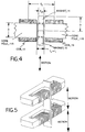
- FIG. 2 there is shown an axial sectional view of a loudspeaker driver incorporating the transducer of FIG. 1.
- the same reference symbols identify corresponding elements throughout the drawing.
- Loudspeaker basket 21 which may be metal, plastic or other suitable material, anchors the edge of loudspeaker cone or diaphragm 22, to spider suspension elements 23 and 24 at opposite ends of the basket portion that encloses the transducer of FIG. 1 with core 11 seated in a wall of basket 21 as shown.
- One end of permanent magnet support 17 is connected to spider suspension element 24 and the other end to spider suspension element 23 and cone or diaphragm 22.
- the rectangular magnet assembly comprises permanent magnet support 17 and rectangular magnets 15 and 16 having reversed polarity of magnetization suspended in the center of gap 14 of C-shaped core 11. Coils 12 and 13 are connected in series and polarized so that the magnetic fields produced by current flowing through them adds constructively.
- FIG. 3 there is shown an idealized electrical circuit equivalent model of the transducer of FIGS. 1 and 2.
- This model comprises transformer 30, resistance 31, inductance 32 and capacitance 33.
- Inductance 32 and capacitance 33 may be regarded as elements which limit the bandwidth of the transducer.
- the minimum mass of the moving magnets 15 and 16 is defined by the mechanical work produced by (or applied to) the transducer.
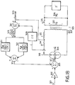
- FIG. 13 there is shown an idealized electrical model of a prior art speaker and its drive.
- An electrical audio signal on input 101 to be reproduced energizes amplifier 102 to provide an amplified audio signal that is applied to the input terminals 115 of the transducer.
- Current flows through the electrical resistance 103 and inductance 104 of the loudspeaker motor and is coupled to the mechanical motion of the cone through transformer 105.
- the moving mass of the loudspeaker motor is modeled as capacitor 106 and the coupling from the cone to the enclosure 108 is performed through cone area transformer 107. It is convenient to combine the load modeling acoustic enclosure 108 with cone area transformer 107 to form an equivalent impedance Z′ 114.
- driving the motor with a switched mode power amplifier such as disclosed in U.S. Patent Nos. 3,294,981 and 4, 456,872, incorporated herein by reference, and using active feedback allows the use of high ⁇ motors while maintaining the desired system acoustic performance.
Landscapes
- Physics & Mathematics (AREA)
- Engineering & Computer Science (AREA)
- Acoustics & Sound (AREA)
- Signal Processing (AREA)
- Audible-Bandwidth Dynamoelectric Transducers Other Than Pickups (AREA)
- Gyroscopes (AREA)
- Optical Head (AREA)
- Telephone Function (AREA)
- Electrostatic, Electromagnetic, Magneto- Strictive, And Variable-Resistance Transducers (AREA)
- Magnetic Resonance Imaging Apparatus (AREA)
- Measuring Magnetic Variables (AREA)
- Inductance-Capacitance Distribution Constants And Capacitance-Resistance Oscillators (AREA)
Applications Claiming Priority (2)
| Application Number | Priority Date | Filing Date | Title |
|---|---|---|---|
| US07/667,461 US5216723A (en) | 1991-03-11 | 1991-03-11 | Permanent magnet transducing |
| US667461 | 1991-03-11 |
Publications (3)
| Publication Number | Publication Date |
|---|---|
| EP0508570A2 true EP0508570A2 (de) | 1992-10-14 |
| EP0508570A3 EP0508570A3 (en) | 1993-08-04 |
| EP0508570B1 EP0508570B1 (de) | 1995-12-20 |
Family
ID=24678317
Family Applications (1)
| Application Number | Title | Priority Date | Filing Date |
|---|---|---|---|
| EP92301397A Expired - Lifetime EP0508570B1 (de) | 1991-03-11 | 1992-02-20 | Permanentmagnetwandler |
Country Status (6)
| Country | Link |
|---|---|
| US (1) | US5216723A (de) |
| EP (1) | EP0508570B1 (de) |
| JP (1) | JPH0591592A (de) |
| AT (1) | ATE131991T1 (de) |
| CA (1) | CA2061444A1 (de) |
| DE (1) | DE69206863T2 (de) |
Cited By (6)
| Publication number | Priority date | Publication date | Assignee | Title |
|---|---|---|---|---|
| WO2011123265A1 (en) * | 2010-03-31 | 2011-10-06 | Bose Corporation | Moving magnet levered loudspeaker |
| US8295537B2 (en) | 2010-03-31 | 2012-10-23 | Bose Corporation | Loudspeaker moment and torque balancing |
| US9055370B2 (en) | 2012-08-31 | 2015-06-09 | Bose Corporation | Vibration-reducing passive radiators |
| WO2021150278A1 (en) * | 2020-01-21 | 2021-07-29 | Clean Energy Labs, Llc | Electroacoustic drivers and loudspeakers containing same |
| IT202100032897A1 (it) | 2021-12-29 | 2023-06-29 | Powersoft S P A | Trasduttore per un diffusore acustico e metodo per la produzione del trasduttore. |
| EP4207809A1 (de) | 2021-12-29 | 2023-07-05 | Powersoft SpA | Schalldiffusor und verfahren zur diffusion eines schalls durch einen schalldiffusor |
Families Citing this family (35)
| Publication number | Priority date | Publication date | Assignee | Title |
|---|---|---|---|---|
| US5991423A (en) * | 1998-09-21 | 1999-11-23 | Lucent Technologies Inc. | Planar magnetic continuous-tone transducer |
| US6405599B1 (en) * | 2000-01-13 | 2002-06-18 | Bose Corporation | Frictionless motor material testing |
| AU2003215342A1 (en) | 2002-02-21 | 2003-09-09 | Design Mentor, Inc. | Fluid pump |
| US6945541B2 (en) * | 2003-01-21 | 2005-09-20 | Bose Corporation | Vehicle suspension |
| US6926288B2 (en) * | 2003-06-02 | 2005-08-09 | Bose Corporation | Electromagnetic interference filter |
| US7219684B2 (en) * | 2005-01-28 | 2007-05-22 | Rain Bird Corporation | Saddle tee and tool for irrigation lines |
| US8224009B2 (en) * | 2007-03-02 | 2012-07-17 | Bose Corporation | Audio system with synthesized positive impedance |
| US7726193B2 (en) * | 2007-09-27 | 2010-06-01 | Baker Hughes Incorporated | Electromagnetic acoustic transducer with cross-talk elimination |
| DE102009052129A1 (de) | 2009-11-05 | 2011-05-12 | Technische Universität Dresden | Wandler mit mindestens einem bewegten Dauermagnet |
| US20120248898A1 (en) * | 2011-03-29 | 2012-10-04 | Richard Tucker Carlmark | Moving Magnet Actuator Magnet Carrier |
| US8610318B2 (en) * | 2011-03-29 | 2013-12-17 | Bose Corporation | Moving magnet actuator magnet carrier |
| US20120280579A1 (en) * | 2011-05-06 | 2012-11-08 | Bose Corporation | Linear moving magnet motor cogging force ripple reducing |
| US9606035B2 (en) | 2011-12-21 | 2017-03-28 | Ta Instruments-Waters Llc | System for mechanical stimulation and characterization of biologic samples |
| US9496778B2 (en) | 2012-08-22 | 2016-11-15 | Ta Instruments-Waters L.L.C. | Electromagnetic motor |
| US10028062B2 (en) * | 2013-03-15 | 2018-07-17 | Bose Corporation | Driving plural armatures with a common stator |
| ES2908079T3 (es) * | 2013-06-14 | 2022-04-27 | Genelec Oy | Elemento de suspensión para suspender el diafragma de un controlador de altavoz a su chasis, así como un controlador y altavoz que comprenden dicho elemento |
| EP2914018B1 (de) * | 2014-02-26 | 2016-11-09 | Sonion Nederland B.V. | Lautsprecher, verankerung und verfahren |
| US9357279B2 (en) | 2014-03-07 | 2016-05-31 | Bose Corporation | Elastomeric torsion bushings for levered loudspeakers |
| US9258648B2 (en) | 2014-03-07 | 2016-02-09 | Bose Corporation | Levered loudspeakers |
| US9601969B2 (en) | 2014-03-07 | 2017-03-21 | Bose Corporation | Inhibiting rocking of loads driven by plural levers |
| US9497549B2 (en) | 2014-03-07 | 2016-11-15 | Bose Corporation | Levered loudspeakers |
| US9130445B1 (en) * | 2014-08-04 | 2015-09-08 | David Micah Katz | Electromechanical transducer with non-circular voice coil |
| CN204733374U (zh) * | 2015-06-23 | 2015-10-28 | 瑞声光电科技(常州)有限公司 | 扬声器 |
| CN204741558U (zh) * | 2015-06-23 | 2015-11-04 | 瑞声光电科技(常州)有限公司 | 扬声器 |
| US10154347B2 (en) | 2015-10-23 | 2018-12-11 | Bose Corporation | Bushings constrained by compression in levered apparatus |
| US11040682B1 (en) | 2016-03-21 | 2021-06-22 | Paradigm Research and Engineering, LLC | Blast detection and safety deployment system and method for using the same |
| TWI610576B (zh) * | 2016-08-15 | 2018-01-01 | 緯創資通股份有限公司 | 揚聲器 |
| US10084410B2 (en) * | 2016-12-15 | 2018-09-25 | Bose Corporation | Moving magnet motor and transducer with moving magnet motor |
| US11778385B2 (en) * | 2017-06-23 | 2023-10-03 | Cochlear Limited | Electromagnetic transducer with non-axial air gap |
| CN109803216B (zh) * | 2019-01-15 | 2020-11-20 | 哈尔滨工程大学 | 一种动磁式直线致动器 |
| PH22020050740U3 (en) * | 2019-12-30 | 2023-07-26 | Knowles Electronics Llc | Acoustic receiver with coils and a terminal board |
| US11600435B2 (en) | 2020-12-31 | 2023-03-07 | Knowles Electronics, Llc | Coil bobbin for a balanced armature receiver |
| US11889284B2 (en) * | 2021-03-25 | 2024-01-30 | Sound Solutions International Co., Ltd. | Multi magnet electrodynamic acoustic transducer and electroacoustic system |
| US12532127B2 (en) * | 2021-07-19 | 2026-01-20 | Brane Audio, LLC | Electroacoustic drivers and loudspeakers containing same |
| US12306018B1 (en) | 2022-11-22 | 2025-05-20 | St3 Development Corporation | Material testing apparatus having vibration mitigation |
Family Cites Families (8)
| Publication number | Priority date | Publication date | Assignee | Title |
|---|---|---|---|---|
| US2026994A (en) * | 1929-05-15 | 1936-01-07 | Messick Charles | Armature for magnetic movements |
| US3062926A (en) * | 1959-03-20 | 1962-11-06 | John J Ronci | Magnet with vibratable armature |
| US3937904A (en) * | 1974-08-07 | 1976-02-10 | Hitachi Magnetics Corporation | Moving magnet electroacoustic transducer |
| US4020361A (en) * | 1974-10-04 | 1977-04-26 | Delta Electronic Control Corporation | Switching mode power controller of large dynamic range |
| DE3313333A1 (de) * | 1983-04-13 | 1984-10-18 | Battelle-Institut E.V., 6000 Frankfurt | Vorrichtung zur erzeugung von magnetischen kraeften |
| GB2149272B (en) * | 1983-10-26 | 1987-06-17 | Adam Kovacs | Electromechanical transducer |
| DE3527501A1 (de) * | 1984-09-03 | 1986-03-13 | Sanden Corp., Isesaki, Gunma | Dynamische wandlereinrichtung |
| US5009281A (en) * | 1988-03-10 | 1991-04-23 | Yamaha Corporation | Acoustic apparatus |
-
1991
- 1991-03-11 US US07/667,461 patent/US5216723A/en not_active Expired - Lifetime
-
1992
- 1992-02-18 CA CA002061444A patent/CA2061444A1/en not_active Abandoned
- 1992-02-20 EP EP92301397A patent/EP0508570B1/de not_active Expired - Lifetime
- 1992-02-20 DE DE69206863T patent/DE69206863T2/de not_active Expired - Lifetime
- 1992-02-20 AT AT92301397T patent/ATE131991T1/de not_active IP Right Cessation
- 1992-03-06 JP JP4050013A patent/JPH0591592A/ja active Pending
Cited By (16)
| Publication number | Priority date | Publication date | Assignee | Title |
|---|---|---|---|---|
| WO2011123265A1 (en) * | 2010-03-31 | 2011-10-06 | Bose Corporation | Moving magnet levered loudspeaker |
| US8295536B2 (en) | 2010-03-31 | 2012-10-23 | Bose Corporation | Moving magnet levered loudspeaker |
| US8295537B2 (en) | 2010-03-31 | 2012-10-23 | Bose Corporation | Loudspeaker moment and torque balancing |
| US9055370B2 (en) | 2012-08-31 | 2015-06-09 | Bose Corporation | Vibration-reducing passive radiators |
| US12003943B2 (en) | 2020-01-21 | 2024-06-04 | Brane Audio, LLC | Electroacoustic drivers and loudspeakers containing same |
| US12003942B2 (en) | 2020-01-21 | 2024-06-04 | Brane Audio, LLC | Electroacoustic drivers and loudspeakers containing same |
| WO2021150278A1 (en) * | 2020-01-21 | 2021-07-29 | Clean Energy Labs, Llc | Electroacoustic drivers and loudspeakers containing same |
| US12003940B2 (en) | 2020-01-21 | 2024-06-04 | Brane Audio, LLC | Electroacoustic drivers and loudspeakers containing same |
| US12003941B2 (en) | 2020-01-21 | 2024-06-04 | Brane Audio, LLC | Electroacoustic drivers and loudspeakers containing same |
| US12126979B2 (en) | 2020-01-21 | 2024-10-22 | Brane Audio, LLC | Electroacoustic drivers and loudspeakers containing same |
| US12256207B2 (en) | 2020-01-21 | 2025-03-18 | Brane Audio, LLC | Electroacoustic drivers and loudspeakers containing same |
| US12284507B2 (en) | 2020-01-21 | 2025-04-22 | Brane Audio, LLC | Force transducers for electroacoustic drivers and loudspeakers containing same |
| IT202100032897A1 (it) | 2021-12-29 | 2023-06-29 | Powersoft S P A | Trasduttore per un diffusore acustico e metodo per la produzione del trasduttore. |
| EP4207809A1 (de) | 2021-12-29 | 2023-07-05 | Powersoft SpA | Schalldiffusor und verfahren zur diffusion eines schalls durch einen schalldiffusor |
| EP4539503A2 (de) | 2021-12-29 | 2025-04-16 | Powersoft SpA | Schalldiffusor und verfahren zur diffusion eines schalls durch einen schalldiffusor |
| US12309566B2 (en) | 2021-12-29 | 2025-05-20 | Powersoft S.P.A. | Sound diffuser and a method for diffusing a sound through a sound diffuser |
Also Published As
| Publication number | Publication date |
|---|---|
| ATE131991T1 (de) | 1996-01-15 |
| DE69206863T2 (de) | 1996-05-15 |
| EP0508570B1 (de) | 1995-12-20 |
| EP0508570A3 (en) | 1993-08-04 |
| US5216723A (en) | 1993-06-01 |
| JPH0591592A (ja) | 1993-04-09 |
| CA2061444A1 (en) | 1992-09-12 |
| DE69206863D1 (de) | 1996-02-01 |
Similar Documents
| Publication | Publication Date | Title |
|---|---|---|
| EP0508570B1 (de) | Permanentmagnetwandler | |
| US4327257A (en) | Alignment device for electro-acoustical transducers | |
| US8385583B2 (en) | Methods and apparatus for reduced distortion balanced armature devices | |
| EP0799520B1 (de) | Elektromagnetischer krafterzeuger | |
| US4273968A (en) | Electroacoustic transducer with magnetic flux directed slantly across a diaphragm | |
| US20050031154A1 (en) | Electromagnetic transducer having multiple magnetic air gaps whose magnetic flux is in a same direction | |
| EP0548579B1 (de) | Ausgewogene Armaturwandler mit transversalem Zwischenraum | |
| US7039213B2 (en) | Speaker driver | |
| AU2009242055B2 (en) | Ironless and leakage free coil transducer motor assembly | |
| US7873180B2 (en) | Voice coil actuator | |
| JP2009278523A (ja) | スピーカ | |
| JP2022161138A (ja) | ボイスコイルモータ | |
| KR20060014662A (ko) | 스피커의 보이스코일 구조 | |
| US20020080991A1 (en) | Universal ribbon element-module for two or more membrane-widths with optimized flow and drive | |
| KR102146285B1 (ko) | 스피커 | |
| JP3458922B2 (ja) | ボイスコイル形リニアモータ | |
| JP3961960B2 (ja) | スピーカ | |
| JP2001186589A (ja) | スピーカユニット | |
| Leung et al. | An application of linear motor to loudspeaker systems | |
| WO2005010902A1 (ja) | 限流器 | |
| JPH0759195A (ja) | スピーカ | |
| JPS61167368A (ja) | リニア直流モ−タ | |
| JPS6119600Y2 (de) | ||
| KR800000764B1 (ko) | 전동형 픽업(pickup) | |
| Merit et al. | An ironless low frequency subwoofer functioning under its resonance frequency. |
Legal Events
| Date | Code | Title | Description |
|---|---|---|---|
| PUAI | Public reference made under article 153(3) epc to a published international application that has entered the european phase |
Free format text: ORIGINAL CODE: 0009012 |
|
| AK | Designated contracting states |
Kind code of ref document: A2 Designated state(s): AT BE CH DE DK ES FR GB GR IT LI LU NL PT SE |
|
| PUAL | Search report despatched |
Free format text: ORIGINAL CODE: 0009013 |
|
| AK | Designated contracting states |
Kind code of ref document: A3 Designated state(s): AT BE CH DE DK ES FR GB GR IT LI LU NL PT SE |
|
| 17P | Request for examination filed |
Effective date: 19940201 |
|
| 17Q | First examination report despatched |
Effective date: 19940620 |
|
| GRAA | (expected) grant |
Free format text: ORIGINAL CODE: 0009210 |
|
| AK | Designated contracting states |
Kind code of ref document: B1 Designated state(s): AT BE CH DE DK ES FR GB GR IT LI LU NL PT SE |
|
| PG25 | Lapsed in a contracting state [announced via postgrant information from national office to epo] |
Ref country code: IT Free format text: LAPSE BECAUSE OF FAILURE TO SUBMIT A TRANSLATION OF THE DESCRIPTION OR TO PAY THE FEE WITHIN THE PRE;WARNING: LAPSES OF ITALIAN PATENTS WITH EFFECTIVE DATE BEFORE 2007 MAY HAVE OCCURRED AT ANY TIME BEFORE 2007. THE CORRECT EFFECTIVE DATE MAY BE DIFFERENT FROM THE ONE RECORDED.SCRIBED TIME-LIMIT Effective date: 19951220 Ref country code: CH Free format text: LAPSE BECAUSE OF FAILURE TO SUBMIT A TRANSLATION OF THE DESCRIPTION OR TO PAY THE FEE WITHIN THE PRESCRIBED TIME-LIMIT Effective date: 19951220 Ref country code: LI Free format text: LAPSE BECAUSE OF FAILURE TO SUBMIT A TRANSLATION OF THE DESCRIPTION OR TO PAY THE FEE WITHIN THE PRESCRIBED TIME-LIMIT Effective date: 19951220 Ref country code: DK Effective date: 19951220 Ref country code: FR Effective date: 19951220 Ref country code: GR Free format text: LAPSE BECAUSE OF FAILURE TO SUBMIT A TRANSLATION OF THE DESCRIPTION OR TO PAY THE FEE WITHIN THE PRESCRIBED TIME-LIMIT Effective date: 19951220 Ref country code: ES Free format text: THE PATENT HAS BEEN ANNULLED BY A DECISION OF A NATIONAL AUTHORITY Effective date: 19951220 Ref country code: NL Free format text: LAPSE BECAUSE OF FAILURE TO SUBMIT A TRANSLATION OF THE DESCRIPTION OR TO PAY THE FEE WITHIN THE PRESCRIBED TIME-LIMIT Effective date: 19951220 Ref country code: BE Effective date: 19951220 Ref country code: AT Effective date: 19951220 |
|
| REF | Corresponds to: |
Ref document number: 131991 Country of ref document: AT Date of ref document: 19960115 Kind code of ref document: T |
|
| REF | Corresponds to: |
Ref document number: 69206863 Country of ref document: DE Date of ref document: 19960201 |
|
| PG25 | Lapsed in a contracting state [announced via postgrant information from national office to epo] |
Ref country code: LU Free format text: LAPSE BECAUSE OF NON-PAYMENT OF DUE FEES Effective date: 19960229 |
|
| PG25 | Lapsed in a contracting state [announced via postgrant information from national office to epo] |
Ref country code: SE Effective date: 19960320 Ref country code: PT Effective date: 19960320 |
|
| EN | Fr: translation not filed | ||
| NLV1 | Nl: lapsed or annulled due to failure to fulfill the requirements of art. 29p and 29m of the patents act | ||
| PLBE | No opposition filed within time limit |
Free format text: ORIGINAL CODE: 0009261 |
|
| 26N | No opposition filed | ||
| REG | Reference to a national code |
Ref country code: GB Ref legal event code: IF02 |
|
| PGFP | Annual fee paid to national office [announced via postgrant information from national office to epo] |
Ref country code: DE Payment date: 20110225 Year of fee payment: 20 |
|
| PGFP | Annual fee paid to national office [announced via postgrant information from national office to epo] |
Ref country code: GB Payment date: 20110223 Year of fee payment: 20 |
|
| REG | Reference to a national code |
Ref country code: DE Ref legal event code: R071 Ref document number: 69206863 Country of ref document: DE |
|
| REG | Reference to a national code |
Ref country code: DE Ref legal event code: R071 Ref document number: 69206863 Country of ref document: DE |
|
| REG | Reference to a national code |
Ref country code: GB Ref legal event code: PE20 Expiry date: 20120219 |
|
| PG25 | Lapsed in a contracting state [announced via postgrant information from national office to epo] |
Ref country code: DE Free format text: LAPSE BECAUSE OF EXPIRATION OF PROTECTION Effective date: 20120221 |
|
| PG25 | Lapsed in a contracting state [announced via postgrant information from national office to epo] |
Ref country code: GB Free format text: LAPSE BECAUSE OF EXPIRATION OF PROTECTION Effective date: 20120219 |