EP0508570A2 - Permanent magnet transducer - Google Patents
Permanent magnet transducer Download PDFInfo
- Publication number
- EP0508570A2 EP0508570A2 EP92301397A EP92301397A EP0508570A2 EP 0508570 A2 EP0508570 A2 EP 0508570A2 EP 92301397 A EP92301397 A EP 92301397A EP 92301397 A EP92301397 A EP 92301397A EP 0508570 A2 EP0508570 A2 EP 0508570A2
- Authority
- EP
- European Patent Office
- Prior art keywords
- transducer
- permanent magnet
- core
- input
- signal
- Prior art date
- Legal status (The legal status is an assumption and is not a legal conclusion. Google has not performed a legal analysis and makes no representation as to the accuracy of the status listed.)
- Granted
Links
Images


Classifications
-
- H—ELECTRICITY
- H04—ELECTRIC COMMUNICATION TECHNIQUE
- H04R—LOUDSPEAKERS, MICROPHONES, GRAMOPHONE PICK-UPS OR LIKE ACOUSTIC ELECTROMECHANICAL TRANSDUCERS; ELECTRIC HEARING AIDS; PUBLIC ADDRESS SYSTEMS
- H04R3/00—Circuits for transducers
- H04R3/002—Damping circuit arrangements for transducers, e.g. motional feedback circuits
-
- H—ELECTRICITY
- H04—ELECTRIC COMMUNICATION TECHNIQUE
- H04R—LOUDSPEAKERS, MICROPHONES, GRAMOPHONE PICK-UPS OR LIKE ACOUSTIC ELECTROMECHANICAL TRANSDUCERS; ELECTRIC HEARING AIDS; PUBLIC ADDRESS SYSTEMS
- H04R9/00—Transducers of moving-coil, moving-strip, or moving-wire type
- H04R9/02—Details
- H04R9/025—Magnetic circuit
Definitions
- the present invention relates in general to permanent magnet transducing and more particularly concerns novel apparatus and techniques for exchanging mechanical and electrical energy using a permanent magnet and relatively movable coil on a low reluctance magnetic core.
- Typical prior art moving magnet electromechanical transducers are disclosed in U.S. Patent Nos. 3,798,391, 3,917,914 and 3,937,904.
- the latter patent discloses a transducer having a U-shaped core of magnetically permeable material with attached pole pieces defining a gap and a stationary electrical coil on the bight of the U-shaped core far from the gap.
- a permanent magnet is positioned for movement through the central portion of the gap in the plane of the U-shaped core toward and away from the coil on the bight.
- the permanent magnet has diagonally positioned poles of like magnetic orientation to provide a north-south pole combination facing one of the pole pieces and a complementary south-north pole combination facing the other pole piece.
- a core of low reluctance magnetic material formed with a narrow gap.
- first and second coils of conductive material wound on the core adjacent to and on opposite sides of the gap.
- a permanent magnet in and substantially filling the gap is in noncontacting relationship with the core and supported to allow relative movement between the permanent magnet and the core.
- the core may be generally U-shaped, C-shaped or 8-shaped with the path of relative movement between the permanent magnet and the core usually generally perpendicular to the plane of the core. No portion of the core is in the plane of permanent magnet movement.
- the permanent magnet preferably comprises first and second contiguous permanent magnet elements having adjacent unlike poles along a boundary substantially midway between opposed surfaces of the core along the direction of relative motion.
- a diaphragm connected to the permanent magnet whereby an electrical signal may be applied to the first and second windings to produce a corresponding magnetic field in the gap causing corresponding relative displacement between the permanent magnet and the core and corresponding relative displacement of the diaphragm.
- a combiner having a signal input, a feedback input and an output for providing a combined signal related to the combination of signals on said signal input and said feedback input.
- a controlled signal source having an input coupled to the combiner output and an output coupled to at least one of the windings providing a controlled signal.
- a feedback circuit intercoupling the transducer and the feedback input, preferably providing a feedback signal related to at least one of velocity and acceleration of the permanent magnet assembly, or voltage and current in the windings.
- FIG. 1 there is shown a perspective view of a transducer according to the invention.
- a C-shaped core 11 of material of low magnetic reluctance, such as soft iron, carries a first winding 12 and second winding 13 of conducting material wound on legs 11A and 11B closely adjacent to gap 14 substantially filled by permanent magnets 15 and 16 seated in movable magnet support 17.
- Permanent magnets 15 and 16 have adjacent unlike poles, the boundary between the poles being located midway, along the direction of relative motion 18, between opposed surfaces of core 11, when the current through windings 12 and 13 is substantially zero and with no other external force applied.
- FIG. 2 there is shown an axial sectional view of a loudspeaker driver incorporating the transducer of FIG. 1.
- the same reference symbols identify corresponding elements throughout the drawing.
- Loudspeaker basket 21 which may be metal, plastic or other suitable material, anchors the edge of loudspeaker cone or diaphragm 22, to spider suspension elements 23 and 24 at opposite ends of the basket portion that encloses the transducer of FIG. 1 with core 11 seated in a wall of basket 21 as shown.
- One end of permanent magnet support 17 is connected to spider suspension element 24 and the other end to spider suspension element 23 and cone or diaphragm 22.
- the rectangular magnet assembly comprises permanent magnet support 17 and rectangular magnets 15 and 16 having reversed polarity of magnetization suspended in the center of gap 14 of C-shaped core 11. Coils 12 and 13 are connected in series and polarized so that the magnetic fields produced by current flowing through them adds constructively.
- FIG. 3 there is shown an idealized electrical circuit equivalent model of the transducer of FIGS. 1 and 2.
- This model comprises transformer 30, resistance 31, inductance 32 and capacitance 33.
- Inductance 32 and capacitance 33 may be regarded as elements which limit the bandwidth of the transducer.
- the minimum mass of the moving magnets 15 and 16 is defined by the mechanical work produced by (or applied to) the transducer.
- FIG. 13 there is shown an idealized electrical model of a prior art speaker and its drive.
- An electrical audio signal on input 101 to be reproduced energizes amplifier 102 to provide an amplified audio signal that is applied to the input terminals 115 of the transducer.
- Current flows through the electrical resistance 103 and inductance 104 of the loudspeaker motor and is coupled to the mechanical motion of the cone through transformer 105.
- the moving mass of the loudspeaker motor is modeled as capacitor 106 and the coupling from the cone to the enclosure 108 is performed through cone area transformer 107. It is convenient to combine the load modeling acoustic enclosure 108 with cone area transformer 107 to form an equivalent impedance Z′ 114.
- driving the motor with a switched mode power amplifier such as disclosed in U.S. Patent Nos. 3,294,981 and 4, 456,872, incorporated herein by reference, and using active feedback allows the use of high ⁇ motors while maintaining the desired system acoustic performance.
Landscapes
- Physics & Mathematics (AREA)
- Engineering & Computer Science (AREA)
- Acoustics & Sound (AREA)
- Signal Processing (AREA)
- Audible-Bandwidth Dynamoelectric Transducers Other Than Pickups (AREA)
- Telephone Function (AREA)
- Gyroscopes (AREA)
- Optical Head (AREA)
- Magnetic Resonance Imaging Apparatus (AREA)
- Electrostatic, Electromagnetic, Magneto- Strictive, And Variable-Resistance Transducers (AREA)
- Measuring Magnetic Variables (AREA)
- Inductance-Capacitance Distribution Constants And Capacitance-Resistance Oscillators (AREA)
Abstract
Description
- The present invention relates in general to permanent magnet transducing and more particularly concerns novel apparatus and techniques for exchanging mechanical and electrical energy using a permanent magnet and relatively movable coil on a low reluctance magnetic core.
- Typical prior art moving magnet electromechanical transducers are disclosed in U.S. Patent Nos. 3,798,391, 3,917,914 and 3,937,904. The latter patent discloses a transducer having a U-shaped core of magnetically permeable material with attached pole pieces defining a gap and a stationary electrical coil on the bight of the U-shaped core far from the gap. A permanent magnet is positioned for movement through the central portion of the gap in the plane of the U-shaped core toward and away from the coil on the bight. The permanent magnet has diagonally positioned poles of like magnetic orientation to provide a north-south pole combination facing one of the pole pieces and a complementary south-north pole combination facing the other pole piece.
- It is an important object of this invention to provide improved permanent magnet transducing.
- According to the invention, there is a core of low reluctance magnetic material formed with a narrow gap. There are first and second coils of conductive material wound on the core adjacent to and on opposite sides of the gap. A permanent magnet in and substantially filling the gap is in noncontacting relationship with the core and supported to allow relative movement between the permanent magnet and the core. The core may be generally U-shaped, C-shaped or 8-shaped with the path of relative movement between the permanent magnet and the core usually generally perpendicular to the plane of the core. No portion of the core is in the plane of permanent magnet movement. The permanent magnet preferably comprises first and second contiguous permanent magnet elements having adjacent unlike poles along a boundary substantially midway between opposed surfaces of the core along the direction of relative motion.
- According to an aspect of the invention, there is a diaphragm connected to the permanent magnet whereby an electrical signal may be applied to the first and second windings to produce a corresponding magnetic field in the gap causing corresponding relative displacement between the permanent magnet and the core and corresponding relative displacement of the diaphragm. There may be a frame having first and second ends with the periphery of the diaphragm supported in the frame at a first suspension element at the second end and inside the frame and a second suspension element supported inside the frame between the diaphragm and the first suspension element, with the permanent magnet being connected between the first and second suspension elements inside the frame.
- Preferably there is a combiner having a signal input, a feedback input and an output for providing a combined signal related to the combination of signals on said signal input and said feedback input. There is a controlled signal source having an input coupled to the combiner output and an output coupled to at least one of the windings providing a controlled signal. There is a feedback circuit intercoupling the transducer and the feedback input, preferably providing a feedback signal related to at least one of velocity and acceleration of the permanent magnet assembly, or voltage and current in the windings.
- Numerous other features and advantages will become apparent from the following detailed description when read in connection with the accompanying drawings in which:
- FIG. 1 is a perspective view of an exemplary embodiment of the invention;
- FIG. 2 is an axial sectional view of a loudspeaker driver according to the invention;
- FIG. 3 is an equivalent electrical circuit of the transducer according to the invention;
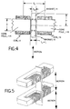
- FIG. 4 is a fragmentary sectional view of the gap region of the transducer of FIG. 1;
- FIG. 5 is a perspective view of another embodiment of the invention comprising two parallel C-core transducers with the cores in parallel spaced alignment;
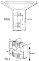
- FIG. 6 is an axial sectional view of a loudspeaker driver including the transducer of FIG. 5;
- FIG. 7 is a perspective view of another embodiment of the invention comprising a pair of U-shaped cores strapped together to define a pair of spaced gaps formed between leg ends;
- FIG. 8 is a sectional view of a loudspeaker driver incorporating the transducer of FIG. 7;
- FIG. 9 is a perspective view of another embodiment of the invention comprising a pair of U-shaped cores strapped together defining spaced gaps with a pair of spaced parallel permanent magnet members in respective gaps in fixed relationship;
- FIG. 10 is an axial sectional view of a loudspeaker driver incorporating the transducer of FIG. 9;
- FIG. 11 is a perspective view of another embodiment of the invention using a figure-of-eight core with a gap in the central bar;
- FIG. 12 is an axial sectional view of a loudspeaker driver using the transducer of FIG. 11;
- FIG. 13 is the equivalent circuit of a prior art device;
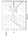
- FIG. 14 is a graphical representation of typical frequency responses for loudspeaker drivers according to the invention;
- FIG. 15 is a combined block-schematic circuit diagram of a system according to the invention incorporating the transducer according to the invention;
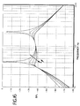
- FIG. 16 is a graphical representation of frequency responses available from the system of FIG. 15 showing the effect of varying K B ;
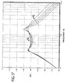
- FIG. 17 is a graphical representation of frequency responses showing the effect of changing the parameter K m ;
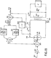
- FIG. 18 is a combined block-schematic circuit diagram of another system according to the invention;
- FIG. 19 is a combined block-schematic circuit diagram of still another system according to the invention;
- FIG. 20 is a schematic representation of a simplified electromechanical model of a transducer according to the invention; and
- FIG. 21 shows a transducer according to the invention helpful in analysis.
- With reference now to the drawings and more particularly FIG. 1 thereof, there is shown a perspective view of a transducer according to the invention. A C-
shaped core 11 of material of low magnetic reluctance, such as soft iron, carries a first winding 12 and second winding 13 of conducting material wound onlegs gap 14 substantially filled bypermanent magnets movable magnet support 17.Permanent magnets relative motion 18, between opposed surfaces ofcore 11, when the current throughwindings - Referring to FIG. 2, there is shown an axial sectional view of a loudspeaker driver incorporating the transducer of FIG. 1. The same reference symbols identify corresponding elements throughout the drawing.
- Loudspeaker
basket 21, which may be metal, plastic or other suitable material, anchors the edge of loudspeaker cone ordiaphragm 22, tospider suspension elements core 11 seated in a wall ofbasket 21 as shown. One end ofpermanent magnet support 17 is connected tospider suspension element 24 and the other end tospider suspension element 23 and cone ordiaphragm 22. The rectangular magnet assembly comprisespermanent magnet support 17 andrectangular magnets gap 14 of C-shaped core 11.Coils coils arrow 18 transverse to the plane of C-shaped core 11. The resulting force is linearly related to the current applied tocoils boundary 19 between regions of magnet polarity reaches the edge of C-shaped core 11. - Referring to FIG. 3, there is shown an idealized electrical circuit equivalent model of the transducer of FIGS. 1 and 2. This model comprises
transformer 30,resistance 31,inductance 32 andcapacitance 33.Inductance 32 andcapacitance 33 may be regarded as elements which limit the bandwidth of the transducer. - It can be shown that the maximum bandwidth for the transducer of FIG. 1 is:

where ω B is the maximum bandwidth, B m is the remanence or residual induction produced bypermanent magnets permanent magnets magnets assembly comprising magnets support 17 and C-shaped core 11 are infinitesimal, there is no magnetic leakage and the mass of the permanent magnet assembly is solely composed of the tworectangular magnet regions - The minimum mass of the moving
magnets 
where f max is the maximum force produced by thepermanent magnet assembly 17, and H m is the maximum magnetic field in the volume ofpermanent magnets magnets - Referring to FIG. 4, there is shown a fragmentary view of
gap 14 incore 11. The magnet thickness is defined as t m . The total width ofgap 14 in C-shaped core 11 is t m + t a where t a is the width of the space between C-shaped core 11 andmagnets coils inductor 32 is dependent on magnet volume and, therefore, on the mechanical work. Maximum inductive energy storage ininductor 32 occurs at maximum force:
where V m is the volume ofmagnets - To maximize the bandwidth of the transducer, this inductive stored energy should be held to a minimum. This result may be accomplished by minimizing the air gap width t a . The air gap width may be minimized by using precise suspension elements, such as 23 and 24, to maintain the permanent magnet assembly centered under all operating and environmental conditions. In applications such as a loudspeaker driver, the suspension system must not exhibit static friction because such friction is nonlinear, producing audible distortion. By locating
suspension elements core 11. These transverse forces are termed "crashing forces." Crashing forces are zero if the transducer is assembled with the magnet assembly perfectly centered ingap 14 of C-shapedcore 11. However, in practical assemblies with imperfect centering, crashing forces exist. Furthermore, the crashing forces increase in proportion to the extent of deviation from perfect centering. In effect, magnetic forces produce a negative spring characteristic which produces a force directed toward the nearer pole faceadjacent gap 14. In experimental structures, this negative spring force has been measured to be 250,000 N/m. Since the offset from perfect centering may only be 0.0001m, the absolute force is small, typically about 25 N. It is preferred that the suspension be capable of maintaining centering within 0.05 mm with a sustained load of 12.5 N for the duration of the life of the transducer. - It has also been discovered that the spacing tc between coil centers is important for minimizing inductance. In experimental transducers, it has been discovered that the inductance can be increased by more than a factor of 2 if the coil spacing is not minimized. Thus, coils 12 and 13 are positioned as close to
gap 14 as practical and may comprise multiple layer windings to further minimize tc and the resultant inductance for a given number of turns while maintaining a desired resistance. - Another feature of the invention for loudspeaker driver applications is that the structure may be used for combining stereophonic quad or other multiple-channel input signals to function as an analog and produce a monophonic excitation desirable in a system using the transducer as a subwoofer by applying, for example, the left channel signal to
coil 12 and the right channel signal tocoil 13. The resulting force produced by the transducer is then proportional to the sum of the left channel and right channel signals. - Referring to FIG. 5, there is shown a perspective view of another embodiment of the invention using two of the transducers of FIG. 1 in tandem to produce increased force. FIG. 6 shows an axial sectional view of a loudspeaker driver incorporating the transducer of FIG. 5.
- Referring to FIG. 7, there is shown a perspective view of another embodiment of the invention using
U-shaped cores 11′ and 11˝ joined together by rigid members, such as 716, on both sides. FIG. 8 is an axial sectional view of a loudspeaker driver incorporating the transducer of FIG. 7. - Referring to FIG. 9, there is shown a perspective view of another embodiment of the invention using
U-shaped cores 11′ and 11˝ held together by rigid members 41′ with the permanent magnet assemblies in spaced parallel relationship carried bysupport 17′. FIG. 10 is an axial sectional view of a loudspeaker driver incorporating the transducer of FIG. 9. - Referring to FIG. 11, there is shown a perspective view of an embodiment of the invention using a figure-of-eight
core 11˝ with the gap in thecentral cross member 11˝′C. FIG. 12 is an axial sectional view of a loudspeaker driver incorporating the transducer of FIG. 11. - Other features of the invention reside in novel applications of active feedback and switching amplifiers. It is desirable to have a loudspeaker motor as efficient as possible to reduce thermal energy loss. Achieving this feature typically interferes with obtaining a flat frequency response over the desired bandwidth for the driver. Over a wide frequency band the enclosure housing the driver presents a varying mechanical load to the loudspeaker motor. It is desired to drive this varying mechanical load with the loudspeaker motor while maintaining the resulting frequency response relatively smooth.
- The typical prior art approach chooses loudspeaker motor parameters for smooth acoustic response over the desired bandwidth. These parameters typically result in loudspeaker motors that experience high thermal stress which impose limitations on the acoustic performance of the loudspeaker enclosure system. It has been discovered that with active feedback a desired acoustic response (system alignment) can be achieved without compromising the loudspeaker motor parameters.
- Referring to FIG. 13, there is shown an idealized electrical model of a prior art speaker and its drive. An electrical audio signal on
input 101 to be reproduced energizesamplifier 102 to provide an amplified audio signal that is applied to theinput terminals 115 of the transducer. Current flows through the electrical resistance 103 andinductance 104 of the loudspeaker motor and is coupled to the mechanical motion of the cone throughtransformer 105. The moving mass of the loudspeaker motor is modeled ascapacitor 106 and the coupling from the cone to theenclosure 108 is performed through cone area transformer 107. It is convenient to combine the load modelingacoustic enclosure 108 with cone area transformer 107 to form an equivalent impedance Z′ 114.
where Z is the impedance presented byacoustic enclosure 108 and A s is the effective cone or diaphragm area. For a given acoustic enclosure and cone area characterized by an equivalent impedance Z′ 114, the parameters ∂λ/∂x, M s , L and R are chosen so that a desired frequency response occurs over the selected frequency band. The function that relates input voltage v to output volume velocity V is:
where L is the electrical inductance, R is the electrical resistance, M s is the total moving mass of the loudspeaker, s is jω where ω is 2π times the frequency, ∂λ/∂x is the force coefficient and G is the gain. This equation completely describes the effects of the motor parameters on the response of the system because the acoustic load Z′ 114 is independent of the loudspeaker motor. - The efficiency β of a loudspeaker motor is expressed as the ratio of mechanical force production to the thermal loss incurred while producing that force.

- where i is the current through
inductor 104, ∂λ/∂x is theforce coupling coefficient 105 and R is the electrical resistance 103. For thermal considerations it is desirable to make β as large as possible; however, if equation (5) is modified to substitute β for the ratio in equation (6):
the resultant equation shows that the efficiency β of the loudspeaker motor affects the loudspeaker acoustic response. - The prior art approach for achieving a relatively smooth frequency response over a specified bandwidth is to select a value for β below optimum efficiency.
- Referring to FIG. 14, there is shown a graphical representation of typical frequency responses for the equivalent circuit model of FIG. 13 for three different values of β. For low values of β the response has sharp peaks which result in a less than ideal response. As the loudspeaker motor parameter β is increased, the smoothness of response increases; however, if β is increased further to values of higher efficiency, the response smoothness decreases. The intermediate compromise value of β results in low efficiency for converting input energy into acoustic energy and increased heating of the loudspeaker motor.
- A linear power amplifier could be used with a high β motor. In such a case equalization could be used to improve the frequency response. Some power dissipation is moved from the loudspeaker to the amplifier and the equalized frequency response is sensitive to changes in loudspeaker parameters.
- According to a feature of the invention, driving the motor with a switched mode power amplifier, such as disclosed in U.S. Patent Nos. 3,294,981 and 4, 456,872, incorporated herein by reference, and using active feedback allows the use of high β motors while maintaining the desired system acoustic performance.
- Referring to FIG. 15, there is shown an electrical circuit model of an active acoustic system according to this invention. An input signal on
input 201 energizesamplifier 202 that energizes one input ofcombiner 203. The output ofcombiner 203 online 215 energizes controlled current source 204. Using current source 204 removes the effect of resistance 216 and inductance 217 on the acoustic system performance. The other input ofcombiner 203 receivesvelocity feedback 209 and acceleration feedback 210 selected to establish a desired acoustic response. The transfer function frominput line 201 to the secondary winding 214 output oftransformer 205 is:
where M′ s is the total moving mass of the loudspeaker, Ki is the voltage to current gain, K m is the acceleration feedback gain, K β is the velocity feedback gain and K is the voltage gain. For the prior art modeled in FIG. 13 with zero inductance, the transfer function frominput 101 to impedance Z′ 114 is :
- Given the same loudspeaker motor as in the prior art and a voltage to current gain K i for current amplifier 204 with:

the transfer function equation (8) becomes exactly the same as equation (9). This relationship means that the same acoustic response achieved by the prior art system of FIG. 13 is realized by the active system according to the invention of FIG. 15. Comparing equations (9) and (8) reveals that the term from equation (8)
is equivalent to β in equation (9) as to the effect on the system acoustic response. The real efficiency of the active system, however, is still
which can be made very large by reducing the electrical resistance R without affecting the desired response. This result means that equation (13) is the effective system β of the active system according to the invention:
A similar condition holds for the movingmass 206 of mass M′ s of the loudspeaker motor in the active system. This results in
as the effective system moving mass while the real moving mass is:
- Each of these parameters β effective and M s effective may be independently synthesized by the appropriate selections of K β and K m . Referring to FIG. 16, there is shown a graphical representation of frequency response for illustrating the effect of K β on the system acoustic response. If K β is small, the response has sharp peaks. As K β is increased, the response approaches the desired flat response. An unobvious aspect of the invention is that while β effective (apparent efficiency) is determined by K β , the real β (true loudspeaker motor efficiency) does not change and may be made to be very high by keeping the electrical resistance R low. If the electrical resistance R is low, then thermal losses are also low; hence, the active system according to the invention may be made considerably more efficient in converting electrical energy into acoustic energy while still providing a desired smooth frequency response in the selected bandwidth.
- Referring to FIG. 17, there is shown a graphical representation of frequency responses illustrating the effect K m has on the acoustic response for a loudspeaker motor with a large real moving mass. As K m increases the system behaves as if it has an effective moving mass that is smaller and therefore capable of achieving a higher upper half-power frequency to produce an extended frequency range at the upper end of the band. For reasons of stability it is preferred that the effective moving mass always remain positive.
- Referring to FIG. 18, there is shown another embodiment of an active system according to the invention to produce β effective and M s effective that extracts a signal proportional to the velocity v s across secondary 320 from the back voltage measured with a sense coil 323 on the motor core. Sense coil 323 measures the change in the flux in the motor core, which is a function of inductive energy stored in
inductor 315 and motor velocity v s across secondary 320. The component of the sensed voltage on line 323 that is dependent on the voltage acrossinductance 315 is removed by subtracting a signal that is proportional to the time derivative of the current throughinductor 315 provided bydifferentiator 309. The velocity v s across secondary winding 320 of the loudspeaker motor is thus available at the output ofcombiner 310 online 319 scaled by the force coefficient ∂λ/∂x corresponding to the turns ratio oftransformer 305.Networks input 301 to the output across secondary 320 for this system is exactly the same as equation (8). - The embodiments of FIGS. 15 and 18 assume voltage-controlled current sources 204 and 304, respectively. It is advantageous to use a current-controlled switching power amplifier to implement the voltage-controlled current source to negate the effect of the inductive component for the loudspeaker motor. The switching power amplifier may switch between two voltage states with one state more positive than the desired average output voltage and a second state more negative than the desired average output voltage. Another approach is to provide three voltage states: two states as described above and a third state approximately equal to zero. Such an approach is described in U.S. Patent No. 4,020,361. Both the two-state and three-state approaches are very efficient in the conversion of electrical energy into useful output. If the
electrical resistance 216 and 314 are kept small, β real is large, and the use of a switching amplifier results in an exceptionally efficient system for the reproduction of sound. This combination of loudspeaker driver and electrical driving system with active feedback results in an acoustic system producing the desired frequency response while remaining very efficient. - Referring to FIG. 19, there is shown another embodiment of the invention using a voltage-controlled voltage source. In this embodiment the effect of
inductance 410 of the loudspeaker motor on the response of the acoustic system is removed by feeding back a signal proportional to the derivative of motor current throughdifferentiator network electrical resistance 409 is kept small so as to reduce the thermal losses in the loudspeaker motor. By addingfeedback network 417 with gain K R , the effect of the reduction ofresistance 409 on acoustic response is countered. The transfer function between the input online 401 to the output across secondary 414 assumingis large is:

The term from equation (18)
is the effective inductance of the acoustic system. This property enables synthesizing the effective inductance by the appropriate choice of the gain K L fordifferentiator network 418. The other feedback term from equation (18):
is the inverse of the effective β for the system. For low values of electrical resistance R, and resultant low thermal loss, adjusting the value of K R forfeedback network 417 allows establishing a desired frequency response for the acoustic system. This result is equivalent to synthesizing an effective β while maintaining a real β that is large. This arrangement allows the use of a high inductance and high β loudspeaker motor while maintaining a desired system frequency response. A switching amplifier may also be used in this system. - Voltage-controlled voltage source 406 and
integrator 404 model the system behavior of a voltage-controlled switching amplifier. The voltage may be applied as a three-state or two-state switching amplifier as described above. The switching amplifier may be very efficient in the conversion of electrical energy so that combined with a high β loudspeaker motor and feedback system according to the invention, the overall sound reproduction system is exceptionally efficient. - Referring to FIG. 20, there is shown a schematic representation of a simplified electromechanical model of a transducer according to the invention.
Element R 2001 represents the electrical resistance ofcoils L 2002 the inductance ofcoils M 2004 the moving mass of the transducer. This model is helpful in determining the bandwidth of the transducer. - The characteristic equation of this model is:
and solving this quadratic equation yields the critical values (poles) of the electromechanical system.
It is convenient to define the frequency bandwidth as the geometric mean of s 1 and s 2 .
The equation defines the upper limit for the frequency bandwidth of the transducer under ideal conditions. - Referring to FIG. 21, there is shown a transducer helpful in determining minimum inductance L min and mass M min under ideal conditions.


where N is number of turns - ω
- is angular frequency, radians/second
- h
- is height of magnet, meters
- µm
- is Linear permeability of magnet material, Henries/meter
- tm
- is thickness of magnet, meters
- and dm
- is density of magnet material, Kg/m3
- A speaker transducer produces a maximum volume displacement V max , over a desired bandwidth for a given maximum sound pressure level (loudness). This maximum volume displacement is expressed as the peak-to-peak excursion of the motor times the effective area of the speaker diaphragm. For the transducer according to the invention:

where A s is the effective area of the speaker diaphragm. Since for a given speaker and enclosure combination the maximum volume displace V max is constant, equation 28 can be expressed to account for this constraint.
This equation reveals that if the speaker transducer is expected to produce a fixed V max , then increasing the cone area increases the bandwidth. This property is also true of prior art moving coil speaker motors, however, for a moving coil speaker to take advantage of this result the magnet structure would be prohibitively large for high sound pressure level (SPL) bass reproduction. The speaker transducer according to the invention, on the other hand, can take advantage of this result while being practical to realize. - Other embodiments are within the claims.

under ideal conditions. Substituting these parameters inequation 24 yields the maximum frequency bandwidth (radians per second), B.W. max , for the transducer of FIG. 21 under ideal conditions:
Claims (28)
- A transducer comprising,
a core of low reluctance magnetic material formed with a gap,
at least one coil wound on said core adjacent to said gap,
and a permanent magnet assembly in and substantially filling said air gap in noncontacting relationship with said core and supported to allow relative movement between said permanent magnet assembly and said core. - A transducer in accordance with claim 1 wherein said core is generally C-shaped.
- A transducer in accordance with claim 1 wherein said core is substantially 8-shaped.
- A transducer in accordance with claim 1 wherein said core is substantially U-shaped.
- A transducer in accordance with claim 1 and further comprising a frame having first and second ends,
a first suspension element at said second end,
a second suspension element,
said permanent magnet assembly being connected between said first and second suspension elements. - A transducer in accordance with claim 5 wherein said first and second suspension elements and said permanent magnet assembly are mounted to said frame.
- A transducer in accordance with claim 1 wherein said permanent magnet comprises first and second contiguous permanent magnet elements having adjacent unlike poles along a boundary substantially midway between opposed surfaces of said core along the direction of said relative motion .
- A transducer in accordance with claim 1 and further comprising a loudspeaker diaphragm connected to said permanent magnet assembly.
- A transducer is accordance with claim 5 and further comprising,
a loudspeaker diaphragm connected to said permanent magnet,
said first and second suspension elements being spiders. - A transducer in accordance with claim 1 and further comprising,
a combiner having a signal input, a feedback input and an output for providing a combined signal on the combiner output related to the combination of the signals on said signal input and said feedback input,
a controlled signal source having an input coupled to said combiner output and a signal output providing a controlled signal related to the signal on the controlled signal source input,
said controlled signal source output being connected to said at least one coil,
and a feedback circuit intercoupling said transducer and said combiner feedback input. - The apparatus of claim 10 wherein said feedback circuit provides a feedback signal related to at least one of velocity and acceleration of said permanent magnet assembly.
- The apparatus of claim 11 wherein said feedback circuit comprises,
a source of a velocity signal related to said velocity,
a differentiator for providing a derivative signal proportional to the time derivative of the signal provided by said controlled signal source,
an input combiner having a derivative input for receiving said derivative signal and a velocity input for receiving said velocity signal and an output for providing a scaled velocity signal related to the combination of signals on said velocity and derivative inputs,
an effective Beta network having an input coupled to said input combiner output and an output for providing an effective Beta signal,
an effective moving mass network having an input coupled to said input combiner output and an output for providing an effective moving mass signal, and
an output combiner having an effective Beta input coupled to the effective Beta network output, an effective moving mass input coupled to the effective moving mass network output and an output for providing a signal related to the signals on said effective Beta input and said effective moving mass input and coupled to said combiner feedback input. - The apparatus of claim 10 wherein said controlled signal source is a controlled voltage source.
- The apparatus of claim 10 wherein said controlled signal source is a controlled current source.
- The apparatus of claim 10 wherein said controlled signal source is a switching amplifier.
- The apparatus of claim 10 wherein said controlled signal source is a linear amplifier.
- The apparatus of claim 15 wherein said controlled signal source is a current-controlled multi-state modulation amplifier.
- The apparatus of claim 15 wherein said controlled source is a voltage-controlled multi-state modulation amplifier.
- A transducer in accordance with claim 1 wherein there are first and second coils wound on said core adjacent to and on opposite sides of said gap.
- The apparatus of claim 16 and further comprising,
equalizer circuitry coacting with said transducer for reducing nonuniformity in frequency response of said transducer within the operating frequency range thereof. - The apparatus of claim 13 wherein said feedback circuit comprises,
a differentiator network intercoupling said transducer and said combiner arranged to provide a feedback signal proportional to the current in said at least one coil,
and a resistance sensitive network intercoupling said transducer and said combiner arranged to provide a feedback signal that reduces the effect of the resistance of said at least one coil. - The transducer of claim 1 wherein the operating frequency range of said transducer is in the bass frequency range with a bandwidth of the order of √(1/LM(∂λ/∂x)⁻²), where L is the coil inductance, M is the transducer moving mass and δλ/∂x is the electromechanical coupling between coil inductance and moving mass.
- A transducer in accordance with claim 8 and further comprising,
first and second suspension elements respectively connected to opposite ends of said permanent magnet assembly,
the combined mass of said loudspeaker diaphragm and said suspension elements being less than twice the mass of said permanent magnet assembly,
said transducer having coil inductance with at least one-third of said coil inductance being attributable to magnetic energy stored in said gap. - A transducer in accordance with claim 8 wherein the mass of said permanent magnet assembly is at least 10 grams.
- A transducer in accordance with claim 24 wherein the area of said diaphragm is greater than or equal to 0.015 m2.
- A transducer in accordance with claim 1 and further comprising,
an amplifier connected to said at least one coil,
said amplifier having an output impedance characterized by at least one of positive resistance and negative inductance,
said positive resistance being at least 1/5 the resistance of said at least one coil. - Apparatus in accordance with claim 26 wherein said amplifier is a switching amplifier.
- Apparatus in accordance with claim 26 wherein said negative inductance magnitude is at least 1/2 the inductance of said at least one coil.
Applications Claiming Priority (2)
| Application Number | Priority Date | Filing Date | Title |
|---|---|---|---|
| US667461 | 1991-03-11 | ||
| US07/667,461 US5216723A (en) | 1991-03-11 | 1991-03-11 | Permanent magnet transducing |
Publications (3)
| Publication Number | Publication Date |
|---|---|
| EP0508570A2 true EP0508570A2 (en) | 1992-10-14 |
| EP0508570A3 EP0508570A3 (en) | 1993-08-04 |
| EP0508570B1 EP0508570B1 (en) | 1995-12-20 |
Family
ID=24678317
Family Applications (1)
| Application Number | Title | Priority Date | Filing Date |
|---|---|---|---|
| EP92301397A Expired - Lifetime EP0508570B1 (en) | 1991-03-11 | 1992-02-20 | Permanent magnet transducer |
Country Status (6)
| Country | Link |
|---|---|
| US (1) | US5216723A (en) |
| EP (1) | EP0508570B1 (en) |
| JP (1) | JPH0591592A (en) |
| AT (1) | ATE131991T1 (en) |
| CA (1) | CA2061444A1 (en) |
| DE (1) | DE69206863T2 (en) |
Cited By (6)
| Publication number | Priority date | Publication date | Assignee | Title |
|---|---|---|---|---|
| WO2011123265A1 (en) * | 2010-03-31 | 2011-10-06 | Bose Corporation | Moving magnet levered loudspeaker |
| US8295537B2 (en) | 2010-03-31 | 2012-10-23 | Bose Corporation | Loudspeaker moment and torque balancing |
| US9055370B2 (en) | 2012-08-31 | 2015-06-09 | Bose Corporation | Vibration-reducing passive radiators |
| WO2021150278A1 (en) * | 2020-01-21 | 2021-07-29 | Clean Energy Labs, Llc | Electroacoustic drivers and loudspeakers containing same |
| IT202100032897A1 (en) | 2021-12-29 | 2023-06-29 | Powersoft S P A | TRANSDUCER FOR A SOUND SPEAKER AND METHOD FOR PRODUCING THE TRANSDUCER. |
| EP4207809A1 (en) | 2021-12-29 | 2023-07-05 | Powersoft SpA | Sound diffuser and a method for diffusing a sound through a sound diffuser |
Families Citing this family (35)
| Publication number | Priority date | Publication date | Assignee | Title |
|---|---|---|---|---|
| US5991423A (en) * | 1998-09-21 | 1999-11-23 | Lucent Technologies Inc. | Planar magnetic continuous-tone transducer |
| US6405599B1 (en) * | 2000-01-13 | 2002-06-18 | Bose Corporation | Frictionless motor material testing |
| US7238165B2 (en) * | 2002-02-21 | 2007-07-03 | Design Mentor, Inc. | Fluid pump |
| US6945541B2 (en) * | 2003-01-21 | 2005-09-20 | Bose Corporation | Vehicle suspension |
| US6926288B2 (en) * | 2003-06-02 | 2005-08-09 | Bose Corporation | Electromagnetic interference filter |
| US7219684B2 (en) * | 2005-01-28 | 2007-05-22 | Rain Bird Corporation | Saddle tee and tool for irrigation lines |
| US8224009B2 (en) * | 2007-03-02 | 2012-07-17 | Bose Corporation | Audio system with synthesized positive impedance |
| US7726193B2 (en) * | 2007-09-27 | 2010-06-01 | Baker Hughes Incorporated | Electromagnetic acoustic transducer with cross-talk elimination |
| DE102009052129A1 (en) | 2009-11-05 | 2011-05-12 | Technische Universität Dresden | Electromechanical transducer for use as e.g. loudspeaker, has rotor with permanent magnets, where side surfaces of permanent magnets in associated air gaps are moved within movement area and do not move out of area |
| US8610318B2 (en) * | 2011-03-29 | 2013-12-17 | Bose Corporation | Moving magnet actuator magnet carrier |
| US20120248898A1 (en) * | 2011-03-29 | 2012-10-04 | Richard Tucker Carlmark | Moving Magnet Actuator Magnet Carrier |
| US20120280579A1 (en) * | 2011-05-06 | 2012-11-08 | Bose Corporation | Linear moving magnet motor cogging force ripple reducing |
| US9606035B2 (en) | 2011-12-21 | 2017-03-28 | Ta Instruments-Waters Llc | System for mechanical stimulation and characterization of biologic samples |
| US9496778B2 (en) | 2012-08-22 | 2016-11-15 | Ta Instruments-Waters L.L.C. | Electromagnetic motor |
| US10028062B2 (en) * | 2013-03-15 | 2018-07-17 | Bose Corporation | Driving plural armatures with a common stator |
| ES2908079T3 (en) * | 2013-06-14 | 2022-04-27 | Genelec Oy | Suspension element for suspending the diaphragm of a loudspeaker driver to its chassis, as well as a driver and loudspeaker comprising said element |
| DK2914018T3 (en) * | 2014-02-26 | 2017-01-30 | Sonion Nederland Bv | Speaker, luminaire and method |
| US9258648B2 (en) | 2014-03-07 | 2016-02-09 | Bose Corporation | Levered loudspeakers |
| US9601969B2 (en) | 2014-03-07 | 2017-03-21 | Bose Corporation | Inhibiting rocking of loads driven by plural levers |
| US9497549B2 (en) | 2014-03-07 | 2016-11-15 | Bose Corporation | Levered loudspeakers |
| US9357279B2 (en) | 2014-03-07 | 2016-05-31 | Bose Corporation | Elastomeric torsion bushings for levered loudspeakers |
| US9130445B1 (en) * | 2014-08-04 | 2015-09-08 | David Micah Katz | Electromechanical transducer with non-circular voice coil |
| CN204733374U (en) * | 2015-06-23 | 2015-10-28 | 瑞声光电科技(常州)有限公司 | Loud speaker |
| CN204741558U (en) * | 2015-06-23 | 2015-11-04 | 瑞声光电科技(常州)有限公司 | Loudspeaker |
| US10154347B2 (en) | 2015-10-23 | 2018-12-11 | Bose Corporation | Bushings constrained by compression in levered apparatus |
| US11040682B1 (en) | 2016-03-21 | 2021-06-22 | Paradigm Research and Engineering, LLC | Blast detection and safety deployment system and method for using the same |
| TWI610576B (en) * | 2016-08-15 | 2018-01-01 | 緯創資通股份有限公司 | Loudspeaker |
| US10084410B2 (en) * | 2016-12-15 | 2018-09-25 | Bose Corporation | Moving magnet motor and transducer with moving magnet motor |
| US11778385B2 (en) * | 2017-06-23 | 2023-10-03 | Cochlear Limited | Electromagnetic transducer with non-axial air gap |
| CN109803216B (en) * | 2019-01-15 | 2020-11-20 | 哈尔滨工程大学 | A moving magnet linear actuator |
| PH22020050740U3 (en) | 2019-12-30 | 2023-07-26 | Knowles Electronics Llc | Acoustic receiver with coils and a terminal board |
| US11600435B2 (en) | 2020-12-31 | 2023-03-07 | Knowles Electronics, Llc | Coil bobbin for a balanced armature receiver |
| US11889284B2 (en) * | 2021-03-25 | 2024-01-30 | Sound Solutions International Co., Ltd. | Multi magnet electrodynamic acoustic transducer and electroacoustic system |
| EP4374582A1 (en) * | 2021-07-19 | 2024-05-29 | Brane Audio, LLC | Electroacoustic drivers and loudspeakers containing same |
| US12306018B1 (en) | 2022-11-22 | 2025-05-20 | St3 Development Corporation | Material testing apparatus having vibration mitigation |
Family Cites Families (8)
| Publication number | Priority date | Publication date | Assignee | Title |
|---|---|---|---|---|
| US2026994A (en) * | 1929-05-15 | 1936-01-07 | Messick Charles | Armature for magnetic movements |
| US3062926A (en) * | 1959-03-20 | 1962-11-06 | John J Ronci | Magnet with vibratable armature |
| US3937904A (en) * | 1974-08-07 | 1976-02-10 | Hitachi Magnetics Corporation | Moving magnet electroacoustic transducer |
| US4020361A (en) * | 1974-10-04 | 1977-04-26 | Delta Electronic Control Corporation | Switching mode power controller of large dynamic range |
| DE3313333A1 (en) * | 1983-04-13 | 1984-10-18 | Battelle-Institut E.V., 6000 Frankfurt | Device for producing magnetic forces |
| GB2149272B (en) * | 1983-10-26 | 1987-06-17 | Adam Kovacs | Electromechanical transducer |
| DE3527501A1 (en) * | 1984-09-03 | 1986-03-13 | Sanden Corp., Isesaki, Gunma | DYNAMIC CONVERTER DEVICE |
| US5009281A (en) * | 1988-03-10 | 1991-04-23 | Yamaha Corporation | Acoustic apparatus |
-
1991
- 1991-03-11 US US07/667,461 patent/US5216723A/en not_active Expired - Lifetime
-
1992
- 1992-02-18 CA CA002061444A patent/CA2061444A1/en not_active Abandoned
- 1992-02-20 AT AT92301397T patent/ATE131991T1/en not_active IP Right Cessation
- 1992-02-20 DE DE69206863T patent/DE69206863T2/en not_active Expired - Lifetime
- 1992-02-20 EP EP92301397A patent/EP0508570B1/en not_active Expired - Lifetime
- 1992-03-06 JP JP4050013A patent/JPH0591592A/en active Pending
Cited By (16)
| Publication number | Priority date | Publication date | Assignee | Title |
|---|---|---|---|---|
| WO2011123265A1 (en) * | 2010-03-31 | 2011-10-06 | Bose Corporation | Moving magnet levered loudspeaker |
| US8295536B2 (en) | 2010-03-31 | 2012-10-23 | Bose Corporation | Moving magnet levered loudspeaker |
| US8295537B2 (en) | 2010-03-31 | 2012-10-23 | Bose Corporation | Loudspeaker moment and torque balancing |
| US9055370B2 (en) | 2012-08-31 | 2015-06-09 | Bose Corporation | Vibration-reducing passive radiators |
| US12003940B2 (en) | 2020-01-21 | 2024-06-04 | Brane Audio, LLC | Electroacoustic drivers and loudspeakers containing same |
| US12003941B2 (en) | 2020-01-21 | 2024-06-04 | Brane Audio, LLC | Electroacoustic drivers and loudspeakers containing same |
| WO2021150278A1 (en) * | 2020-01-21 | 2021-07-29 | Clean Energy Labs, Llc | Electroacoustic drivers and loudspeakers containing same |
| US12003943B2 (en) | 2020-01-21 | 2024-06-04 | Brane Audio, LLC | Electroacoustic drivers and loudspeakers containing same |
| US12003942B2 (en) | 2020-01-21 | 2024-06-04 | Brane Audio, LLC | Electroacoustic drivers and loudspeakers containing same |
| US12126979B2 (en) | 2020-01-21 | 2024-10-22 | Brane Audio, LLC | Electroacoustic drivers and loudspeakers containing same |
| US12256207B2 (en) | 2020-01-21 | 2025-03-18 | Brane Audio, LLC | Electroacoustic drivers and loudspeakers containing same |
| US12284507B2 (en) | 2020-01-21 | 2025-04-22 | Brane Audio, LLC | Force transducers for electroacoustic drivers and loudspeakers containing same |
| IT202100032897A1 (en) | 2021-12-29 | 2023-06-29 | Powersoft S P A | TRANSDUCER FOR A SOUND SPEAKER AND METHOD FOR PRODUCING THE TRANSDUCER. |
| EP4207809A1 (en) | 2021-12-29 | 2023-07-05 | Powersoft SpA | Sound diffuser and a method for diffusing a sound through a sound diffuser |
| EP4539503A2 (en) | 2021-12-29 | 2025-04-16 | Powersoft SpA | Sound diffuser and a method for diffusing a sound through a sound diffuser |
| US12309566B2 (en) | 2021-12-29 | 2025-05-20 | Powersoft S.P.A. | Sound diffuser and a method for diffusing a sound through a sound diffuser |
Also Published As
| Publication number | Publication date |
|---|---|
| DE69206863D1 (en) | 1996-02-01 |
| EP0508570B1 (en) | 1995-12-20 |
| ATE131991T1 (en) | 1996-01-15 |
| CA2061444A1 (en) | 1992-09-12 |
| JPH0591592A (en) | 1993-04-09 |
| DE69206863T2 (en) | 1996-05-15 |
| US5216723A (en) | 1993-06-01 |
| EP0508570A3 (en) | 1993-08-04 |
Similar Documents
| Publication | Publication Date | Title |
|---|---|---|
| EP0508570B1 (en) | Permanent magnet transducer | |
| US8385583B2 (en) | Methods and apparatus for reduced distortion balanced armature devices | |
| EP0799520B1 (en) | Electromagnetic force generator | |
| US6917690B2 (en) | Electromagnetic transducer having multiple magnetic air gaps whose magnetic flux is in a same direction | |
| JP3192372B2 (en) | Thin electromagnetic transducer | |
| US4273968A (en) | Electroacoustic transducer with magnetic flux directed slantly across a diaphragm | |
| EP0548579B1 (en) | Balanced armature transducers with transverse gap | |
| US7039213B2 (en) | Speaker driver | |
| AU2009242055B2 (en) | Ironless and leakage free coil transducer motor assembly | |
| US7873180B2 (en) | Voice coil actuator | |
| JP2009278523A (en) | Speaker | |
| JP2022161138A (en) | voice coil motor | |
| KR20060014662A (en) | Voice coil structure of speaker | |
| US20020080991A1 (en) | Universal ribbon element-module for two or more membrane-widths with optimized flow and drive | |
| JP3458922B2 (en) | Voice coil type linear motor | |
| JP3961960B2 (en) | Speaker | |
| JP2001186589A (en) | Speaker unit | |
| Leung et al. | An application of linear motor to loudspeaker systems | |
| JPH0759195A (en) | Speaker | |
| JPS6119600Y2 (en) | ||
| KR800000764B1 (en) | Motorized Pickup | |
| Merit et al. | An ironless low frequency subwoofer functioning under its resonance frequency. | |
| JPS60196099A (en) | electromagnetic driver | |
| KR20200091602A (en) | Speaker | |
| JPH11341594A (en) | Speaker |
Legal Events
| Date | Code | Title | Description |
|---|---|---|---|
| PUAI | Public reference made under article 153(3) epc to a published international application that has entered the european phase |
Free format text: ORIGINAL CODE: 0009012 |
|
| AK | Designated contracting states |
Kind code of ref document: A2 Designated state(s): AT BE CH DE DK ES FR GB GR IT LI LU NL PT SE |
|
| PUAL | Search report despatched |
Free format text: ORIGINAL CODE: 0009013 |
|
| AK | Designated contracting states |
Kind code of ref document: A3 Designated state(s): AT BE CH DE DK ES FR GB GR IT LI LU NL PT SE |
|
| 17P | Request for examination filed |
Effective date: 19940201 |
|
| 17Q | First examination report despatched |
Effective date: 19940620 |
|
| GRAA | (expected) grant |
Free format text: ORIGINAL CODE: 0009210 |
|
| AK | Designated contracting states |
Kind code of ref document: B1 Designated state(s): AT BE CH DE DK ES FR GB GR IT LI LU NL PT SE |
|
| PG25 | Lapsed in a contracting state [announced via postgrant information from national office to epo] |
Ref country code: IT Free format text: LAPSE BECAUSE OF FAILURE TO SUBMIT A TRANSLATION OF THE DESCRIPTION OR TO PAY THE FEE WITHIN THE PRE;WARNING: LAPSES OF ITALIAN PATENTS WITH EFFECTIVE DATE BEFORE 2007 MAY HAVE OCCURRED AT ANY TIME BEFORE 2007. THE CORRECT EFFECTIVE DATE MAY BE DIFFERENT FROM THE ONE RECORDED.SCRIBED TIME-LIMIT Effective date: 19951220 Ref country code: CH Free format text: LAPSE BECAUSE OF FAILURE TO SUBMIT A TRANSLATION OF THE DESCRIPTION OR TO PAY THE FEE WITHIN THE PRESCRIBED TIME-LIMIT Effective date: 19951220 Ref country code: LI Free format text: LAPSE BECAUSE OF FAILURE TO SUBMIT A TRANSLATION OF THE DESCRIPTION OR TO PAY THE FEE WITHIN THE PRESCRIBED TIME-LIMIT Effective date: 19951220 Ref country code: DK Effective date: 19951220 Ref country code: FR Effective date: 19951220 Ref country code: GR Free format text: LAPSE BECAUSE OF FAILURE TO SUBMIT A TRANSLATION OF THE DESCRIPTION OR TO PAY THE FEE WITHIN THE PRESCRIBED TIME-LIMIT Effective date: 19951220 Ref country code: ES Free format text: THE PATENT HAS BEEN ANNULLED BY A DECISION OF A NATIONAL AUTHORITY Effective date: 19951220 Ref country code: NL Free format text: LAPSE BECAUSE OF FAILURE TO SUBMIT A TRANSLATION OF THE DESCRIPTION OR TO PAY THE FEE WITHIN THE PRESCRIBED TIME-LIMIT Effective date: 19951220 Ref country code: BE Effective date: 19951220 Ref country code: AT Effective date: 19951220 |
|
| REF | Corresponds to: |
Ref document number: 131991 Country of ref document: AT Date of ref document: 19960115 Kind code of ref document: T |
|
| REF | Corresponds to: |
Ref document number: 69206863 Country of ref document: DE Date of ref document: 19960201 |
|
| PG25 | Lapsed in a contracting state [announced via postgrant information from national office to epo] |
Ref country code: LU Free format text: LAPSE BECAUSE OF NON-PAYMENT OF DUE FEES Effective date: 19960229 |
|
| PG25 | Lapsed in a contracting state [announced via postgrant information from national office to epo] |
Ref country code: SE Effective date: 19960320 Ref country code: PT Effective date: 19960320 |
|
| EN | Fr: translation not filed | ||
| NLV1 | Nl: lapsed or annulled due to failure to fulfill the requirements of art. 29p and 29m of the patents act | ||
| PLBE | No opposition filed within time limit |
Free format text: ORIGINAL CODE: 0009261 |
|
| 26N | No opposition filed | ||
| REG | Reference to a national code |
Ref country code: GB Ref legal event code: IF02 |
|
| PGFP | Annual fee paid to national office [announced via postgrant information from national office to epo] |
Ref country code: DE Payment date: 20110225 Year of fee payment: 20 |
|
| PGFP | Annual fee paid to national office [announced via postgrant information from national office to epo] |
Ref country code: GB Payment date: 20110223 Year of fee payment: 20 |
|
| REG | Reference to a national code |
Ref country code: DE Ref legal event code: R071 Ref document number: 69206863 Country of ref document: DE |
|
| REG | Reference to a national code |
Ref country code: DE Ref legal event code: R071 Ref document number: 69206863 Country of ref document: DE |
|
| REG | Reference to a national code |
Ref country code: GB Ref legal event code: PE20 Expiry date: 20120219 |
|
| PG25 | Lapsed in a contracting state [announced via postgrant information from national office to epo] |
Ref country code: DE Free format text: LAPSE BECAUSE OF EXPIRATION OF PROTECTION Effective date: 20120221 |
|
| PG25 | Lapsed in a contracting state [announced via postgrant information from national office to epo] |
Ref country code: GB Free format text: LAPSE BECAUSE OF EXPIRATION OF PROTECTION Effective date: 20120219 |