EP4539503A2 - Schalldiffusor und verfahren zur diffusion eines schalls durch einen schalldiffusor - Google Patents
Schalldiffusor und verfahren zur diffusion eines schalls durch einen schalldiffusor Download PDFInfo
- Publication number
- EP4539503A2 EP4539503A2 EP25153194.3A EP25153194A EP4539503A2 EP 4539503 A2 EP4539503 A2 EP 4539503A2 EP 25153194 A EP25153194 A EP 25153194A EP 4539503 A2 EP4539503 A2 EP 4539503A2
- Authority
- EP
- European Patent Office
- Prior art keywords
- magnet
- longitudinal axis
- radiator
- along
- coil
- Prior art date
- Legal status (The legal status is an assumption and is not a legal conclusion. Google has not performed a legal analysis and makes no representation as to the accuracy of the status listed.)
- Pending
Links
Images


Classifications
-
- H—ELECTRICITY
- H04—ELECTRIC COMMUNICATION TECHNIQUE
- H04R—LOUDSPEAKERS, MICROPHONES, GRAMOPHONE PICK-UPS OR LIKE ACOUSTIC ELECTROMECHANICAL TRANSDUCERS; DEAF-AID SETS; PUBLIC ADDRESS SYSTEMS
- H04R27/00—Public address systems
-
- H—ELECTRICITY
- H04—ELECTRIC COMMUNICATION TECHNIQUE
- H04R—LOUDSPEAKERS, MICROPHONES, GRAMOPHONE PICK-UPS OR LIKE ACOUSTIC ELECTROMECHANICAL TRANSDUCERS; DEAF-AID SETS; PUBLIC ADDRESS SYSTEMS
- H04R11/00—Transducers of moving-armature or moving-core type
- H04R11/02—Loudspeakers
-
- H—ELECTRICITY
- H04—ELECTRIC COMMUNICATION TECHNIQUE
- H04R—LOUDSPEAKERS, MICROPHONES, GRAMOPHONE PICK-UPS OR LIKE ACOUSTIC ELECTROMECHANICAL TRANSDUCERS; DEAF-AID SETS; PUBLIC ADDRESS SYSTEMS
- H04R31/00—Apparatus or processes specially adapted for the manufacture of transducers or diaphragms therefor
- H04R31/006—Interconnection of transducer parts
-
- H—ELECTRICITY
- H04—ELECTRIC COMMUNICATION TECHNIQUE
- H04R—LOUDSPEAKERS, MICROPHONES, GRAMOPHONE PICK-UPS OR LIKE ACOUSTIC ELECTROMECHANICAL TRANSDUCERS; DEAF-AID SETS; PUBLIC ADDRESS SYSTEMS
- H04R7/00—Diaphragms for electromechanical transducers; Cones
- H04R7/16—Mounting or tensioning of diaphragms or cones
- H04R7/18—Mounting or tensioning of diaphragms or cones at the periphery
-
- H—ELECTRICITY
- H04—ELECTRIC COMMUNICATION TECHNIQUE
- H04R—LOUDSPEAKERS, MICROPHONES, GRAMOPHONE PICK-UPS OR LIKE ACOUSTIC ELECTROMECHANICAL TRANSDUCERS; DEAF-AID SETS; PUBLIC ADDRESS SYSTEMS
- H04R9/00—Transducers of moving-coil, moving-strip, or moving-wire type
- H04R9/02—Details
- H04R9/04—Construction, mounting, or centering of coil
- H04R9/045—Mounting
-
- H—ELECTRICITY
- H04—ELECTRIC COMMUNICATION TECHNIQUE
- H04R—LOUDSPEAKERS, MICROPHONES, GRAMOPHONE PICK-UPS OR LIKE ACOUSTIC ELECTROMECHANICAL TRANSDUCERS; DEAF-AID SETS; PUBLIC ADDRESS SYSTEMS
- H04R9/00—Transducers of moving-coil, moving-strip, or moving-wire type
- H04R9/06—Loudspeakers
-
- H—ELECTRICITY
- H04—ELECTRIC COMMUNICATION TECHNIQUE
- H04R—LOUDSPEAKERS, MICROPHONES, GRAMOPHONE PICK-UPS OR LIKE ACOUSTIC ELECTROMECHANICAL TRANSDUCERS; DEAF-AID SETS; PUBLIC ADDRESS SYSTEMS
- H04R9/00—Transducers of moving-coil, moving-strip, or moving-wire type
- H04R9/02—Details
- H04R9/025—Magnetic circuit
Definitions
- the technical purpose of the invention is therefore to provide a sound diffuser and a method for diffusing a sound through a sound diffuser which are able to overcome the drawbacks of the prior art.
- a further aim of the invention is to provide a method diffusing a sound through a sound diffuser which is simple and efficient.
- the transducer according to the invention could also be used in the so-called bass boards.
- the transducer is suitable for use in systems for active control of noise and vibrations for helicopters and similar vehicles.
- the transducer may also be used for destructive vibration tests and/or in material testing equipment (for example, traction/compression testing machines).
- the transducer could also be used in vibrating conveyors.
- the transducer also comprises a ferromagnetic circuit including a core, provided with a central portion around which the coil is wound, and an outer lateral portion located at the side of the coil and at least partly surrounding the coil.
- the magnet has a first end and a second end.
- the magnet has a south pole and a north pole extending between the first end and the second end parallel to the longitudinal axis.
- the magnet is movable, inside the air gap, along a movement direction parallel to the longitudinal axis.
- the coil is a single coil.
- the central portion extends along the longitudinal axis.
- the inner lateral portion has a high magnetic permeability zone close to (or facing) the coil.
- the inner lateral wall also has an annular shape and defines an inner ring surrounding the coil.
- the inner ring is interposed between the coil and the magnetic ring. In this situation, the coil is entirely embedded into the ferromagnetic circuit and only faces the air gap for the part left free by the slot.
- the radial architecture of the transducer is particularly advantageous since it allows the efficiency of the transducer to be increased while keeping its dimensions compact.
- One between the magnet and the further magnet is interposed between the first rectilinear portion of the coil and the first part of the outer lateral portion whilst the other is interposed between the second rectilinear portion of the coil and the second part of the outer lateral portion.
- the first rectilinear portion and the magnet have the same axial extension as the second rectilinear portion and the further magnet have the same axial extension.
- both the magnet and the further magnet are moved, within the air gap, along the respective movement directions.
- the magnetic field generated by the magnet and by the further magnet is disturbed by the magnetic energizing field in such a way that the magnet and the further magnet move (raising and lowering) along the respective movement directions.
- This motion of the magnet and of the further magnet causes an oscillation of the radiator of the diffuser to which the transducer is operatively connected.
- the transducer comprises a supporting body operatively connected to the magnet and to the further magnet to make the movement of the magnet and the further magnet integral along the respective movement directions when the coil is energized.
- the transducer also comprises a retaining band, preferably made of metal, configured to prevent a movement of the supporting body transversely to the longitudinal axis.
- the retaining band is elastically deformable in such a way that a movement of the supporting body corresponds to a bending of the retaining band.
- the retaining band allows the movement of the magnets along the respective movement directions and, at the same time, prevents unwanted movement along different directions.
- first and second rectilinear portions may be mutually facing.
- the third and fourth rectilinear portions may be mutually facing.
- the first, second, third and fourth rectilinear portions lie on a same plane transverse to the longitudinal axis.
- the first magnet is placed between the first rectilinear portion and the first part of the outer side portion; the second magnet is placed between the second rectilinear portion and the second part; the third magnet is placed between the third rectilinear portion and the third part; the fourth magnet is placed between the fourth rectilinear portion and the fourth part.
- the first, second, third and fourth magnets are movable along respective movement directions, parallel to the longitudinal axis.
- the core is made by a sintered magnetic composite, SMC.
- the sintered magnetic composite is characterized by a high induction and high permeability; also, it reduces the losses due to parasitic currents and it reduces the material hysteresis.
- the method comprises a step of preparing a transducer comprising a coil provided with a plurality of turns each extending on a respective plane transversal to a longitudinal axis. The turns are juxtaposed along the longitudinal axis.
- the transducer also comprises a ferromagnetic circuit comprising a core provided with a central portion around which the coil is wound and an outer lateral portion located at the side of the coil and separated from the coil by an air gap.
- the transducer also comprises at least one magnetizable element.
- the method then comprises a step of magnetizing the at least one magnetizable element by activating the auxiliary magnetizing circuit in such a way as to make a permanent magnet (or if there is the further magnetizable element, a further permanent magnet).
- the present description also provides a method for diffusing a sound through a sound diffuser.
- the method comprises a step for preparing a transducer comprising a coil having a plurality of turns each extending on a respective plane transverse to a longitudinal axis, the turns being juxtaposed along the longitudinal axis.
- the transducer comprises a ferromagnetic circuit comprising a core provided with a central portion around which the coil is wound, an outer lateral portion located at the side of the coil and separated from the coil by an air gap, and at least one magnetizable element.
- the turns of the coil surround the longitudinal axis and the coil comprises a plurality of rectilinear portions transverse to the longitudinal axis, including a first, a second, a third and a fourth rectilinear portion, joined together by curved connection sections, wherein the first and second straight portions are mutually facing and the third and fourth portions are mutually facing.
- the outer lateral portion may comprise a plurality of parts surrounding the coil, cooperating with the corresponding plurality of rectilinear portions to define a plurality of air gaps, wherein the plurality of parts of the outer lateral portion comprises first, second, third and fourth part.
- the invention also relates to a sound diffuser comprising a housing.
- the diffuser may also comprise a case.
- the suspension is configured to allow the radiator to oscillate relative to the housing.
- the mass of the transducer is comparable with the mass of the sound coupling systems of the sound diffuser, it is convenient to reverse the motion of the at least one magnet relative to that of the radiator to allow the masses to be opposed in an inertial manner in such a way that the sound diffuser is balanced, minimizing the mechanical vibrations produced during the operation.
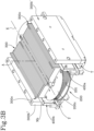
- the upper sub-portion 300c' and the lower sub-portion 300c" act in conjunction to wind around almost the entire coil 200 except the point at which the slot "I" is made.
- the slot "I" extends annularly in such a way as to define the upper sub-portion 300c' and the lower sub-portion 300c".
- the first and second parts 300b', 300b" of the outer lateral portion 300b face, respectively, the first rectilinear portion 200a and the second rectilinear portion 200b.
- the magnet 400a and the further magnet 400b have the same pole "Sa”, “Na”, “Sb”, “Nb” facing the coil 200.
- the first and second rectilinear portions 200a, 200b of the coil 200 are side by side with the central portion 300a of the ferromagnetic circuit 300 and are wrapped at the bottom and top by the upper and lower sub-parts 300c', 300c" of the inner lateral portion 300c.
- first and second rectilinear portions 200a, 200b of the coil 200 are immersed in the ferromagnetic circuit 300 substantially along their entire extension whilst the connecting portions 200c protrude from the ferromagnetic circuit 300.
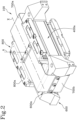
- the transducer 100 comprises a supporting body 600 operatively connected to the magnet 400 and to the further magnet 400b to make the movement of the magnet 400a and of the further magnet 400b integral along the respective movement directions "M1", “M2" when the coil 200 is energized.
- the magnet 400a and the further magnet 400b move simultaneously energized from the magnetic energizing field. Since the magnets 400a, 400b are connected to the supporting body 600, they drive the latter in a translational motion along the longitudinal axis "A". The supporting body 600 is then moved with reciprocating motion along a direction parallel to the longitudinal axis "A" and thus parallel to the movement directions "M1", “M2" of the magnet 400a and of the further magnet 400b.
- the coil 200 is integral with the half-shells 800a, 800b and fixed to them in such a way as to keep a fixed position inside the containment space.
- the supporting body 600 is inserted in the containment space for the parts engaged with the magnet 400a and the further magnet 400b whilst it is outside the containment space for the remaining parts.
- the retaining band 700 is elastically deformable in such a way that a movement of the supporting body 600 corresponds to a bending of the retaining band 700, as described in detail below.
- the retaining band 700 surrounds the transducer 100 extending parallel to the main direction of extension "X" and surrounding the transducer 100 entirely.
- the first and second portions 700a, 700b of the retaining band 700 are also pivoted to the first and second half-shells 800a, 800b, preferably in a central region of them ( Figure 1 ), for example by screws.
- the magnets 400a, 400b are moved along the respective movement directions "M1", “M2” and the supporting body 600 translates as one with them parallel to the longitudinal axis "A"
- the first and second portions 700a, 700b of the retaining band 700 are pivoted to the first and second housing seats 600a, 600b and to the half-shells 800a, 800b, the retaining band 700 undergoes a bending.
- the retaining band 700 also guarantees compactness and seal of the entire transducer 100.
- the transducer 100 according to the invention therefore has a small size in the movement direction of the at least magnet one 400a (or, if necessary, of the further magnet 400b if present).
- the transducer 100 according to the invention has a high electromechanical efficiency and good strength as well as a considerable construction simplicity.
- the invention also relates to a method for making a transducer 100 for a sound diffuser "C".
- the method comprises a step of preparing a transducer 100 comprising a coil 200 provided with a plurality of turns 201 each extending on a respective plane ⁇ transversal to a longitudinal axis "A".
- the turns 201 are juxtaposed along the longitudinal axis "A”.
- the transducer 100 also comprises a ferromagnetic circuit 300 comprising a core provided with a central portion 300a around which the coil 200 is wound and an outer lateral portion 300b located at the side of the coil 20 and separated from the coil 200 by an air gap "T".
- the transducer 100 also comprises at least one magnetizable element.
- the method also comprises a step of positioning the magnetizable element in the air gap "T" and a step of preparing, outside the transducer 100, an auxiliary magnetizing circuit 10 configured to magnetize the magnetizable element.
- the method then comprises a step of magnetizing the at least one magnetizable element by activating the auxiliary magnetizing circuit 10 in such a way as to make a permanent magnet 400a (or if there is the further magnetizable element, a further permanent magnet 400b).
- a step of magnetizing the magnetizable element by activating the auxiliary magnetizing circuit 10 in such a way as to make a permanent magnet 400a (or if there is the further magnetizable element, a further permanent magnet 400b).
- the possibility of magnetizing the magnetizable element once inside the transducer 100 makes it possible to facilitate the assembly of the transducer 100.
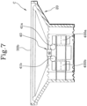
- the description also relates to a sound diffuser "C" comprising a housing 20.
- the sound diffuser “C” also comprises a radiant structure 30 comprising a suspension 30a connected to the housing 20 and a radiator 30b connected to the suspension 30a.
- the suspension 30a is configured to allow the radiator 30b to oscillate relative to the housing 20.
- the radiator 30b is operatively coupled to the at least one magnet 400a in such a way that a movement of the magnet 400a along the movement direction "M1" parallel to the longitudinal axis "A" corresponds to an oscillation of the radiator 30b along the longitudinal axis "A".
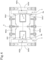
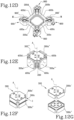
- the rotary members 41a, 41b are pivoted by means of pins.
- the rotary members 41a, 41b of the pair are juxtaposed along an alignment direction transversal to the longitudinal axis "A".
- the rotary members 41a, 41b are counter-rotating to each other in response to the movement of the at least one magnet 400a along the movement direction "M1".
- the rotary members 41a, 41b of the pair are positioned symmetrically relative to the connecting body 42.
- the connecting body 42 is operatively connected to the rotary members 41a, 41b of the pair of rotary members in such a way that a rotation of the rotary members 41a, 41b corresponds to a movement (in reciprocating translation) of the connecting body 42, as described below.
- the mechanical transmission constitutes a homokinetic inverter so that a movement of the at least one magnet 400a along the movement direction "M1" in a first direction, corresponds to a simultaneous movement in a second direction, opposite to the first direction, of the radiator 30b along the longitudinal axis "A". In this situation, the stroke of the radiator 30b and the stroke of the at least one magnet 400a have a different amplitude to each other.
- the amplitude of these movements may be equal to or different (that is, a translation of the radiator 30b by a first amplitude, corresponds to a translation of the magnet 400a by a second amplitude, wherein the first amplitude and the second amplitude may be equal, or the first amplitude may be less than or greater than the second amplitude) and this means that the transmission ratio given by the homokinetic inverter is unitary or not unitary.
- the mass of the radiator 30b is less than that of the magnet 400a (and of the transducer 100) and the amplitude of the stroke of the radiator 30a is correspondingly greater than that of the magnet 400a.
- the rotary members 41a, 41b of the pair each have a point of connection to a respective compensating plate 50 in such a way that the latter extends between the connecting point and the connecting body 42.
- the rotary members 41a, 41b of the pair are connected to it by respective compensating plates 50 in such a way that a translation of the supporting body 600 corresponds to a rotation of the rotary members 41a, 41b.
- the rotary members 41a, 41b transmit, by means of the compensating plates 50, the motion to the connecting body 42 which translates along a direction parallel to the movement direction "M1".
- the connecting body 42 is lowered whilst, if the at least one magnet 400a lowers, the connecting body 42 rises.
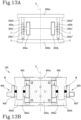
- the transducer 100 comprises a further magnet 400b movable simultaneously with the magnet 400a.
- the further magnet 400b is movable with reciprocating motion along a further movement direction "M2" parallel to the movement direction "M1".
- the mechanical transmission comprises a further actuating member 60 interposed between the further magnet 400b and the radiator 30b for moving the radiator 30b in the opposite direction relative to the further magnet 400b.
- the further actuating member 60 also constitutes a homokinetic inverter.
- the suspension 30a is configured to allow the radiator 30b to move, in particular to move with reciprocating motion.
- the method then comprises a step of transmitting the movement of the magnet 400a to the radiator 30b by means of the mechanical transmission.
- the mechanical transmission defines a non-unitary transmission ratio wherein the stroke of the radiator 30b has an amplitude different from the amplitude of the stroke of the magnet 400a.
- the mechanical transmission defines a unitary transmission ratio wherein the stroke of the radiator 30b has an amplitude equal to the amplitude of the stroke of the magnet 400a.
- the first magnet 400a and the second magnet 400b have the same pole facing the first rectilinear portion 200a and the second rectilinear portion 200b and the third magnet 400c and the fourth magnet 400d have the same pole facing the third rectilinear portion 200c and the rectilinear portion 200d.
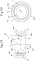
- the core comprises an upper portion and a lower portion.
- the upper portion and the lower portion cooperate to form the central portion 300a of the core, around which the coil 200 is wound, and which extends along the longitudinal axis A.
- the upper portion and the lower portion define a seat for housing the coil 200.
- the core protrudes transversely to the longitudinal axis A and away from the longitudinal axis so as to define an upper protrusion zone, which includes the upper sub-portion 300c' of the inner lateral portion 300c, and a lower protrusion zone, which comprises the bottom sub-portion 300c" of the inner lateral portion 300c.
- the upper sub-portion 300c' and the lower sub-portion 300c" then move towards each other along a direction parallel to the longitudinal axis A for winding at least partially the sides (or walls) of the coil 200 facing towards the air gap T.
- the upper sub- portion 300c' and the lower sub-portion 300c" cooperate to define the slot I, which surrounds the longitudinal axis A.
- the upper sub-portion 300c' and the lower sub-portion 300c" can cooperate to wrap around an entire perimeter of the coil 200 except the point in which the slot I is made.
- the slot I can surround the entire perimeter of the coil 200 except the in the points in correspondence with the curved connection sections.
- the coil 200 is embedded within (or covered by) the ferromagnetic circuit 300 except for the portion close to the slot I which, on the other hand, faces directly the air gap T (i.e. faces directly on the plurality of air gaps).
- the first 200a, the second 200b, the third 200c and the fourth 200d rectilinear portion of the coil 200 are placed laterally to the central portion 300a of the core, i.e. the first 200a, the second 200b, the third 200c and the fourth 200d rectilinear portion of the coil 200 wrap around the central portion 300a of the core.
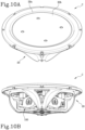
- the acoustic diffuser C comprises a radiator 30b, a suspension 30a and a further radiator 30b' and a further suspension 30a'.
- the actuation member 40 comprises a connecting body 42 connected to the radiator 30b and a further connecting body 42' connected to the further radiator 30b'.
Landscapes
- Engineering & Computer Science (AREA)
- Physics & Mathematics (AREA)
- Acoustics & Sound (AREA)
- Signal Processing (AREA)
- Manufacturing & Machinery (AREA)
- Multimedia (AREA)
- Electromagnetism (AREA)
- Audible-Bandwidth Dynamoelectric Transducers Other Than Pickups (AREA)
- Obtaining Desirable Characteristics In Audible-Bandwidth Transducers (AREA)
- Electrostatic, Electromagnetic, Magneto- Strictive, And Variable-Resistance Transducers (AREA)
Applications Claiming Priority (3)
| Application Number | Priority Date | Filing Date | Title |
|---|---|---|---|
| IT102021000032906A IT202100032906A1 (it) | 2021-12-29 | 2021-12-29 | Diffusore acustico e metodo per estendere la risposta alle basse frequenze di un diffusore acustico. |
| IT102021000032897A IT202100032897A1 (it) | 2021-12-29 | 2021-12-29 | Trasduttore per un diffusore acustico e metodo per la produzione del trasduttore. |
| EP22216753.8A EP4207809B1 (de) | 2021-12-29 | 2022-12-27 | Schalldiffusor und verfahren zur herstellung eines schalldiffusors |
Related Parent Applications (2)
| Application Number | Title | Priority Date | Filing Date |
|---|---|---|---|
| EP22216753.8A Division EP4207809B1 (de) | 2021-12-29 | 2022-12-27 | Schalldiffusor und verfahren zur herstellung eines schalldiffusors |
| EP22216753.8A Division-Into EP4207809B1 (de) | 2021-12-29 | 2022-12-27 | Schalldiffusor und verfahren zur herstellung eines schalldiffusors |
Publications (2)
| Publication Number | Publication Date |
|---|---|
| EP4539503A2 true EP4539503A2 (de) | 2025-04-16 |
| EP4539503A3 EP4539503A3 (de) | 2025-07-23 |
Family
ID=84602605
Family Applications (2)
| Application Number | Title | Priority Date | Filing Date |
|---|---|---|---|
| EP22216753.8A Active EP4207809B1 (de) | 2021-12-29 | 2022-12-27 | Schalldiffusor und verfahren zur herstellung eines schalldiffusors |
| EP25153194.3A Pending EP4539503A3 (de) | 2021-12-29 | 2022-12-27 | Schalldiffusor und verfahren zur diffusion eines schalls durch einen schalldiffusor |
Family Applications Before (1)
| Application Number | Title | Priority Date | Filing Date |
|---|---|---|---|
| EP22216753.8A Active EP4207809B1 (de) | 2021-12-29 | 2022-12-27 | Schalldiffusor und verfahren zur herstellung eines schalldiffusors |
Country Status (4)
| Country | Link |
|---|---|
| US (2) | US12309566B2 (de) |
| EP (2) | EP4207809B1 (de) |
| JP (1) | JP2023098870A (de) |
| CN (1) | CN116367064A (de) |
Families Citing this family (1)
| Publication number | Priority date | Publication date | Assignee | Title |
|---|---|---|---|---|
| EP4550839A1 (de) | 2023-11-03 | 2025-05-07 | Powersoft SpA | Lautsprecher mit rollaufhängungsvorrichtung |
Citations (4)
| Publication number | Priority date | Publication date | Assignee | Title |
|---|---|---|---|---|
| EP0508570A2 (de) | 1991-03-11 | 1992-10-14 | Bose Corporation | Permanentmagnetwandler |
| US20150256911A1 (en) | 2014-03-07 | 2015-09-10 | Bose Corporation | Elastomeric Torsion Bushings for Levered Loudspeakers |
| IT202100001487A1 (it) | 2021-01-26 | 2022-07-26 | Powersoft S P A | Dispositivo acustico |
| IT202200026061A1 (it) | 2022-12-20 | 2024-06-20 | Powersoft S P A | Altoparlante e metodo per diffondere un suono. |
Family Cites Families (12)
| Publication number | Priority date | Publication date | Assignee | Title |
|---|---|---|---|---|
| NL104049C (de) * | 1954-10-28 | |||
| JPS5723994Y2 (de) * | 1976-12-03 | 1982-05-24 | ||
| JPS6022346B2 (ja) | 1976-12-23 | 1985-06-01 | 富士通株式会社 | フオトマスクのパタ−ン修正方法 |
| US5546469A (en) * | 1994-08-15 | 1996-08-13 | Donahoe; Danny T. | Sound transducer |
| US5802193A (en) * | 1997-04-08 | 1998-09-01 | Kieltyka; William J. | Outdoor loudspeaker system |
| GB0122732D0 (en) | 2001-09-20 | 2001-11-14 | Isis Innovations Ltd | Electromechanical transducer linear compressor and radio transmission antenna |
| US8295536B2 (en) * | 2010-03-31 | 2012-10-23 | Bose Corporation | Moving magnet levered loudspeaker |
| US8565461B2 (en) | 2011-03-16 | 2013-10-22 | Cochlear Limited | Bone conduction device including a balanced electromagnetic actuator having radial and axial air gaps |
| US10028062B2 (en) * | 2013-03-15 | 2018-07-17 | Bose Corporation | Driving plural armatures with a common stator |
| US9601969B2 (en) | 2014-03-07 | 2017-03-21 | Bose Corporation | Inhibiting rocking of loads driven by plural levers |
| WO2016020835A1 (en) * | 2014-08-04 | 2016-02-11 | Katz David Micah | Electromechanical transducer with non-circular voice coil |
| EP3777238A1 (de) * | 2018-04-11 | 2021-02-17 | Dali A/S | Lautsprechereinheit mit doppelter schwingspule |
-
2022
- 2022-12-27 EP EP22216753.8A patent/EP4207809B1/de active Active
- 2022-12-27 EP EP25153194.3A patent/EP4539503A3/de active Pending
- 2022-12-28 US US18/147,211 patent/US12309566B2/en active Active
- 2022-12-28 JP JP2022212207A patent/JP2023098870A/ja active Pending
- 2022-12-29 CN CN202211743385.1A patent/CN116367064A/zh active Pending
-
2025
- 2025-04-22 US US19/186,386 patent/US20250254467A1/en active Pending
Patent Citations (4)
| Publication number | Priority date | Publication date | Assignee | Title |
|---|---|---|---|---|
| EP0508570A2 (de) | 1991-03-11 | 1992-10-14 | Bose Corporation | Permanentmagnetwandler |
| US20150256911A1 (en) | 2014-03-07 | 2015-09-10 | Bose Corporation | Elastomeric Torsion Bushings for Levered Loudspeakers |
| IT202100001487A1 (it) | 2021-01-26 | 2022-07-26 | Powersoft S P A | Dispositivo acustico |
| IT202200026061A1 (it) | 2022-12-20 | 2024-06-20 | Powersoft S P A | Altoparlante e metodo per diffondere un suono. |
Also Published As
| Publication number | Publication date |
|---|---|
| JP2023098870A (ja) | 2023-07-11 |
| CN116367064A (zh) | 2023-06-30 |
| EP4207809A1 (de) | 2023-07-05 |
| EP4207809B1 (de) | 2025-02-26 |
| EP4207809C0 (de) | 2025-02-26 |
| EP4539503A3 (de) | 2025-07-23 |
| US20250254467A1 (en) | 2025-08-07 |
| US12309566B2 (en) | 2025-05-20 |
| US20230209273A1 (en) | 2023-06-29 |
Similar Documents
| Publication | Publication Date | Title |
|---|---|---|
| EP1101273B1 (de) | Tieffrequenzschwinger | |
| US5231336A (en) | Actuator for active vibration control | |
| CA2493603C (en) | Actuator capable of moving in axial and rotational directions | |
| JP5248598B2 (ja) | 機械的振動エネルギーを電気エネルギーに変換するための永久磁石による発電機 | |
| JP3475949B2 (ja) | リニアオシレータ | |
| US5444313A (en) | Electromagnetic actuator having two opposite phase movable parts | |
| JP2002525007A5 (de) | ||
| US20250254467A1 (en) | Sound diffuser and a method for diffusing a sound through a sound diffuser | |
| KR20110120242A (ko) | 진동 발생 장치 | |
| JPH07248041A (ja) | 油圧式防振装置 | |
| WO2007001042A1 (ja) | 振動アクチュエータ | |
| CA2085920C (en) | Rubber mount | |
| JP3404139B2 (ja) | 電磁アクチュエータ | |
| WO2020027157A1 (ja) | リニア振動アクチュエータ | |
| IT202100032897A1 (it) | Trasduttore per un diffusore acustico e metodo per la produzione del trasduttore. | |
| KR20100006718A (ko) | 진동 발생 장치 | |
| JPH11351321A (ja) | 能動型制振器 | |
| CN120855808A (zh) | 线性振动马达 | |
| JP2012165554A (ja) | リニアアクチュエータ | |
| JPH06300077A (ja) | 流体封入式防振装置 | |
| JPH0575642U (ja) | ダブルソレノイド式加振器 |
Legal Events
| Date | Code | Title | Description |
|---|---|---|---|
| PUAI | Public reference made under article 153(3) epc to a published international application that has entered the european phase |
Free format text: ORIGINAL CODE: 0009012 |
|
| STAA | Information on the status of an ep patent application or granted ep patent |
Free format text: STATUS: THE APPLICATION HAS BEEN PUBLISHED |
|
| AC | Divisional application: reference to earlier application |
Ref document number: 4207809 Country of ref document: EP Kind code of ref document: P |
|
| AK | Designated contracting states |
Kind code of ref document: A2 Designated state(s): AL AT BE BG CH CY CZ DE DK EE ES FI FR GB GR HR HU IE IS IT LI LT LU LV MC ME MK MT NL NO PL PT RO RS SE SI SK SM TR |
|
| PUAL | Search report despatched |
Free format text: ORIGINAL CODE: 0009013 |
|
| AK | Designated contracting states |
Kind code of ref document: A3 Designated state(s): AL AT BE BG CH CY CZ DE DK EE ES FI FR GB GR HR HU IE IS IT LI LT LU LV MC ME MK MT NL NO PL PT RO RS SE SI SK SM TR |
|
| RIC1 | Information provided on ipc code assigned before grant |
Ipc: H04R 9/02 20060101AFI20250617BHEP |