EP4207809B1 - Schalldiffusor und verfahren zur herstellung eines schalldiffusors - Google Patents
Schalldiffusor und verfahren zur herstellung eines schalldiffusors Download PDFInfo
- Publication number
- EP4207809B1 EP4207809B1 EP22216753.8A EP22216753A EP4207809B1 EP 4207809 B1 EP4207809 B1 EP 4207809B1 EP 22216753 A EP22216753 A EP 22216753A EP 4207809 B1 EP4207809 B1 EP 4207809B1
- Authority
- EP
- European Patent Office
- Prior art keywords
- magnet
- coil
- longitudinal axis
- magnets
- along
- Prior art date
- Legal status (The legal status is an assumption and is not a legal conclusion. Google has not performed a legal analysis and makes no representation as to the accuracy of the status listed.)
- Active
Links
Images


Classifications
-
- H—ELECTRICITY
- H04—ELECTRIC COMMUNICATION TECHNIQUE
- H04R—LOUDSPEAKERS, MICROPHONES, GRAMOPHONE PICK-UPS OR LIKE ACOUSTIC ELECTROMECHANICAL TRANSDUCERS; DEAF-AID SETS; PUBLIC ADDRESS SYSTEMS
- H04R27/00—Public address systems
-
- H—ELECTRICITY
- H04—ELECTRIC COMMUNICATION TECHNIQUE
- H04R—LOUDSPEAKERS, MICROPHONES, GRAMOPHONE PICK-UPS OR LIKE ACOUSTIC ELECTROMECHANICAL TRANSDUCERS; DEAF-AID SETS; PUBLIC ADDRESS SYSTEMS
- H04R11/00—Transducers of moving-armature or moving-core type
- H04R11/02—Loudspeakers
-
- H—ELECTRICITY
- H04—ELECTRIC COMMUNICATION TECHNIQUE
- H04R—LOUDSPEAKERS, MICROPHONES, GRAMOPHONE PICK-UPS OR LIKE ACOUSTIC ELECTROMECHANICAL TRANSDUCERS; DEAF-AID SETS; PUBLIC ADDRESS SYSTEMS
- H04R31/00—Apparatus or processes specially adapted for the manufacture of transducers or diaphragms therefor
- H04R31/006—Interconnection of transducer parts
-
- H—ELECTRICITY
- H04—ELECTRIC COMMUNICATION TECHNIQUE
- H04R—LOUDSPEAKERS, MICROPHONES, GRAMOPHONE PICK-UPS OR LIKE ACOUSTIC ELECTROMECHANICAL TRANSDUCERS; DEAF-AID SETS; PUBLIC ADDRESS SYSTEMS
- H04R7/00—Diaphragms for electromechanical transducers; Cones
- H04R7/16—Mounting or tensioning of diaphragms or cones
- H04R7/18—Mounting or tensioning of diaphragms or cones at the periphery
-
- H—ELECTRICITY
- H04—ELECTRIC COMMUNICATION TECHNIQUE
- H04R—LOUDSPEAKERS, MICROPHONES, GRAMOPHONE PICK-UPS OR LIKE ACOUSTIC ELECTROMECHANICAL TRANSDUCERS; DEAF-AID SETS; PUBLIC ADDRESS SYSTEMS
- H04R9/00—Transducers of moving-coil, moving-strip, or moving-wire type
- H04R9/02—Details
- H04R9/04—Construction, mounting, or centering of coil
- H04R9/045—Mounting
-
- H—ELECTRICITY
- H04—ELECTRIC COMMUNICATION TECHNIQUE
- H04R—LOUDSPEAKERS, MICROPHONES, GRAMOPHONE PICK-UPS OR LIKE ACOUSTIC ELECTROMECHANICAL TRANSDUCERS; DEAF-AID SETS; PUBLIC ADDRESS SYSTEMS
- H04R9/00—Transducers of moving-coil, moving-strip, or moving-wire type
- H04R9/06—Loudspeakers
-
- H—ELECTRICITY
- H04—ELECTRIC COMMUNICATION TECHNIQUE
- H04R—LOUDSPEAKERS, MICROPHONES, GRAMOPHONE PICK-UPS OR LIKE ACOUSTIC ELECTROMECHANICAL TRANSDUCERS; DEAF-AID SETS; PUBLIC ADDRESS SYSTEMS
- H04R9/00—Transducers of moving-coil, moving-strip, or moving-wire type
- H04R9/02—Details
- H04R9/025—Magnetic circuit
Definitions
- This invention relates to a sound diffuser and a method for making a sound diffuser.
- the field of the invention is that of sound reproduction systems, and in particular sound diffusers in which the need is increasingly felt to have a product which is able to provide good sound performance levels and, at the same time, is able to maintain small dimensions.
- the need is increasingly felt to obtain compact diffusers but which, at the same time, are able to guarantee high acoustic performance levels in terms of the value of the SPL (Sound Pressure Level) parameter.
- the sound diffusers comprise an electro-mechanical transducer in which a coil or the magnets are movable.
- a further drawback is due to the arrangement of the magnets relative to the coil. During the movement of the magnets, they are not kept fully immersed in the magnetic field generated. In this situation, the portions not immersed in the magnetic field cause losses which affect the overall efficiency of the sound transducer.
- the technical purpose of the invention is therefore to provide a sound diffuser and a method for making a sound diffuser which are able to overcome the drawbacks of the prior art.
- the aim of the invention is therefore to provide a sound diffuser having a transducer which allows high mechanical movements of the sound membrane of the diffuser associated with it to be generated without increasing its overall dimensions, especially the dimensions in the movement direction of the magnets.
- a further aim of the invention is to provide a sound diffuser having a transducer which is able to generate high forces and movements with a low energy consumption.
- a further aim of the invention is to provide a method of making a sound diffuser which is simple and efficient.
- the transducer comprises a coil including a plurality of turns each lying in a respective plane transversal to a longitudinal axis.
- the turns are juxtaposed along the longitudinal axis.
- the turns of the coil can surround the longitudinal axis.
- the transducer also comprises a ferromagnetic circuit including a core, provided with a central portion around which the coil is wound, and an outer lateral portion located at the side of the coil and at least partly surrounding the coil.
- the outer lateral portion is separated from the core by an air gap, that is to say, by air.
- the air gap is extended longitudinally.
- the transducer also comprises four magnets located inside the air gap.
- Each magnet is a permanent magnet, that is to say, a magnetized body which is able to create its own magnetic field.
- the magnet has a first end and a second end.
- the magnet has a south pole and a north pole extending between the first end and the second end parallel to the longitudinal axis.
- the magnet has two opposite faces having opposite polarization.
- the magnet is movable, inside the air gap, along a movement direction parallel to the longitudinal axis.
- the movement of the magnet along the movement direction is induced by a magnetic energizing field generated by energizing the coil, that is to say, by the passage of an electric current inside the coil.
- transducer An example of a transducer is disclosed by patent document US2015256911 A1 , wherein there is a pair of coils, each wound around a core portion; the two core portions are placed side by side so as to define an air gap within which a movable magnet is placed. Therefore, the coils are placed side by side and each of the two core portions defines, for the other core portion, an outer lateral portion which, in fact, is located at the side of one of the two coils and cooperates with the other core portion to define the air gap.
- the transducer has only one coil; the coil is wound around a core portion (in particular, around the central portion) and the outer side portion, with which the core cooperates to define the air gap, is not surrounded by further coils, as it is instead in US2015256911 A1 .
- a further difference is that the turns of the coil are wound around the longitudinal axis; therefore, when the transducer is used in an acoustic diffuser which includes a radiator, movable with reciprocating motion along the longitudinal axis, the coil is aligned with the longitudinal axis, i.e. with the axis along which the radiator oscillates.
- the coil is a single coil.
- the central portion extends along the longitudinal axis.
- the ferromagnetic circuit might also comprise an inner lateral portion located at the side of the coil and interposed between the coil and the at least one magnet.
- the inner lateral portion has a high magnetic permeability zone close to (or facing) the coil.
- the high magnetic permeability zone is defined by a slot transversal to the longitudinal axis such as to divide the inner lateral portion into an upper sub-portion and a lower sub-portion juxtaposed along a direction parallel to the longitudinal axis and defining respective pole expansions directed towards the air gap.
- the upper sub-portion and the lower sub-portion of the inner lateral portion are made in one piece with the core and jut out relative to the central portion towards the outer lateral portion winding around the coil.
- the upper sub-portion and the lower sub-portion extend in such a way as to wind almost entirely around the coil leaving free only the area close to the slot in such a way that the coil can face, in that zone, towards the air gap and the magnet.
- the core extends along the longitudinal axis, to define the central portion.
- the central portion extends along the longitudinal axis.
- the core may protrude transversely with respect to the longitudinal axis and away from the longitudinal axis, to define an upper protrusion zone and a lower protrusion zone.
- the upper protrusion zone comprises the upper sub-portion
- the lower protrusion zone comprises the lower sub-portion.
- the upper protrusion zone and the lower protrusion zone are located symmetrically with respect to an axis transversal to the longitudinal axis and passing through a center of the coil.
- the protrusion zones surrounds the coil at the bottom and at the top symmetrically with respect to a plane transverse to the longitudinal axis and passing through a center of the coil, i.e. the upper protrusion zone and the lower protrusion zone have the same extension symmetrically to a plane transverse to the longitudinal axis and passing through a center of the coil.
- the coil comprises a plurality of rectilinear portions, transverse to the longitudinal axis.
- the outer lateral portion comprises a plurality of parts surrounding the coil.
- the plurality of parts cooperates with the corresponding plurality of rectilinear portions to define a plurality of air gaps.
- the diffuser, or the transducer comprises four magnets; each magnet of the plurality of magnets is located in a respective air gap of the plurality of air gaps.
- each magnet is located between a part of the plurality of parts of the outer lateral portion and a rectilinear portion of the plurality of rectilinear portions of the coil.
- the magnets of the plurality of magnets are arranged as the sides of a regular polygon.
- the regular polygon is inscribed in a circle having a center passing through the longitudinal axis.
- the plurality of rectilinear portions comprises a first, a second, a third and a fourth rectilinear portion.
- the plurality of rectilinear portions in particular the first, second, third and fourth rectilinear portions, are joined together by respective curved connection sections.
- the first and second rectilinear portions are be mutually facing.
- the third and fourth rectilinear portions are mutually facing.
- the first, second, third and fourth rectilinear portions lie on a same plane transverse to the longitudinal axis.
- the plurality of parts of the outer lateral portion includes a first, a second, a third and a fourth part.
- the first, the second, the third and the fourth part can be separate from each other and can be placed laterally to the coil symmetrically with respect to the longitudinal axis.
- the plurality of magnets includes a first magnet, a second magnet, a third magnet and a fourth magnet.
- the first magnet is placed between the first rectilinear portion and the first part of the outer side portion; the second magnet is placed between the second rectilinear portion and the second part; the third magnet is placed between the third rectilinear portion and the third part; the fourth magnet is placed between the fourth rectilinear portion and the fourth part.
- the first, second, third and fourth magnets are movable along respective movement directions, parallel to the longitudinal axis.
- each magnet i.e. the first, the second, the third magnet and the fourth magnet
- each magnet extends along a direction transversal to the longitudinal axis and parallel to the respective rectilinear portion.
- the magnets of the plurality of magnets are joined together by respective angular elements.
- the angular elements are arranged in correspondence with the curved connection sections of the coil, so to form a rigid structure movable along the longitudinal direction.
- the first rectilinear portion and the first magnet have the same transversal extension to the longitudinal axis, as well as the second rectilinear portion and the second magnet, the third rectilinear portion and the third magnet and the fourth rectilinear portion and the fourth magnet.
- the sound diffuser comprises a guide device, in particular four guide devices.
- Each guide device can be coupled to an angular element of the plurality of angular elements, to allow the movement of each magnet of the plurality of magnets along the respective movement direction.
- the guide device can be a single guide device.
- Each guide device is configured to constrain the movement of the magnets along the movement direction, while preventing a movement in a direction transversal to the longitudinal axis.
- Coupled means, for example, that an external surface of the guide device can coincide with the angular element, or that the angular element defines an external surface of the guide device, or that the angular element is connected to a bush which defines an external surface of the guide device.
- Each guide device comprises an internal surface extending around guide axis longitudinally oriented.
- Each guide device comprises an external surface, extending around the guide axis and surrounding the internal surface to define a cavity.
- Each guide device may include a plurality of ball bearings, arranged in the cavity, in contact with the internal surface and the external surface to roll on them moving longitudinally in response to a relative movement between the internal surface and the external surface.
- each guide device comprises an elastic element, for example a spring, closed on itself to form a ring, arranged in the cavity in contact with the internal surface and the external surface, to roll on them moving longitudinally in response to a relative movement between the internal surface and the external surface.
- the internal surface can be connected (directly or indirectly) to the core and the external surface can be connected (directly or indirectly) to a magnet, i.e. at least one magnet, or vice versa.
- the outer surface is connected to a pair of magnets of the plurality of magnets and the inner surface is connected to the core, or vice versa.
- the internal surface and the external surface develop according to various shapes along the longitudinal direction (for example, they can develop along respective planes parallel to the longitudinal axis). Therefore, the elastic element can be inserted within the cavity formed by the internal surface and the external surface, so as to roll between the surfaces longitudinally. In this case, the elastic element may not be closed on itself to form a ring.
- the guide device comprises a retaining band, preferably metallic, which can be made according to one or more aspects of the present description.
- the retaining band is configured to constrain the movement of the magnets along the direction of movement and to prevent a movement along a direction transverse to the direction of movement.
- the retaining band can be connected to the angular elements.
- the retaining band may comprise first, second, third and fourth sections defining a plurality of sections of the retaining band. A pair of sections of the plurality of sections of the retaining band can be connected, at one end of thereof, to an angular element.
- Each section of the plurality of sections of the retaining band can be connected, in a central region thereof, preferably jointly, to a corresponding part of the plurality of parts of the outer lateral portion, for example via a connecting element.
- Each section is elastically deformable, so that a movement of an angular element corresponds to a bending of the sections of the retaining band to which the angular element is connected.
- each magnet of the plurality of magnets has a first end and a second end. The first end is opposite the second end in the longitudinal direction.
- Each magnet includes a south pole and a north pole.
- each north pole and each south pole extend between the first end and the second end parallel to the longitudinal axis.
- each magnet has a first side and a second side, opposite to the first side.
- the first side and the second side extend longitudinally, i.e., along a direction parallel to the longitudinal axis.
- each magnet comprises a south pole, located on one between the first and the second side of the magnet, and a north pole, located on the other between the first and the second side of the magnet.
- the first magnet and the second magnet have the same pole facing the coil.
- the third magnet and the fourth magnet have the same pole facing the coil.
- the sound diffuser i.e. the transducer
- the sound diffuser comprises a thermally conductive resin matrix, which incorporates the coil and at least part of the core.
- the method comprises a step of providing angular elements in correspondence with the curved connection sections of the coil to join the magnets of the plurality of magnets together.
- the method can comprise a step of providing four guide devices, each of which being coupled to an angular element of a plurality of angular elements.
- the method can comprise a step of guiding, by the guide devices, the plurality of magnets along the respective movement direction.
- Each guide device can be made according to one or more aspects of the present description.
- the mechanical transmission in particular the actuating member, constitutes a homokinetic inverter.
- the amplitude of the movement of the radiator and the amplitude of the movement of the magnet can be the same or different; in other words, the transmission ratio can be unitary or non-unitary.
- the plurality of actuating members can comprise a first actuating member, for moving the radiator with respect to the first magnet, a second actuating member, for moving the radiator with respect to the second magnet, a third actuating member for moving the radiator with respect to the third magnet and a fourth actuating member for moving the radiator relative to the fourth actuating member.
- the numeral 100 denotes a transducer for a sound diffuser "C".
- the transducer 100 comprises a coil 200 including a plurality of turns 201 each lying in a respective plane ⁇ transversal to a longitudinal axis "A".
- the turns 201 are juxtaposed along the longitudinal axis "A".
- the transducer 100 also comprises a ferromagnetic circuit 300 including a core provided with a central portion 300a around which the coil 200 is wound.
- the ferromagnetic circuit 300 also comprises an outer lateral portion 300b located at the side of the coil 200 and at least partly surrounding the coil 200.
- the outer lateral portion 300b is separated from the core by an air gap "T" that extends longitudinally.
- the transducer 100 also comprises at least one magnet 400a located inside the air gap "T".
- the magnet 400a is a permanent magnet, that is to say, a magnetized body which is able to create its own magnetic field.
- the magnet 400a is movable along a movement direction "M1" parallel to the longitudinal axis "A".
- the movement of the magnet 400a along the movement direction M1 is induced by a magnetic energizing field generated by energizing (that is to say, by the passage of current inside) the coil 200.
- the magnet 400a has a first end 400a' and a second end 400a".
- the magnet 400a has a south pole “Sa” and a north pole “Na” extending between the first end 400a' and the second end 400a" parallel to the longitudinal axis "A".
- the magnet 400a substantially has two opposite faces corresponding, respectively, to the south pole "Sa” and the north pole "Na”.
- the ferromagnetic circuit 300 also comprises an inner lateral portion 300c located at the side of the coil 200 and interposed between the coil 200 and the at least one magnet 400a.
- the inner lateral portion 300c has a high magnetic permeability zone close to the coil 200.
- the high magnetic permeability zone is defined by a slot "I" transversal to the longitudinal axis "A” such as to divide the inner lateral portion 300c into an upper sub-portion 300c' and a lower sub-portion 300c" juxtaposed along a direction parallel to the longitudinal axis "A” and defining respective pole expansions facing towards the air gap "T".
- the upper sub-portion 300c' and the lower sub-portion 300c" of the inner lateral portion 300c' may be made in one piece with the core and jut out relative to the central portion 300a towards the outer lateral portion 300b.
- the inner lateral portion 300c and the central portion 300a are shaped in such a way that the ferromagnetic circuit 300 has in cross-section a substantially H-shape.
- the upper sub-portion 300c' and the lower sub-portion 300c" act in conjunction to wind around almost the entire coil 200 except the point at which the slot "I" is made.
- the coil 200 is embedded into (or covered by) the ferromagnetic circuit 300 except for the portion close to the slot "I" which, on the other hand, faces directly the air gap "T".
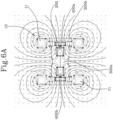
- the presence of the slot is particularly advantageous since it creates a zone with low reluctance (or high permeability) such as to allow an extension of the magnetic field as shown in Figure 6B .
- the at least one magnet 400a is in a position of equilibrium inside the air gap "T", that is to say, in a position in which it substantially fully faces the slot "I".
- a current is made to flow inside the coil 200, it induces the magnetic energizing field which interacting with the magnetic field of the magnet 400a induces a movement along the movement direction "M1".
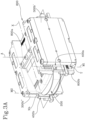
- the inner lateral portion 300c and/or the central portion 300a comprise a plurality of plates aligned with each other along a direction transversal to the longitudinal axis "A" ( Figure 3B ).
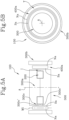
- Figures 5A and 5B show a possible embodiment of the transducer 100 wherein the transducer 100 has a substantially radial extension.
- the coil 200 is substantially circular in shape and is wound around the central portion 300a of the core.
- the outer lateral portion 300b has an annular shape forming an outer ring surrounding the coil 200.
- the outer ring is concentric with the coil 200 and forms with the latter a circular crown defining the air gap "T".
- the at least one magnet 400a also has an annular shape and defines a magnetic ring entirely surrounding the coil 200.
- the magnetic ring is positioned inside the air gap "T" in such a way that one between the north pole "Na” and the south pole "Sa” is entirely facing towards the coil 200 for the entire circular extension of the coil 200, whilst the other pole faces towards the outer lateral wall 300b.
- the magnetic ring is divided, along a direction parallel to the longitudinal axis "A", into two parts defining, respectively, the north pole "Na” and the south pole “Sa” of the magnet 400a each of which entirely faces one of either the coil 200 or the outer lateral wall 300b.
- the south pole “Sa” faces the coil 200 whilst the north pole “Na” faces the outer lateral wall 300b.
- the coil 200, the outer ring and the magnetic ring are concentric and centred relative to the longitudinal axis "A".
- the inner lateral portion 300c also has an annular shape defining an inner ring concentric with the outer ring.
- the inner ring is interposed between the coil 200 and the magnetic ring.
- the slot "I" extends annularly in such a way as to define the upper sub-portion 300c' and the lower sub-portion 300c".
- the upper sub-portion 300c' and the lower sub-portion 300c" project from the central portion 300a in such a way as to cover and wind around the coil 200 respectively above and below.
- the upper sub-portion 300c' and the lower sub-portion 300c" then move towards each other along a direction parallel to the longitudinal axis "A" for winding at least partly around the faces (or walls) of the coil 200 facing towards the air gap "T".
- the coil 200 In use, therefore, when the coil 200 is energized by a current, an magnetic energizing field is generated which interacts with the magnetic field of the magnetic ring causing its movement along the movement direction "M1". This movement causes a movement or oscillation of the radiator 30b of the sound diffuser "C" to which the transducer 100 is associated.
- the radial architecture of the transducer 100 described above makes it possible to eliminate practically all the losses since the coil 200 is entirely surrounded and wound around by the ferromagnetic circuit 300.
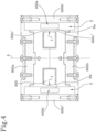
- the coil 200 has an elongate shape along a main direction of extension "X" transversal to the longitudinal axis "A".
- the coil 200 comprises a first rectilinear portion 200a parallel to the main direction of extension "X" and a second rectilinear portion 200b facing the first rectilinear portion 200a and parallel to the main direction of extension "X".
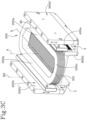
- the first and second rectilinear portions 200a, 200b are joined together by respective connecting portions 200c which are rounded and transversal to the main direction of extension "X" ( Figure 3C ).
- the outer lateral portion 300b comprises a first and a second part 300b', 300b′′′ which are separate from each other and located to the side of the coil 200 symmetrically relative to the longitudinal axis "A".
- the first and second parts 300b', 300b" of the outer lateral portion 300b face, respectively, the first rectilinear portion 200a and the second rectilinear portion 200b.
- the first and second parts 300b', 300b" of the outer lateral portion 300b are spaced from the first rectilinear portion 200a and the second rectilinear portion 200b of the coil 200 from the air gap "T".
- the first and second parts 300b', 300b" of the outer lateral portion 300b have, along the main direction of extension "X", substantially the same extension as the first rectilinear portion 200a and the second rectilinear portion 200b of the coil 200.
- the transducer 100 also comprises a further magnet 400b located inside the air gap "T" symmetrically to the magnet 400a relative to the longitudinal axis "A".
- the further magnet 400b is a permanent magnet.
- one between the magnet 400a and the further magnet 400b is interposed between the first rectilinear portion 200a of the coil 200 and the first part 300b' of the outer lateral portion 300b whilst the other between the magnet 400a and the further magnet 400b is interposed between the second rectilinear portion 200b of the coil 200 and the second part 300b" of the outer lateral portion 300b.
- the further magnet 400b is movable along a movement direction "M2" parallel to the longitudinal axis "A".
- both the magnet 400a and the further magnet 400b are moved along the respective movement directions "M1", “M2" (parallel to each other) to cause an oscillation of the radiator 30b of the sound diffuser "C" in which the transducer 100 is mounted.
- the magnet 400a and the further magnet 400b respectively face the first and second rectilinear portions 200a, 200b of the coil 200 and have an elongate shape extending along respective axial directions parallel to the main direction of extension "X".
- the first rectilinear portion 200a and the magnet 400a have the same axial extension and the second rectilinear portion 200b and the further magnet 400b have the same axial extension.
- the coil 200 is symmetrical and therefore the axial extension of the first rectilinear portion 200a is equal to that of the second rectilinear portion 200a and therefore the axial extension of the magnet 400a is equal to that of the further magnet 400b.
- the magnet 400a and the further magnet 400b both face the north pole “Na”, “Nb” to the coil 200.
- the magnet 400a and the further magnet 400b could both face the south pole “Sa”, “Sb” on the coil 200 and, consequently, the north pole "Na”, “Nb” to the first and second parts 300b', 300b" of the outer lateral portion 300b.
- the central portion 300a of the ferromagnetic circuit 300 and the inner lateral portion 300c have an elongate shape along the main direction of extension "X".
- the slot "I" is transversal to the longitudinal axis "A” and extends parallel to the main direction of extension "X".
- the slot "I" is such as to divide the lateral portion into an upper part 300c' and into a lower part 300c".
- first and second rectilinear portions 200a, 200b of the coil 200 are immersed in the ferromagnetic circuit 300 substantially along their entire extension whilst the connecting portions 200c protrude from the ferromagnetic circuit 300.
- This aspect is particularly advantageous because it minimises losses and increases the efficiency of the transducer 100.
- the coil 200 extends almost entirely inside the ferromagnetic circuit 300 it is possible to easily compensate (that is to say, minimize) the losses of efficiency given by the connecting portions 200c not immersed in the ferromagnetic circuit 300.
- the magnet 400a and the further magnet 400b are, if current does not flow in the coil 200, in the equilibrium position, that is to say, they are counter-facing the slot "I" made in the inner lateral portion.
- a magnetic energizing field is generated inside the ferromagnetic circuit 300 which is able to disrupt the equilibrium of the magnet 400a and of the further magnet 400b.
- the magnetic energizing field interacts with the magnetic fields generated by the magnet 400a and by the further magnet 400b, causing the latter to move along the respective movement directions "M1", “M2". Consequently, the movement of the magnet 400a and the further magnet 400b causes an oscillation (or translation) of the radiator 30b of the sound diffuser "C" in which the transducer 100 is mounted, allowing the generation of the sound.
- the transducer 100 comprises a supporting body 600 operatively connected to the magnet 400 and to the further magnet 400b to make the movement of the magnet 400a and of the further magnet 400b integral along the respective movement directions "M1", “M2" when the coil 200 is energized.
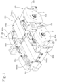
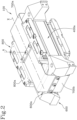
- the supporting body 600 has a closed shape and elongate along the main direction of extension "X" in such a way as to define, symmetrically relative to the longitudinal axis "A" housing seats for the magnet 400a and the further magnet 400b ( Figure 2 ).
- the magnet 400a and the further magnet 400b move simultaneously energized from the magnetic energizing field. Since the magnets 400a, 400b are connected to the supporting body 600, they drive the latter in a translational motion along the longitudinal axis "A". The supporting body 600 is then moved with reciprocating motion along a direction parallel to the longitudinal axis "A" and thus parallel to the movement directions "M1", “M2" of the magnet 400a and of the further magnet 400b.
- the supporting body 600 acts as an upper and lower limit stop for the magnets 400a, 400b in their lowering and raising movement along the movement directions "M1", "M2".
- the supporting body 600 is such that the stroke of the magnets 400a, 400b along the respective movement directions "M1", "M2" is such that the magnets 400a, 400b always remain immersed in the magnetic field generated by the energizing of the coil 200.
- the half-shells 800a, 800b have a "U" shape and are each provided with two flanges designed to engage the outer lateral portion 300b of the ferromagnetic circuit 300.
- the containment space is delimited below and above by the two half-shells 800a, 800b whilst it is laterally delimited by the outer lateral portion 300b of the ferromagnetic circuit 300.
- the supporting body 600 is inserted in the containment space for the parts engaged with the magnet 400a and the further magnet 400b whilst it is outside the containment space for the remaining parts.
- the transducer 100 also comprises a retaining band 700, preferably made of metal, configured to prevent a movement of the supporting body 600 transversely to the longitudinal axis "A".
- the retaining band 700 is configured for constraining the supporting body 600 to translate along a direction parallel to the longitudinal axis "A" following a movement of the at least one magnet 400a.
- the retaining band 700 is elastically deformable in such a way that a movement of the supporting body 600 corresponds to a bending of the retaining band 700, as described in detail below.
- the retaining band 700 surrounds the transducer 100 extending parallel to the main direction of extension "X" and surrounding the transducer 100 entirely.
- the supporting body 600 has a first and a second housing seat 600a, 600b (not visible) made on ends of the supporting body 600 opposite each other along the main direction of extension "X" and configured to stably receive the retaining band 700.
- the retaining band 700 has a first portion 700a extending parallel to the main direction of extension "X" along the first half-shell 800a between the first and second housing seats 600a, 600b.
- the retaining band 700 also has a second portion 700b extending parallel to the main direction of extension "X" along the second half-shell 800b between the first and the second housing seats 600a, 600b.
- the first and second portions 700a, 700b of the retaining band 700 are pivoted to the first and second housing seats 600a, 600b, for example by screws.
- the first and second portions 700a, 700b of the retaining band 700 are also pivoted to the first and second half-shells 800a, 800b, preferably in a central region of them ( Figure 1 ), for example by screws.
- the magnets 400a, 400b are moved along the respective movement directions "M1", “M2” and the supporting body 600 translates as one with them parallel to the longitudinal axis "A"
- the first and second portions 700a, 700b of the retaining band 700 are pivoted to the first and second housing seats 600a, 600b and to the half-shells 800a, 800b, the retaining band 700 undergoes a bending.
- the retaining band 700 allows the movement of the magnets 400a, 400b along the respective movement directions "M1", “M2" and, at the same time, prevents unwanted movement along different directions.
- the retaining band 700 also guarantees compactness and seal of the entire transducer 100.
- the transducer 100 according to the invention therefore has a small size in the movement direction of the at least magnet one 400a (or, if necessary, of the further magnet 400b if present).
- the transducer 100 according to the invention has a high electromechanical efficiency and good strength as well as a considerable construction simplicity.
- the transducer 100 has a moderate cost and a modest use of high-quality magnetic materials, since the transducer 100 allows the latter to work at the optimum point of the energy product of the magnet.
- the invention also relates to a method for making a transducer 100 for a sound diffuser "C".
- the method comprises a step of preparing a transducer 100 comprising a coil 200 provided with a plurality of turns 201 each extending on a respective plane ⁇ transversal to a longitudinal axis "A".
- the turns 201 are juxtaposed along the longitudinal axis "A”.
- the transducer 100 also comprises a ferromagnetic circuit 300 comprising a core provided with a central portion 300a around which the coil 200 is wound and an outer lateral portion 300b located at the side of the coil 20 and separated from the coil 200 by an air gap "T".
- the transducer 100 also comprises at least one magnetizable element.
- the transducer 100 comprises a pair of elements which can be magnetized opposite each other and symmetrical relative to the longitudinal axis "A".
- the method also comprises a step of positioning the magnetizable element in the air gap "T" and a step of preparing, outside the transducer 100, an auxiliary magnetizing circuit 10 configured to magnetize the magnetizable element.
- the auxiliary circuit 10 has an architecture such as that shown in Figure 6A .
- the auxiliary circuit 10 comprises magnetizing coils 11 which are able to create a magnetic field which is able to magnetize the magnetizable element.
- the method then comprises a step of magnetizing the at least one magnetizable element by activating the auxiliary magnetizing circuit 10 in such a way as to make a permanent magnet 400a (or if there is the further magnetizable element, a further permanent magnet 400b).
- the possibility of magnetizing the magnetizable element once inside the transducer 100 makes it possible to facilitate the assembly of the transducer 100.
- the description also relates to a sound diffuser "C" comprising a housing 20.
- the housing 20 has a circular shape in cross section.
- the housing 20 may have, in cross section, any shape.
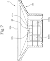
- the sound diffuser “C” also comprises a transducer 100 located inside the housing 20 ( Figure 8 ) and comprising a coil 200 and at least one magnet 400a, preferably a permanent magnet, movable with reciprocating motion along a movement direction "M1" under the action of a magnetic field generated by the coil 200.
- a transducer 100 located inside the housing 20 ( Figure 8 ) and comprising a coil 200 and at least one magnet 400a, preferably a permanent magnet, movable with reciprocating motion along a movement direction "M1" under the action of a magnetic field generated by the coil 200.
- the sound diffuser "C" may comprise a transducer 100 as described above.
- the sound diffuser "C” comprises a transducer 100 according to the embodiment of Figures 1 to 4 .
- the sound diffuser “C” also comprises a radiant structure 30 comprising a suspension 30a connected to the housing 20 and a radiator 30b connected to the suspension 30a.
- the suspension 30a is configured to allow the radiator 30b to oscillate relative to the housing 20.
- the suspension 30a allows the radiator 30b to move with reciprocating motion along a longitudinal axis "A" parallel to the movement direction "M1" of the at least one magnet 400a.
- the radiator 30b is operatively coupled to the at least one magnet 400a in such a way that a movement of the magnet 400a along the movement direction "M1" parallel to the longitudinal axis "A" corresponds to an oscillation of the radiator 30b along the longitudinal axis "A".
- the sound diffuser "C” comprises a mechanical transmission comprising at least one actuating member 40 interposed between at least one magnet 400a and the radiator 30b for moving the radiator 30b in the opposite direction relative to the at least one magnet 400a.
- the actuating member 40 is such that a movement of the magnet 400a along the movement direction "M1" in one direction corresponds to a movement of the radiator 30b along the longitudinal axis "A" in the opposite direction.
- the actuating member 40 comprises a pair of rotary members 41a, 41b pivoted to the transducer 100.
- the rotary members 41a, 41b of the actuating member 40 are each pivoted at a connecting point "P" on the outer lateral wall 300b of the ferromagnetic circuit 300 of the transducer 100 ( Figure 1 ).
- the rotary members 41a, 41b are pivoted by means of pins.
- the rotary members 41a, 41b are associated with the outer lateral wall 300b by means of a conforming mechanism, that is to say, a flexible mechanism which reaches the transmission of force and movement through the elastic deformation of the body of the actuating member 40.
- a conforming mechanism that is to say, a flexible mechanism which reaches the transmission of force and movement through the elastic deformation of the body of the actuating member 40.
- the conforming mechanism may be made as described in Italian patent application No. 102021000001487 in the name of the same Applicant as this invention.
- one end of the conforming mechanism is connected to a passive radiant panel and another end is connected to a mass (for compensation); when this type of conforming mechanism is used in this solution, the first end is connected to the radiator 30b (which in this case has an active role in generating the sound waves) and the other end of the conforming mechanism is connected (directly or indirectly) to the magnet 400a (and therefore to the masses integral with the magnet 400a); in particular, if there are two magnets, there are two conforming mechanisms, one for each magnet.
- the rotary members 41a, 41b of the pair are juxtaposed along an alignment direction transversal to the longitudinal axis "A".
- the rotary members 41a, 41b of the pair are connected to the outer lateral wall 300b of the ferromagnetic circuit 300 in such a way that their connecting points "P" are aligned along an alignment direction transversal to the longitudinal axis "A” and parallel to the main direction of extension "X".
- the rotary members 41a, 41b of the actuating member 40 have a substantially round shape wherein the connecting point "P" occupies a central position.
- the rotary members 41a, 41b are counter-rotating to each other in response to the movement of the at least one magnet 400a along the movement direction "M1".
- the actuating member 40 also comprises a connecting body 42 integral with the radiator 30b.
- the connecting body 42 is movable with reciprocating motion along a direction parallel to the longitudinal axis "A" for moving the radiator 30b.
- the connecting body 42 is interposed between the rotary members 41a, 41b of the pair of rotary members and the radiator 30b.
- the rotary members 41a, 41b of the pair are positioned symmetrically relative to the connecting body 42.
- the connecting body 42 is operatively connected to the rotary members 41a, 41b of the pair of rotary members in such a way that a rotation of the rotary members 41a, 41b corresponds to a movement (in reciprocating translation) of the connecting body 42, as described below.
- the mechanical transmission constitutes a homokinetic inverter so that a movement of the at least one magnet 400a along the movement direction "M1" in a first direction, corresponds to a simultaneous movement in a second direction, opposite to the first direction, of the radiator 30b along the longitudinal axis "A".
- the stroke of the radiator 30b and the stroke of the at least one magnet 400a have a different amplitude to each other.
- the homokinetic inverter makes it possible to transform the translation movement of the magnet 400a in a first direction, into a translation movement of the radiator 30b in a second direction opposite to the first direction.
- a translation of the magnet 400a in the first direction causes a rotation of the rotary members 41a, 41b and therefore a translation of the connecting body 42 in a second direction opposite to the first direction.
- the movements of the magnet 400a and of the radiator 30b are therefore simultaneous and directed along the same direction (or parallel directions) but have opposite senses.
- the amplitude of these movements may be equal to or different (that is, a translation of the radiator 30b by a first amplitude, corresponds to a translation of the magnet 400a by a second amplitude, wherein the first amplitude and the second amplitude may be equal, or the first amplitude may be less than or greater than the second amplitude) and this means that the transmission ratio given by the homokinetic inverter is unitary or not unitary.
- the mass of the radiator 30b is less than that of the magnet 400a (and of the transducer 100) and the amplitude of the stroke of the radiator 30a is correspondingly greater than that of the magnet 400a.
- This aspect is particularly advantageous since in order to have large strokes it is not necessary to excessively increase the mass of the transducer 100 or of the radiator 30b.
- the connecting body 42 is connected to each of the rotary members 41a, 41b of the pair by means of compensating plates 50 extending parallel to the longitudinal axis "A".
- the compensating plates 50 are at least partly flexible to compensate for movements of the connecting body 42 along directions transversal to the longitudinal axis "A".
- the rotary members 41a, 41b of the pair each have a point of connection to a respective compensating plate 50 in such a way that the latter extends between the connecting point and the connecting body 42.
- the actuating member 40 comprises further compensating plates 50 configured for connecting the at least one magnet 400a to the rotary members 41a, 41b of the pair.
- the rotary members 41a, 41b of the pair are connected to it by respective compensating plates 50 in such a way that a translation of the supporting body 600 corresponds to a rotation of the rotary members 41a, 41b.
- an magnetic energizing field is generated.
- the magnetic energizing field disturbs or modifies the magnetic field of the at least one magnet 400a causing the reciprocating motion of the latter along the movement direction "M1 ".
- the rotary members 41a, 41b transmit, by means of the compensating plates 50, the motion to the connecting body 42 which translates along a direction parallel to the movement direction "M1".
- the connecting body 42 is lowered whilst, if the at least one magnet 400a lowers, the connecting body 42 rises.
- the rotary members 41a, 41b when rotating, cause a reversal of the motion of the at least one magnet 400a such as to cause a movement of the connecting body 42 (and hence of the radiator 30b of the sound diffuser "C" connected to it) in the opposite direction.
- the mass of the transducer 100 is comparable with the mass of the sound coupling systems of the sound diffuser "C"
- a mechanical transmission such as the one described above, that is to say, a transmission which is able to reverse the motion and which allows the masses to be to be opposed in an inertial manner in such a way that the sound diffuser "C” is balanced, minimizing the mechanical vibrations produced during the operation.
- the transmission unit 40 as described above prevents the introduction of non-linearity in the transfer of movement and forces between the transducer 100 and the radiant structure 30.
- the transducer 100 comprises a further magnet 400b movable simultaneously with the magnet 400a.
- the further magnet 400b is movable with reciprocating motion along a further movement direction "M2" parallel to the movement direction "M1".
- the mechanical transmission comprises a further actuating member 60 interposed between the further magnet 400b and the radiator 30b for moving the radiator 30b in the opposite direction relative to the further magnet 400b.
- the further actuating member 60 also constitutes a homokinetic inverter.
- the actuating member 40 and the further actuating member 60 are positioned symmetrically relative to the transducer 100. Moreover, in use, since the magnet 400a and the further magnet 400b are simultaneously movable, the actuating member 40 and the further actuating member 60 are movable simultaneously according to the method described above for the actuating member 40.
- the coil 200 when the coil 200 is energized by a current, it generates an magnetic energizing field such as to disrupt the balance of the transducer 100.
- the magnet 400a and the further magnet 400b move simultaneously along the respective movement directions "M1", "M2" with reciprocating motion (raising and lowering) causing the rotation of the pair of rotary members 41a, 41b, 61a, 61b of each of the actuating members 40, 60.
- the rotation of the rotary members 41a, 41b, 61a, 61b in turn causes the movement of the supporting bodies 42, 62 of each actuating member 40, 60.
- the supporting bodies 42, 62 are moved in the opposite direction to that of the magnet 400a and of the further magnet 400b in such a way that there is an inertial balancing of the sound diffuser "C".
- the radiator 30b of the sound diffuser "C” is moved simultaneously and together with the supporting bodies 42, 62 in such a way that it is also moved in the opposite direction relative to the magnets 400a, 400b.
- the mechanical transmission may be applied in retrofit to movable magnet transducers of the prior art sound diffusers.
- the invention also relates to a method for extending the response at the low frequencies of a sound diffuser "C".
- the method comprises a step of preparing a sound diffuser "C” comprising a housing 20 and a transducer 100 located inside the housing 20.
- the transducer 100 comprises a coil 200 and at least one magnet 400a.
- the transducer 100 is made as described above.
- the sound diffuser “C” also comprises a radiant structure 30 including a suspension 30a connected to the housing 20 and a radiator 30b connected to the suspension 30a.
- the suspension 30a is configured to allow the radiator 30b to move, in particular to move with reciprocating motion.
- the sound diffuser “C” also comprises a mechanical transmission comprising at least one actuating member 40 operatively interposed between the magnet 400a and the radiator 30b.
- the actuating member 40 is made as described above.
- the method comprises a step of generating, using the coil 200, a magnetic energizing field for moving the magnet 400a with reciprocating motion along a movement direction "M1".
- the magnetic energizing field is generated by passing current inside the coil 200.
- the method then comprises a step of transmitting the movement of the magnet 400a to the radiator 30b by means of the mechanical transmission.
- the method comprises a step of moving the radiator 30b with reciprocating motion along a longitudinal axis "A" parallel to the movement direction "M1" in the opposite direction relative to the magnet 400a.
- the mechanical transmission constitutes a homokinetic inverter.
- the transmission step comprises a sub-step of moving the at least one magnet 400a along the movement direction "M1" in a first direction and a sub-step of moving the radiator 30b along the longitudinal axis "A" in a second direction, opposite to the first direction.
- the movement steps are simultaneous with each other.
- the mechanical transmission defines a non-unitary transmission ratio wherein the stroke of the radiator 30b has an amplitude different from the amplitude of the stroke of the magnet 400a.
- the mechanical transmission defines a unitary transmission ratio wherein the stroke of the radiator 30b has an amplitude equal to the amplitude of the stroke of the magnet 400a.
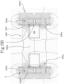
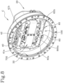
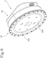
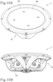
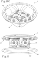
- FIGS 10A, 10B and 10C show a sound diffuser C comprising a housing body 20, a suspension 30a and a radiator 30b; in figures 10B and 10C , a transducer 100 can be seen located inside the housing body 20.
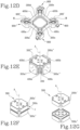
- the coil 200 comprises a first rectilinear portion 200a, a second rectilinear portion 200b, a third rectilinear portion 200c and a fourth rectilinear portion 200d.
- the first 200a, the second 200b, the third 200c and the fourth 200d rectilinear portions are joined together by curved connection sections.
- the first rectilinear portion 200a and the second rectilinear portion 200b are mutually facing and the third rectilinear portion 200c and the fourth rectilinear portion 200d are mutually facing.
- the rectilinear portions all lie on the same plane transverse to the longitudinal axis A and are arranged symmetrically with respect to the longitudinal axis A.
- the rectilinear portions define a square in a plane transverse to the longitudinal axis.
- the outer lateral portion 300b comprises a first part 300b', a second part 300b", a third part 300b" and a fourth part 300b′′′.
- the first 300b', second 300b", third 300b′′′ and fourth 300b"" part are separated from each other and placed laterally to (or to the side of) the first 200a, the second 200b, the third 200c and the fourth 200d rectilinear portion of the coil 200, respectively, so as to define a plurality of air gaps T.
- the transducer 100 comprises a plurality of magnets; in particular, it comprises a first magnet 400a, a second magnet 400b, a third magnet 400c and a fourth magnet 400d.
- the first magnet 400a is placed in a corresponding air gap of the plurality of air gaps T, between the first rectilinear portion 200a and the first part 300b'.
- the second magnet 400b is placed in a corresponding air gap of the plurality of air gaps T, between the second rectilinear portion 200b and the second part 300b".
- the third magnet 400c is placed in a corresponding air gap of the plurality of air gaps T, between the third rectilinear portion 200c and the third part 300b′′′.
- the fourth magnet 400d is placed in a corresponding air gap of the plurality of air gaps T, between the fourth rectilinear portion 200d and the fourth part 300b"".
- the first magnet 400a is movable within the air gap T along a first movement direction M1 parallel to the longitudinal axis A.
- the second magnet 400b is movable within the air gap T along a second movement direction M2 parallel to the longitudinal axis A.
- the third magnet 400a is movable within the air gap T along a third movement direction M3 parallel to the longitudinal axis A.
- the fourth magnet 400d is movable within the air gap T along a fourth movement direction M4 parallel to the longitudinal axis A.
- Each magnet 400a, 400b, 400c, 400d extends along a direction transverse to the longitudinal axis A and parallel to the respective rectilinear portion 200a, 200b, 200c, 200d.
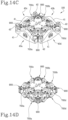
- the magnets are joined together by respective angular elements 900, located in correspondence with the curved connection sections of the coil 200, so as to form a rigid structure movable along the longitudinal direction.
- the rigid structure does not allow movement along a direction transverse to the longitudinal axis A (i.e. along any direction transverse to the longitudinal axis A), while it allows movement along the longitudinal direction.
- Each magnet 400a, 400b, 400c, 400d therefore has a transversal extension with respect to the longitudinal axis A and a longitudinal extension.
- each magnet 400a, 400b, 400c, 400d has two opposite faces, extending along the longitudinal direction between a first end 400a' and a second end 400a".
- each magnet 400a, 400b, 400c, 400d has a south pole "Sa” and a north pole "Na” extending between the first end 400a' and the second end 400a".
- the first magnet 400a and the second magnet 400b have the same pole facing the first rectilinear portion 200a and the second rectilinear portion 200b and the third magnet 400c and the fourth magnet 400d have the same pole facing the third rectilinear portion 200c and the rectilinear portion 200d.
- the sound diffuser C comprises four guide devices, each of which is coupled to an angular element 900 of the plurality of angular elements 900.
- the guide devices allow the movement of each magnet 400a, 400b, 400c, 400d along the respective movement direction M1, M2, M3, M4.
- the guide device comprises an external surface 900', defined by the angular element 900.
- the external surface 900' extends around a guide axis G, parallel to the longitudinal axis A.
- the transducer 100 comprises an upper half-shell 800a and a lower half-shell 800b.
- the guide device comprises an internal surface 800'.
- the internal surface 800' is defined by the upper half-shell 800a.
- the upper half-shell 800a comprises four longitudinal portions, inserted inside the angular elements 900 and defining the internal surfaces 800' for the guide devices. Therefore, the internal surfaces 800' extends around the guide axis G.
- the external surface 900' surrounds the internal surface 800' so as to define a cavity.
- Each guide device comprises an elastic element M, preferably a spring, closed on itself to form a ring arranged in the cavity in contact with the internal surface 800' and the external surface 900', to roll on them moving longitudinally in response to a relative movement between the internal surface 800' and the external surface 900'.
- the upper half-shell 800a is jointly connected to the core of the ferromagnetic circuit 300; therefore, the internal surface 800' is connected, through the upper half-shell 800a, to the core.
- the angular element 900 is jointly connected to a pair of magnets of the plurality of magnets 400a, 400b, 400c and 400d; therefore, the external surface 900' is connected, through the angular element 900, to the pair of magnets to which the angular element 900 is connected.
- the magnets 400a, 400b, 400c and 400d move along the respective movement directions M1, M2, M3, M4
- the external surface 900' moves jointly with the magnets and slides with respect to the internal surface 800' which remains still, and the elastic element rolls between the external surface 900' and the internal surface 800'.
- the outer lateral portion 300b is separated from the core by a plurality of air gaps T extending longitudinally and transversely to the longitudinal direction.
- the inner lateral portion 300c has a high permeability zone near the coil 200, to allow the magnetic field, when the coil 200 is not energized, to close within the inner lateral portion 300c and not within the core.
- the high permeability zone is defined by a slot I transversal to the longitudinal axis A such as to divide the inner lateral portion 300c into an upper sub-portion 300c' and a lower sub-portion 300c" juxtaposed along a direction parallel to the longitudinal axis A and defining respective pole pieces facing the air gap T.
- the core comprises an upper portion and a lower portion.
- the upper portion and the lower portion cooperate to form the central portion 300a of the core, around which the coil 200 is wound, and which extends along the longitudinal axis A.
- the upper portion and the lower portion define a seat for housing the coil 200.
- the core protrudes transversely to the longitudinal axis A and away from the longitudinal axis so as to define an upper protrusion zone, which includes the upper sub-portion 300c' of the inner lateral portion 300c, and a lower protrusion zone, which comprises the bottom sub-portion 300c" of the inner lateral portion 300c.
- the upper sub-portion 300c' and the lower sub-portion 300c" then move towards each other along a direction parallel to the longitudinal axis A for winding at least partially the sides (or walls) of the coil 200 facing towards the air gap T.
- the upper sub- portion 300c' and the lower sub-portion 300c" cooperate to define the slot I, which surrounds the longitudinal axis A.
- the upper sub-portion 300c' and the lower sub-portion 300c" can cooperate to wrap around an entire perimeter of the coil 200 except the point in which the slot I is made.
- the slot I can surround the entire perimeter of the coil 200 except the in the points in correspondence with the curved connection sections.
- the coil 200 is embedded within (or covered by) the ferromagnetic circuit 300 except for the portion close to the slot I which, on the other hand, faces directly the air gap T (i.e. faces directly on the plurality of air gaps).
- the first 200a, the second 200b, the third 200c and the fourth 200d rectilinear portion of the coil 200 are placed laterally to the central portion 300a of the core, i.e. the first 200a, the second 200b, the third 200c and the fourth 200d rectilinear portion of the coil 200 wrap around the central portion 300a of the core.
- the first 200a, second 200b, third 200c and fourth 200d rectilinear portions of the coil 200 are surrounded, below and above with respect to a plane transverse to the longitudinal axis A and passing through a center of the coil 200, by the upper and lower sub-portions 300c', 300c" of the inner lateral portion 300c.
- the core in particular the upper sub-portion 300c' and the lower sub-portion 300c" are interrupted; therefore, the curved connection sections of the coil 200 protrudes with respect to the core outwardly away from the longitudinal axis A.
- the containment shell 800 also comprises a lower half-shell 800b; the upper half-shell 800a and the lower half-shell 800b are mutually juxtaposed along the longitudinal axis "A" and are configured to engage the first 300b', the second 300b", the third 300b′′′ and the fourth part 300b" " of the outer side portion 300b.
- the upper half-shell 800a and the lower half-shell 800b can be configured to engage with the central portion 300c.
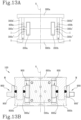
- Figures 14A-14c show, purely by way of example, various embodiments of a mechanical transmission.
- the mechanical transmission can comprise a plurality of actuating members 40 (i.e. a first, a second, a third and a fourth actuating member 40a, 40b.
- a displacement of the magnets along the respective movement direction M1, M2, M3, M4 in one direction corresponds to a displacement of the radiator 30b along the longitudinal axis A in a same direction or in an opposite direction.
- each actuating member 40 of the plurality comprises a single rotary member 41; each individual rotary member 41 is pivoted at a connecting point on a corresponding part of the plurality of parts 300b', 300b", 300b′′′, 300b"" of the outer lateral portion 300b.
- Each actuating member 40 further comprises a connecting body 42 connected to the radiator 30b, so as to transmit the movement to the radiator 30b.
- the acoustic diffuser C comprises a radiator 30b, a suspension 30a and a further radiator 30b' and a further suspension 30a'.
- the actuation member 40 comprises a connecting body 42 connected to the radiator 30b and a further connecting body 42' connected to the further radiator 30b'.
- a guide device comprising a retaining band, preferably made of metal and elastically deformable.
- the retaining band comprises a first section 700a, located in correspondence with the first part 300b' of the outer lateral portion 300b, a second section 700b, located in correspondence with the second portion 300b", a third section 700c, located in correspondence with the third 300b′′′ and a fourth section 700d, placed in correspondence with the fourth portion 300b"".
- Each section 700a, 700b, 700c, 700d comprises a pair of ends; each end is connected to an angular element 900. In this way, the retaining band perimetrically surrounds the outer lateral portion 300b.
- the guide device comprises a plurality of connection elements, to connect a central area of a section 700a, 700b, 700c, 700d of the retaining band to a respective part of the outer lateral portion 300b.
- connection elements to connect a central area of a section 700a, 700b, 700c, 700d of the retaining band to a respective part of the outer lateral portion 300b.
- the angular elements move and the retaining band flexes.
- the ends of the sections move together with the angular elements 900, while the central area remains stationary.
- the invention achieves the preset aims eliminating the drawbacks of the prior art.
- the invention provides a transducer and a sound diffuser having a small overall size in the movement direction of the at least one magnet.
- the invention provides a transducer with high electro-mechanical efficiency and robustness.
- the invention provides a transducer which is easy to assemble.
- the invention provides a balanced sound diffuser at inertial level even when it operates at low frequencies.
- the invention provides a sound diffuser with compact dimensions but with a high SPL value.
Landscapes
- Engineering & Computer Science (AREA)
- Physics & Mathematics (AREA)
- Acoustics & Sound (AREA)
- Signal Processing (AREA)
- Manufacturing & Machinery (AREA)
- Multimedia (AREA)
- Electromagnetism (AREA)
- Audible-Bandwidth Dynamoelectric Transducers Other Than Pickups (AREA)
- Obtaining Desirable Characteristics In Audible-Bandwidth Transducers (AREA)
- Electrostatic, Electromagnetic, Magneto- Strictive, And Variable-Resistance Transducers (AREA)
Claims (12)
- Schalldiffusor (C), umfassend:- ein Gehäuse (20);- einen Wandler (100), der sich im Gehäuse (20) befindet und Folgendes einschließt:eine Spule (200), einschließend eine Vielzahl von Windungen (201), die jeweils in einer jeweiligen Ebene (γ) quer zur Längsachse (A) liegen, wobei die Windungen (201) entlang der Längsachse (A) nebeneinander platziert sind und die Längsachse (A) umgeben, die Spule (200) eine Vielzahl von geradlinigen Abschnitten quer zur Längsachse (A) einschließt und die Vielzahl von geradlinigen Abschnitten einen ersten, einen zweiten, einen dritten und einen vierten geradlinigen Abschnitt (200a, 200b, 200c, 200d) einschließt, die durch jeweilige gekrümmte Verbindungssektionen zusammengefügt sind, wobei der erste und der zweite geradlinige Abschnitt (200a, 200b) einander zugewandt sind und der dritte und der vierte geradlinige Abschnitt (200c, 200d) einander zugewandt sind;einen ferromagnetischen Kreislauf (300), einschließend einen Kern, versehen mit einem mittigen Abschnitt (300a), der rund um die Spule (200) gewunden ist, und einen äußeren seitlichen Abschnitt (300b), der an der Seite der Spule (200) befindlich ist und zumindest die Spule (200) teilweise umgibt, wobei der äußere seitliche Abschnitt (300b) vom Kern durch einen Luftspalt (T), der sich längs erstreckt, getrennt angeordnet ist, der äußere seitliche Abschnitt (300b) eine Vielzahl von Teilen umfasst, die die Spule (200) umgeben und mit der entsprechenden Vielzahl von geradlinigen Abschnitten der Spule kooperieren, um eine Vielzahl von Luftspalten (T) zu definieren, wobei die Vielzahl von Teilen des äußeren seitlichen Abschnitts (300b) einen ersten, einen zweiten, einen dritten und einen vierten Teil (300b', 300b", 300b"', 300b"") einschließt;eine Vielzahl von Magneten (400a, 400b, 400c, 400d), wobei ein jeder Magnet der Vielzahl von Magneten in einem jeweiligen Luftspalt (T) der Vielzahl von Luftspalten befindlich ist, die Vielzahl von Magneten einen ersten Magnet (400a), der zwischen dem ersten geradlinigen Abschnitt (200a) und dem ersten Teil (300b') platziert ist, einen zweiten Magnet (400b), der zwischen dem zweiten geradlinigen Abschnitt (200b) und dem zweiten Teil (300b") platziert ist, einen dritten Magnet (400c), der zwischen dem dritten geradlinigen Abschnitt (200c) und dem dritten Teil (300b"') platziert ist, und einen vierten Magnet (400d), der zwischen dem vierten geradlinigen Abschnitt (200d) und dem vierten Teil (300b"") platziert ist, umfasst, wobei der erste (400a), der zweite (400b), der dritte (400c) und der vierte Magnet (400d) entlang jeweiliger Bewegungsrichtungen (M1, M2, M3, M4) parallel zur Längsachse (A) bewegbar sind und die Spule (200) unter Strom gesetzt werden kann, um ein stromerzeugendes Magnetfeld zu erzeugen, das bewirkt, dass sich die Vielzahl von Magneten (400a, 400b, 400c, 400d) entlang der jeweiligen Bewegungsrichtungen (M1, M2, M3, M4) bewegt;- einen Radiator (30b);- eine Federung (30a), die ausgelegt ist, um dem Radiator (30b) zu erlauben, relativ zum Gehäuse (20) zu schwingen, wobei der Radiator (30b) betriebswirksam mit der Vielzahl von Magneten (400a, 400b, 400c, 400d) gekuppelt ist, sodass eine Bewegung der Vielzahl von Magneten (400a, 400b, 400c, 400d) entlang der jeweiligen Bewegungsrichtungen (M1, M2, M3, M4) parallel zur Längsachse (A) einer Schwingung des Radiators (30b) entlang der Längsachse (A) entspricht.
- Schalldiffusor (C) nach Anspruch 1, wobei ein jeder Magnet der Vielzahl sich entlang einer Richtung quer zur Längsachse (A) und parallel zum jeweiligen geradlinigen Abschnitt (200a, 200b, 200c, 200d) erstreckt und die Magnete der Vielzahl von Magneten durch jeweilige Winkelelemente zusammengefügt sind, die sich an den gekrümmten Verbindungssektionen der Spule (200) befinden, um eine steife Struktur zu bilden, die entlang der Längsrichtung bewegbar ist.
- Schalldiffusor (C) nach Anspruch 2, umfassend vier Führungsvorrichtungen, von denen eine jede mit einem Winkelelement gekuppelt ist, um die Bewegung eines jeden Magnets der Vielzahl von Magneten entlang der jeweiligen Bewegungsrichtung (M1, M2, M3, M4) zu erlauben.
- Schalldiffusor (C) nach Anspruch 3, wobei eine jede Führungsvorrichtung Folgendes umfasst:- eine interne Oberfläche, die sich rund um eine längs ausgerichtete Führungsachse erstreckt, wobei die interne Oberfläche mit dem Kern verbunden ist;- eine externe Oberfläche, die sich rund um die Führungsachse erstreckt und die interne Oberfläche umgibt, um einen Hohlraum zu definieren, und die mit einem Paar von Magneten der Vielzahl von Magneten verbunden ist;- ein elastisches Element (M), das um sich selbst geschlossen ist, um einen Ring zu bilden, angeordnet im Hohlraum in Kontakt mit der internen Oberfläche und der externen Oberfläche, um auf diesen zu rollen und sich längs als Reaktion auf eine relative Bewegung zwischen der internen Oberfläche und der externen Oberfläche zu bewegen.
- Schalldiffusor (C) nach einem der vorhergehenden Ansprüche, wobei ein jeder Magnet der Vielzahl ein erstes Ende (400a') und ein zweites Ende (400a") aufweist, die der Längsrichtung entgegengesetzt sind, und einen Südpol (Sa, Sb, Sc, Sd) und einen Nordpol (Na, Nb, Ne, Nd), wobei sich sowohl der Nord- als auch der Südpol zwischen dem ersten Ende (400a') und dem zweiten Ende (400a") parallel zur Längsachse (A) erstrecken, wobei beim ersten und zweiten Magnet (400a, 400b) der gleiche Pol (Sa, Na, Sb, Nb) der Spule (200) zugewandt ist und beim dritten und vierten Magnet (400c, 400d) der gleiche Pol (Sc, Ne, Sd, Nd) der Spule (200) zugewandt ist.
- Schalldiffusor (C) nach einem der vorhergehenden Ansprüche, wobei der ferromagnetische Kreislauf (300) einen inneren seitlichen Abschnitt (300c) umfasst, der an der Seite der Spule (200) befindlich und zwischen der Spule (200) und der Vielzahl von Magneten (400a) eingesetzt ist und der innere seitliche Abschnitt (300c) eine Zone mit hoher magnetischer Durchlässigkeit in der Nähe der Spule (200) aufweist.
- Schalldiffusor (C) nach Anspruch 6, wobei die Zone durch eine Nut (I) quer zur Längsachse (A) definiert ist, sodass der innere seitliche Abschnitt (300c) in einen oberen Unterabschnitt (300c') und einen unteren Unterabschnitt (300c") geteilt ist, die entlang einer Richtung parallel zur Längsachse (A) nebeneinander platziert sind und jeweilige Polerweiterungen definieren, die hinführend zum Luftspalt (T) gerichtet sind.
- Schalldiffusor (C) nach Anspruch 7, wobei der obere Unterabschnitt (300c') und der untere Unterabschnitt (300c") des inneren seitlichen Abschnitts (300c) in einem Stück mit dem Kern ausgebildet sind und aus dem mittigen Abschnitt (300a) hinführend zum äußeren seitlichen Abschnitt (300b) herausragen.
- Schalldiffusor (C) nach Anspruch 7 oder 8, wobei sich der Kern entlang der Längsachse (A) erstreckt, um einen mittigen Abschnitt (300a) zu definieren und quer in Bezug auf die Längsachse (A) und wegführend von der Längsachse (A) hervorspringt, um eine obere Vorsprungszone zu definieren, umfassend den unteren Unterabschnitt (300c'), und eine untere Vorsprungszone, umfassend den unteren Unterabschnitt (300c"), wobei die obere Vorsprungszone und die untere Vorsprungszone unterseitig und oberseitig die Spule auf symmetrische Weise in Bezug auf eine Ebene quer zur Längsachse (A) umgeben und durch eine Mitte der Spule (200) führen.
- Schalldiffusor (C) nach einem der vorhergehenden Abschnitte, umfassend einen mechanischen Antrieb, einschließend mindestens ein Betätigungselement (40), das zwischen dem mindestens einen Magnet (400a) und dem Radiator (30b) eingesetzt ist, um den Radiator (30b) in die dem mindestens einen Magnet (400a) entgegengesetzte Richtung zu bewegen.
- Schalldiffusor (C) nach einem der vorhergehenden Abschnitte, wobei der Kern aus einem gesinterten Magnetverbundstoff, SMC, ausgebildet ist.
- Verfahren zur Herstellung eines Schalldiffusors (C) nach einem der vorhergehenden Ansprüche, wobei das Verfahren die folgenden Schritte umfasst:- Bereitstellen des Wandlers (100), umfassend:die Spule (200), umfassend eine Vielzahl von Windungen (201), die sich jeweils in eine jeweilige Ebene (γ) quer zur Längsachse (A) liegen, wobei die Windungen (201) entlang der Längsachse (A) nebeneinander platziert sind und die Längsachse (A) umgeben, die Spule (200) eine Vielzahl von geradlinigen Abschnitten quer zur Längsachse (A) einschließt, aufweisend einen ersten, einen zweiten, einen dritten und einen vierten geradlinigen Abschnitt (200a, 200b, 200c, 200d), die durch jeweilige gekrümmte Verbindungssektionen zusammengefügt sind, wobei der erste und der zweite geradlinige Abschnitt (200a, 200b) einander zugewandt sind und der dritte und der vierte geradlinige Abschnitt (200c, 200d) einander zugewandt sind;wobei der ferromagnetische Kreislauf (300) Folgendes umfasst:den Kern, der mit einem mittigen Abschnitt (300a) versehen ist, rund um den die Spule (200) gewunden ist;den äußeren seitlichen Abschnitt (300b), der an der Seite der Spule (200) befindlich ist und von der Spule (200) durch einen Luftspalt (T) getrennt angeordnet ist und eine Vielzahl von Teilen umfasst, die die Spule (200) umgeben und mit der entsprechenden Vielzahl von geradlinigen Abschnitten kooperieren, um eine Vielzahl von Luftspalten (T) zu definieren, und die einen ersten, einen zweiten, einen dritten und einen vierten Teil (300b', 300b", 300b"', 300b"") einschließen;vier magnetisierbare Elemente;- Positionieren der magnetisierbaren Elemente in den jeweiligen Luftspalt der Vielzahl von Luftspalten (T);- Bereitstellen eines magnetisierenden Hilfskreislaufs (10) auf der Außenseite des Wandlers (100), der ausgelegt ist, um die magnetisierbaren Elemente zu magnetisieren;- Magnetisieren der magnetisierbaren Elemente, die im jeweiligen Luftspalt (T) befindlich sind, durch Aktivieren des magnetisierenden Hilfskreislaufs (10), um eine Vielzahl von Permanentmagneten (400a, 400b, 400c, 400d) herzustellen, wobei ein jeder Magnet der Vielzahl in einem jeweiligen Luftspalt der Vielzahl von Luftspalten (T) platziert ist und die Vielzahl von Magneten einen ersten, einen zweiten, einen dritten und einen vierten Magnet (400a, 400b, 400c, 400d) umfasst, die entlang einer jeweiligen Bewegungsrichtung (M1, M2, M3, M4) parallel zur Längsachse bewegbar sind.
Priority Applications (1)
| Application Number | Priority Date | Filing Date | Title |
|---|---|---|---|
| EP25153194.3A EP4539503A3 (de) | 2021-12-29 | 2022-12-27 | Schalldiffusor und verfahren zur diffusion eines schalls durch einen schalldiffusor |
Applications Claiming Priority (2)
| Application Number | Priority Date | Filing Date | Title |
|---|---|---|---|
| IT102021000032906A IT202100032906A1 (it) | 2021-12-29 | 2021-12-29 | Diffusore acustico e metodo per estendere la risposta alle basse frequenze di un diffusore acustico. |
| IT102021000032897A IT202100032897A1 (it) | 2021-12-29 | 2021-12-29 | Trasduttore per un diffusore acustico e metodo per la produzione del trasduttore. |
Related Child Applications (2)
| Application Number | Title | Priority Date | Filing Date |
|---|---|---|---|
| EP25153194.3A Division EP4539503A3 (de) | 2021-12-29 | 2022-12-27 | Schalldiffusor und verfahren zur diffusion eines schalls durch einen schalldiffusor |
| EP25153194.3A Division-Into EP4539503A3 (de) | 2021-12-29 | 2022-12-27 | Schalldiffusor und verfahren zur diffusion eines schalls durch einen schalldiffusor |
Publications (3)
| Publication Number | Publication Date |
|---|---|
| EP4207809A1 EP4207809A1 (de) | 2023-07-05 |
| EP4207809B1 true EP4207809B1 (de) | 2025-02-26 |
| EP4207809C0 EP4207809C0 (de) | 2025-02-26 |
Family
ID=84602605
Family Applications (2)
| Application Number | Title | Priority Date | Filing Date |
|---|---|---|---|
| EP22216753.8A Active EP4207809B1 (de) | 2021-12-29 | 2022-12-27 | Schalldiffusor und verfahren zur herstellung eines schalldiffusors |
| EP25153194.3A Pending EP4539503A3 (de) | 2021-12-29 | 2022-12-27 | Schalldiffusor und verfahren zur diffusion eines schalls durch einen schalldiffusor |
Family Applications After (1)
| Application Number | Title | Priority Date | Filing Date |
|---|---|---|---|
| EP25153194.3A Pending EP4539503A3 (de) | 2021-12-29 | 2022-12-27 | Schalldiffusor und verfahren zur diffusion eines schalls durch einen schalldiffusor |
Country Status (4)
| Country | Link |
|---|---|
| US (2) | US12309566B2 (de) |
| EP (2) | EP4207809B1 (de) |
| JP (1) | JP2023098870A (de) |
| CN (1) | CN116367064A (de) |
Families Citing this family (1)
| Publication number | Priority date | Publication date | Assignee | Title |
|---|---|---|---|---|
| EP4550839A1 (de) | 2023-11-03 | 2025-05-07 | Powersoft SpA | Lautsprecher mit rollaufhängungsvorrichtung |
Family Cites Families (16)
| Publication number | Priority date | Publication date | Assignee | Title |
|---|---|---|---|---|
| NL104049C (de) * | 1954-10-28 | |||
| JPS5723994Y2 (de) * | 1976-12-03 | 1982-05-24 | ||
| JPS6022346B2 (ja) | 1976-12-23 | 1985-06-01 | 富士通株式会社 | フオトマスクのパタ−ン修正方法 |
| US5216723A (en) | 1991-03-11 | 1993-06-01 | Bose Corporation | Permanent magnet transducing |
| US5546469A (en) * | 1994-08-15 | 1996-08-13 | Donahoe; Danny T. | Sound transducer |
| US5802193A (en) * | 1997-04-08 | 1998-09-01 | Kieltyka; William J. | Outdoor loudspeaker system |
| GB0122732D0 (en) | 2001-09-20 | 2001-11-14 | Isis Innovations Ltd | Electromechanical transducer linear compressor and radio transmission antenna |
| US8295536B2 (en) * | 2010-03-31 | 2012-10-23 | Bose Corporation | Moving magnet levered loudspeaker |
| US8565461B2 (en) | 2011-03-16 | 2013-10-22 | Cochlear Limited | Bone conduction device including a balanced electromagnetic actuator having radial and axial air gaps |
| US10028062B2 (en) * | 2013-03-15 | 2018-07-17 | Bose Corporation | Driving plural armatures with a common stator |
| US9601969B2 (en) | 2014-03-07 | 2017-03-21 | Bose Corporation | Inhibiting rocking of loads driven by plural levers |
| US9357279B2 (en) | 2014-03-07 | 2016-05-31 | Bose Corporation | Elastomeric torsion bushings for levered loudspeakers |
| WO2016020835A1 (en) * | 2014-08-04 | 2016-02-11 | Katz David Micah | Electromechanical transducer with non-circular voice coil |
| EP3777238A1 (de) * | 2018-04-11 | 2021-02-17 | Dali A/S | Lautsprechereinheit mit doppelter schwingspule |
| IT202100001487A1 (it) | 2021-01-26 | 2022-07-26 | Powersoft S P A | Dispositivo acustico |
| IT202200026061A1 (it) | 2022-12-20 | 2024-06-20 | Powersoft S P A | Altoparlante e metodo per diffondere un suono. |
-
2022
- 2022-12-27 EP EP22216753.8A patent/EP4207809B1/de active Active
- 2022-12-27 EP EP25153194.3A patent/EP4539503A3/de active Pending
- 2022-12-28 US US18/147,211 patent/US12309566B2/en active Active
- 2022-12-28 JP JP2022212207A patent/JP2023098870A/ja active Pending
- 2022-12-29 CN CN202211743385.1A patent/CN116367064A/zh active Pending
-
2025
- 2025-04-22 US US19/186,386 patent/US20250254467A1/en active Pending
Also Published As
| Publication number | Publication date |
|---|---|
| JP2023098870A (ja) | 2023-07-11 |
| CN116367064A (zh) | 2023-06-30 |
| EP4539503A2 (de) | 2025-04-16 |
| EP4207809A1 (de) | 2023-07-05 |
| EP4207809C0 (de) | 2025-02-26 |
| EP4539503A3 (de) | 2025-07-23 |
| US20250254467A1 (en) | 2025-08-07 |
| US12309566B2 (en) | 2025-05-20 |
| US20230209273A1 (en) | 2023-06-29 |
Similar Documents
| Publication | Publication Date | Title |
|---|---|---|
| EP0574574B1 (de) | Betätiger für aktive vibrationssteuerung | |
| EP1101273B1 (de) | Tieffrequenzschwinger | |
| CA2493603C (en) | Actuator capable of moving in axial and rotational directions | |
| JP5248598B2 (ja) | 機械的振動エネルギーを電気エネルギーに変換するための永久磁石による発電機 | |
| JP7234256B2 (ja) | 機械的振動エネルギーを電気エネルギーに変換するための電気機械発電機 | |
| US5444313A (en) | Electromagnetic actuator having two opposite phase movable parts | |
| KR20110120242A (ko) | 진동 발생 장치 | |
| JP2002525007A5 (de) | ||
| US20250254467A1 (en) | Sound diffuser and a method for diffusing a sound through a sound diffuser | |
| JP7362644B2 (ja) | 機械的振動エネルギーを電気エネルギーに変換するための電気機械発電機 | |
| JP4039359B2 (ja) | アクチュエータ | |
| WO2007001042A1 (ja) | 振動アクチュエータ | |
| CN107431425B (zh) | 线性振动马达 | |
| WO2012008417A1 (ja) | 可動鉄心型リニアアクチュエータ | |
| CN114337181B (zh) | 一种双频振动激励器 | |
| JP2020121240A (ja) | 振動モータ | |
| JP3404139B2 (ja) | 電磁アクチュエータ | |
| WO2020027157A1 (ja) | リニア振動アクチュエータ | |
| JPH0528464U (ja) | 振動アクチユエータ | |
| IT202100032897A1 (it) | Trasduttore per un diffusore acustico e metodo per la produzione del trasduttore. | |
| JP2012165554A (ja) | リニアアクチュエータ |
Legal Events
| Date | Code | Title | Description |
|---|---|---|---|
| PUAI | Public reference made under article 153(3) epc to a published international application that has entered the european phase |
Free format text: ORIGINAL CODE: 0009012 |
|
| STAA | Information on the status of an ep patent application or granted ep patent |
Free format text: STATUS: THE APPLICATION HAS BEEN PUBLISHED |
|
| AK | Designated contracting states |
Kind code of ref document: A1 Designated state(s): AL AT BE BG CH CY CZ DE DK EE ES FI FR GB GR HR HU IE IS IT LI LT LU LV MC ME MK MT NL NO PL PT RO RS SE SI SK SM TR |
|
| STAA | Information on the status of an ep patent application or granted ep patent |
Free format text: STATUS: REQUEST FOR EXAMINATION WAS MADE |
|
| 17P | Request for examination filed |
Effective date: 20231222 |
|
| RBV | Designated contracting states (corrected) |
Designated state(s): AL AT BE BG CH CY CZ DE DK EE ES FI FR GB GR HR HU IE IS IT LI LT LU LV MC ME MK MT NL NO PL PT RO RS SE SI SK SM TR |
|
| RIC1 | Information provided on ipc code assigned before grant |
Ipc: H04R 9/02 20060101ALN20240610BHEP Ipc: H04R 11/02 20060101AFI20240610BHEP |
|
| RIC1 | Information provided on ipc code assigned before grant |
Ipc: H04R 9/02 20060101ALN20240725BHEP Ipc: H04R 11/02 20060101AFI20240725BHEP |
|
| GRAP | Despatch of communication of intention to grant a patent |
Free format text: ORIGINAL CODE: EPIDOSNIGR1 |
|
| STAA | Information on the status of an ep patent application or granted ep patent |
Free format text: STATUS: GRANT OF PATENT IS INTENDED |
|
| RIC1 | Information provided on ipc code assigned before grant |
Ipc: H04R 9/02 20060101ALN20240829BHEP Ipc: H04R 11/02 20060101AFI20240829BHEP |
|
| INTG | Intention to grant announced |
Effective date: 20240923 |
|
| GRAS | Grant fee paid |
Free format text: ORIGINAL CODE: EPIDOSNIGR3 |
|
| GRAA | (expected) grant |
Free format text: ORIGINAL CODE: 0009210 |
|
| STAA | Information on the status of an ep patent application or granted ep patent |
Free format text: STATUS: THE PATENT HAS BEEN GRANTED |
|
| AK | Designated contracting states |
Kind code of ref document: B1 Designated state(s): AL AT BE BG CH CY CZ DE DK EE ES FI FR GB GR HR HU IE IS IT LI LT LU LV MC ME MK MT NL NO PL PT RO RS SE SI SK SM TR |
|
| REG | Reference to a national code |
Ref country code: GB Ref legal event code: FG4D |
|
| REG | Reference to a national code |
Ref country code: CH Ref legal event code: EP |
|
| REG | Reference to a national code |
Ref country code: DE Ref legal event code: R096 Ref document number: 602022011076 Country of ref document: DE |
|
| REG | Reference to a national code |
Ref country code: IE Ref legal event code: FG4D |
|
| U01 | Request for unitary effect filed |
Effective date: 20250321 |
|
| U07 | Unitary effect registered |
Designated state(s): AT BE BG DE DK EE FI FR IT LT LU LV MT NL PT RO SE SI Effective date: 20250327 |
|
| PG25 | Lapsed in a contracting state [announced via postgrant information from national office to epo] |
Ref country code: RS Free format text: LAPSE BECAUSE OF FAILURE TO SUBMIT A TRANSLATION OF THE DESCRIPTION OR TO PAY THE FEE WITHIN THE PRESCRIBED TIME-LIMIT Effective date: 20250526 |
|
| PG25 | Lapsed in a contracting state [announced via postgrant information from national office to epo] |
Ref country code: PL Free format text: LAPSE BECAUSE OF FAILURE TO SUBMIT A TRANSLATION OF THE DESCRIPTION OR TO PAY THE FEE WITHIN THE PRESCRIBED TIME-LIMIT Effective date: 20250226 |
|
| PG25 | Lapsed in a contracting state [announced via postgrant information from national office to epo] |
Ref country code: ES Free format text: LAPSE BECAUSE OF FAILURE TO SUBMIT A TRANSLATION OF THE DESCRIPTION OR TO PAY THE FEE WITHIN THE PRESCRIBED TIME-LIMIT Effective date: 20250226 |
|
| PG25 | Lapsed in a contracting state [announced via postgrant information from national office to epo] |
Ref country code: NO Free format text: LAPSE BECAUSE OF FAILURE TO SUBMIT A TRANSLATION OF THE DESCRIPTION OR TO PAY THE FEE WITHIN THE PRESCRIBED TIME-LIMIT Effective date: 20250526 Ref country code: IS Free format text: LAPSE BECAUSE OF FAILURE TO SUBMIT A TRANSLATION OF THE DESCRIPTION OR TO PAY THE FEE WITHIN THE PRESCRIBED TIME-LIMIT Effective date: 20250626 |
|
| PG25 | Lapsed in a contracting state [announced via postgrant information from national office to epo] |
Ref country code: HR Free format text: LAPSE BECAUSE OF FAILURE TO SUBMIT A TRANSLATION OF THE DESCRIPTION OR TO PAY THE FEE WITHIN THE PRESCRIBED TIME-LIMIT Effective date: 20250226 |
|
| PG25 | Lapsed in a contracting state [announced via postgrant information from national office to epo] |
Ref country code: GR Free format text: LAPSE BECAUSE OF FAILURE TO SUBMIT A TRANSLATION OF THE DESCRIPTION OR TO PAY THE FEE WITHIN THE PRESCRIBED TIME-LIMIT Effective date: 20250527 |
|
| PG25 | Lapsed in a contracting state [announced via postgrant information from national office to epo] |
Ref country code: SM Free format text: LAPSE BECAUSE OF FAILURE TO SUBMIT A TRANSLATION OF THE DESCRIPTION OR TO PAY THE FEE WITHIN THE PRESCRIBED TIME-LIMIT Effective date: 20250226 |
|
| PG25 | Lapsed in a contracting state [announced via postgrant information from national office to epo] |
Ref country code: CZ Free format text: LAPSE BECAUSE OF FAILURE TO SUBMIT A TRANSLATION OF THE DESCRIPTION OR TO PAY THE FEE WITHIN THE PRESCRIBED TIME-LIMIT Effective date: 20250226 |
|
| PG25 | Lapsed in a contracting state [announced via postgrant information from national office to epo] |
Ref country code: SK Free format text: LAPSE BECAUSE OF FAILURE TO SUBMIT A TRANSLATION OF THE DESCRIPTION OR TO PAY THE FEE WITHIN THE PRESCRIBED TIME-LIMIT Effective date: 20250226 |